


Chapter 17.86
IMPORT, EXPORT, EXCAVATIONS AND FILLS
Sections:
17.86.010 Import and Export of Earth Materials.
17.86.040 Ridgeline Preservation and Hillside Development.
17.86.060 Slopes Subject to Hillside Development.
17.86.010 Import and Export of Earth Materials.
Grading shall be balanced on site whenever possible. Import and export of earth materials shall be subject to all of the following:
A. The point or points of access to the public street or streets for export or import shall be shown on the grading plan and shall be located as approved by the City Engineer;
B. The haul route for export or import shall be approved by the City Engineer prior to commencement of any export or import of material to or from the site;
C. The last fifty (50) feet of the outhaul road immediately adjoining the street if downgrade to the street has a grade no steeper than three percent (3%);
D. An unobstructed sight distance of not less than three hundred (300) feet in each direction up and down the public street; and
E. Security for import or export may be required by the City Engineer. (Ord. 13-8 § 4 (Exh. A), 6/11/13)
17.86.020 Excavations.
A. Maximum Cut Slope. Cuts shall not be steeper in slope than two (2) horizontal to one (1) vertical. The City Engineer may allow a slope greater than two to one (2:1) for special circumstances or site conditions. In this case the owner must furnish a geotechnical engineering or an engineering geology report, or both, conforming with the requirements of the City Building Code, stating that the site has been investigated and giving an opinion that a cut at a steeper slope will be stable and not create a hazard to public or private property. Substantiating calculations and supporting data may be required where the City Engineer determines that such information is necessary to verify the stability and safety of the proposed slope.
B. Slope Surface Protection. All slopes must be stabilized against surface erosion. Stabilization may be accomplished through the application of erosion control blankets, soil stabilizers or other means as approved by the City Engineer.
C. Drainage. Drainage, including drainage terraces and overflow protection, shall be provided as required by Chapter 17.87 (Drainage and Terracing). (Ord. 13-8 § 4 (Exh. A), 6/11/13)
17.86.030 Fills.
A. General. Unless otherwise recommended in the geotechnical report, fills shall conform to provisions of this section.
B. Preparation of Ground. Fill slopes shall not be constructed on natural slopes steeper than two (2) units horizontal to one (1) unit vertical (fifty percent (50%) slope). The ground surface shall be prepared to receive fill by removing vegetation, topsoil, and other unsuitable materials (including any existing fill that does not meet the requirements of this code), and scarifying the ground to provide a bond with the fill material.
Subdrains shall be provided under all fills placed in natural drainage courses and in other locations where seepage is evident except where the geotechnical engineer or engineering geologist recommends otherwise. Such subdrainage systems shall be of a material and design approved by the geotechnical engineer and acceptable to the City Engineer. The geotechnical engineer shall provide continuous inspection during the process of subdrain installation. The location of the subdrains shall be shown on a plan prepared by the geotechnical engineer. Excavations for the subdrains shall be inspected by the engineering geologist when such subdrains are included in the recommendations of the engineering geology report.
C. Benching. Where existing grade is at a slope steeper than five (5) units horizontal to one (1) unit vertical (twenty percent (20%) slope) and the depth of the fill exceeds five (5) feet, benching shall be provided into sound bedrock or other competent material as determined by the geotechnical engineer. The ground preparation shall be in accordance with Figure 17.86-1 (Benching Details) or as determined by the geotechnical engineer. When fill is placed over a cut, a key shall be provided which is at least ten (10) feet in width and two (2) feet in depth. The area beyond the toe of the fill shall be sloped for sheet overflow or a paved drain shall be constructed thereon. The geotechnical engineer or engineering geologist, or both, shall inspect and approve the key as being suitable for the foundation and placement of fill material before any fill material is placed on the excavation.
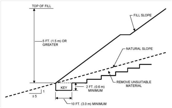
Figure 17.86-1
Benching Details
D. Fill Material. Fill shall not include organic, frozen, or other deleterious materials. Except as permitted by the City Engineer, no rock or similar irreducible materials with a maximum dimension greater than twelve (12) inches in any dimension shall be included in fills.
Exception: The City Engineer may permit the placement of larger rock when the geotechnical engineer properly devises and recommends a method of placement and continuously inspects its placement and approves the fill stability. All of the following shall also apply:
1. Prior to issuance of the grading permit, potential rock disposal areas shall be delineated on the grading plan;
2. Rock sizes greater than twelve (12) inches in maximum dimension shall be ten (10) feet or more below grade, as measured vertically;
3. Rocks shall be placed so as to assure the filling of voids with well-graded soil;
4. The reports submitted by the geotechnical engineer shall acknowledge the placement of the oversized material and whether the work was performed in accordance with the City Engineer’s recommendations and the approved plans; and
5. The locations of oversized rock dispersal areas shall be shown on the as built plan.
E. Compaction. All fill shall be compacted to a minimum compaction of ninety percent (90%) of maximum dry density as determined by ASTM D1557, Modified Proctor, in lifts not exceeding twelve (12) inches in depth, within forty (40) feet below finished grade and ninety-three percent (93%) of maximum dry density, deeper than forty (40) feet below finished grade, unless a lower relative compaction (not less than ninety percent (90%) of maximum dry density) is justified by the geotechnical engineer and approved by the City Engineer. Where ASTM D1557, Modified Proctor, is not applicable, a test acceptable to the City Engineer shall be used.
Fills used to elevate structures in compliance with Chapter 10.06 (Floodplain Management) shall be compacted to ninety-five percent (95%) of maximum dry density.
Field density shall be determined by a method acceptable to the City Engineer. However, not less than ten percent (10%) of the required density tests shall be obtained by the Sand Cone Method (ASTM D1556). The required ten percent (10%) by the Sand Cone Method shall be uniformly distributed throughout the depths and limits of the fill.
Fill slopes steeper than, or equal to, two (2) units horizontal to one (1) unit vertical (fifty percent (50%) slope) shall be constructed by the placement of soil a sufficient distance beyond the proposed finish slope to allow compaction equipment to operate at the outer surface limits of the final slope surface. The excess fill is to be removed prior to completion or rough grading. Other construction procedures may be utilized when it is first shown to the satisfaction of the City Engineer that the angle of slope, construction method and other factors will accomplish the intent of this section.
F. Maximum Fill Slope. The slope of fill surfaces shall be no steeper than is safe for the intended use. The City Engineer may allow a slope of steeper than two (2) units horizontal to one (1) unit vertical (fifty percent (50%) slope) for special circumstances or site conditions. The steepness of fill slopes shall be determined by a geotechnical engineering report conforming with the requirements of the City Building Code and containing a statement by the geotechnical engineer that the site has been investigated, with an opinion that a steeper fill slope will be stable and will not create a hazard to public or private property. Substantiating calculations and supporting data may be required where the City Engineer determines that such information is necessary to verify the stability and safety of the proposed slope. The City Engineer may require the fill slope to be constructed with a face flatter than two (2) units horizontal to one (1) unit vertical (fifty percent (50%) slope) if the City Engineer finds it necessary for stability and safety of the slope.
G. Slopes to Receive Fill. Where fill is to be placed above the top of an existing slope steeper than three (3) units horizontal to one (1) unit vertical (thirty-three percent (33%) slope), the toe of the fill shall be set back from the top edge of the existing slope a minimum distance of six (6) feet measured horizontally or such other distance as may be specifically recommended by a geotechnical engineer or engineering geologist and is approved by the City Engineer.
H. Inspection of Fill. For engineered grading, the geotechnical engineer shall provide sufficient inspections during the preparation of the natural ground and the placement and compaction of the fill to ensure that the work is being performed in accordance with the conditions of plan approval and the appropriate requirements of this chapter. In addition to the above, the geotechnical engineer shall provide continuous inspection during the entire fill placement and compaction of fills that will exceed a vertical height or depth of thirty (30) feet or result in a slope surface steeper than two (2) units horizontal to one (1) unit vertical (fifty percent (50%) slope).
I. Testing of Fills. Sufficient tests of the fill soils shall be made to determine the density thereof and to verify compliance of the soil properties with the design requirements, including soil types and shear strengths in accordance with the standards established by the City Engineer. The results of such testing shall be included in the report required by this chapter.
J. Drainage. Drainage, including drainage terraces and overflow protection, shall be provided as required by Chapter 17.87 (Drainage and Terracing). (Ord. 13-8 § 4 (Exh. A), 6/11/13)
17.86.040 Ridgeline Preservation and Hillside Development.
Grading where average slopes are greater than ten percent (10%) and involving more than one hundred (100) cubic yards is subject to Section 17.51.020 (Hillside Development). For specific requirements involving view corridors, scenic vistas, ridgelines, grading on slopes exceeding fifty percent (50%), and maximum slope heights, refer to Section 17.38.070 (RP—Ridgeline Preservation Overlay Zone) and Section 17.51.020 (Hillside Development). (Ord. 13-8 § 4 (Exh. A), 6/11/13)
17.86.050 Slope Setbacks.
A. General. Cut and fill slopes shall be set back from property lines in accordance with this section. Setback dimensions shall be horizontal distances measured perpendicular to the property line and shall be as shown in Figure 17.86-2 (Setback Dimensions), unless substantiating data is submitted justifying reduced setbacks and reduced setbacks are recommended in a geotechnical engineering and engineering geology report that has been approved by the City Engineer.
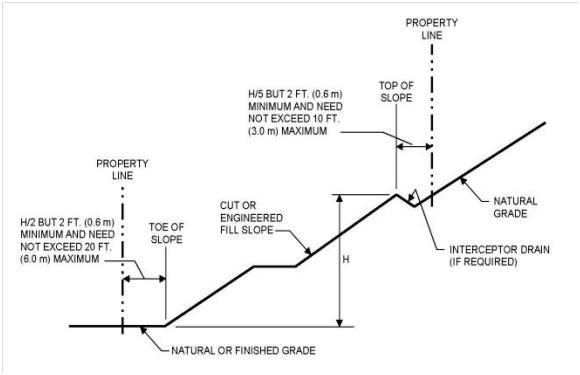
Figure 17.86-2
Setback Dimensions
B. Top of Cut Slope. The setback at the top of a cut slope shall not be less than that shown in Figure 17.86-2 (Setback Dimensions), or less than is required to accommodate any required interceptor drains, whichever is greater. For graded slopes, the property line between adjacent lots shall be at the apex of the berm at the top of the slope. Property lines between adjacent lots shall not be located on a graded slope steeper than five (5) units horizontal to one (1) unit vertical (twenty percent (20%) slope).
C. Toe of Fill Slope. The setback from the toe of a fill slope shall not be less than that shown by Figure 17.86-2 (Setback Dimensions). Where required to protect adjacent properties at the toe of a slope from adverse effects of the grading, additional protection, as approved by the City Engineer, shall be included. Such protection may include but shall not be limited to:
1. Setbacks greater than those required by Figure 17.86-2 (Setback Dimensions);
2. Provision for retaining walls or similar construction;
3. Erosion protection of the fill slopes; and/or
4. Provisions for the control of surface waters.
D. Alternate Setbacks. The City Engineer may approve alternate setbacks if he or she determines that no hazard to life or property will be created or increased. The City Engineer may require an investigation and recommendation by a qualified engineer or engineering geologist to justify any proposed alternate setback. (Ord. 13-8 § 4 (Exh. A), 6/11/13)
17.86.060 Slopes Subject to the Hillside Development.
Grading where slopes are greater than ten percent (10%) and involving more than one hundred (100) cubic yards is subject to Section 17.51.020 (Hillside Development). For specific requirements for grading involving slopes greater than two to one (2:1) adjacent to public rights-of-way and fill slopes exceeding one hundred (100) feet in horizontal length, refer to the Hillside Development Guidelines. (Ord. 13-8 § 4 (Exh. A), 6/11/13)