


Chapter 28.80
EXCERPTS FROM UDSCD VOLUME 3
Sections:
28.80.010 Excerpts from UDSCD Volume 3.
28.80.010 Excerpts from UDSCD Volume 3.
6.0 EXTENDED DETENTION BASIN (EDB)—SEDIMENTATION FACILITY
6.1 Description
An extended detention basin (EDB) is a sedimentation basin designed to totally drain dry sometime after stormwater runoff ends. It is an adaptation of a detention basin used for flood control. The primary difference is in the outlet design. The EDB uses a much smaller outlet that extends the emptying time of the more frequently occurring runoff events to facilitate pollutant removal. The EDB’s drain time for the brim-full water quality capture volume (i.e., time to fully evacuate the design capture volume) of 40 hours is recommended to remove a significant portion of fine particulate pollutants found in urban stormwater runoff. Soluble pollutant removal can be somewhat enhanced by providing a small wetland marsh or ponding area in the basin’s bottom to promote biological uptake. The basins are considered to be “dry” because they are designed not to have a significant permanent pool of water remaining between storm runoff events. However, EDB may develop wetland vegetation and sometimes shallow pools in the bottom portions of the facilities.
6.2 General Application
An EDB can be used to enhance stormwater runoff quality and reduce peak stormwater runoff rates. If these basins are constructed early in the development cycle, they can also be used to trap sediment from construction activities within the tributary drainage area. The accumulated sediment, however, will need to be removed after upstream land disturbances cease and before the basin is placed into final long-term use. Also, an EDB can sometimes be retrofitted into existing flood control detention basins.
EDBs can be used to improve the quality of urban runoff coming from roads, parking lots, residential neighborhoods, commercial areas, and industrial sites and are generally used for regional or follow-up treatment. Referring to Figure ND-8 in the earlier chapter, EDBs are most applicable for catchments with a tributary impervious area of 10 acres of more. They can be used as an onsite BMP that works well with other BMPs, such as upstream onsite source controls and downstream infiltration/filtration basins or wetland channels. If desired, a flood routing detention volume can be provided above the water quality capture volume (WQCV) of the basin.
6.3 Advantages/Disadvantages
6.3.1 General
An EDB can be designed to provide other benefits such as recreation and open space opportunities in addition to reducing peak runoff rates and improving water quality. They are effective in removing particulate matter and the associate heavy metals and other pollutants. As with other BMPs, safety issues need to be addressed through proper design.
6.3.2 Physical Site Suitability
Normally, the land required for an EDB is approximately 0.5 to 2.0 percent of the total tributary development area. In high groundwater areas, consider the use of retention ponds (RP) instead in order to avoid many of the problems that can occur when the EDB’s bottom is located below the seasonal high water table. Soil maps should be consulted, and soil borings may be needed to establish design geotechnical parameters.
6.3.3 Pollutant Removal
The pollutant removal range of an EDB was presented in Table SQ-6 in the STORMWATER QUALITY MANAGEMENT chapter of this volume. Removal of suspended solids and metals can be moderate to high, and removal of nutrients is low to moderate. The removal of nutrients can be improved when a small shallow pool or wetland is included as part of the basin’s bottom or the basin is followed by BMPs more efficient at removing soluble pollutants, such as a filtration system, constructed wetlands or wetland channels.
The major factor controlling the degree of pollutant removal is the emptying time provided by the outlet. The rate and degree of removal will also depend on influent particle sizes. Metals, oil and grease, and some nutrients have a close affinity for suspended sediment and will be removed partially through sedimentation.
6.3.4 Aesthetics and Multiple Uses
Since an EDB is designed to drain very slowly, its bottom and lower portions will be inundated frequently for extended periods of time. Grasses in this frequently inundated zone will tend to be stressed, with only the species that can survive the specific environment at each site eventually prevailing. In addition, the bottom will be the depository of all the sediment that settles out in the basin. As a result, the bottom can be muddy and may have an undesirable appearance to some. To reduce this problem and to improve the basin’s availability for other uses (such as open space habitat and passive recreation), it is suggested that the designer provide a lower-stage basin as suggested in the Two Stage Design procedure. As an alternative, a retention pond (RP) could be used, in which the settling occurs primarily within the permanent pool.
6.4 Design Considerations
Whenever desirable and feasible, incorporate the EDB within a larger flood control basin or as a part of a full-spectrum detention facility. Also, whenever possible try to accommodate within the basin other urban uses such as passive recreation and wildlife habitat. If multiple uses are being contemplated, consider using a multiple-stage detention basin to limit inundation of passive recreational areas to one or two occurrences a year. Generally, the area within the WQCV is not well suited for active recreation facilities such as ballparks, playing fields, and picnic areas. These are best located above the WQCV pool level.
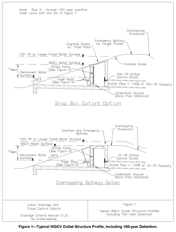
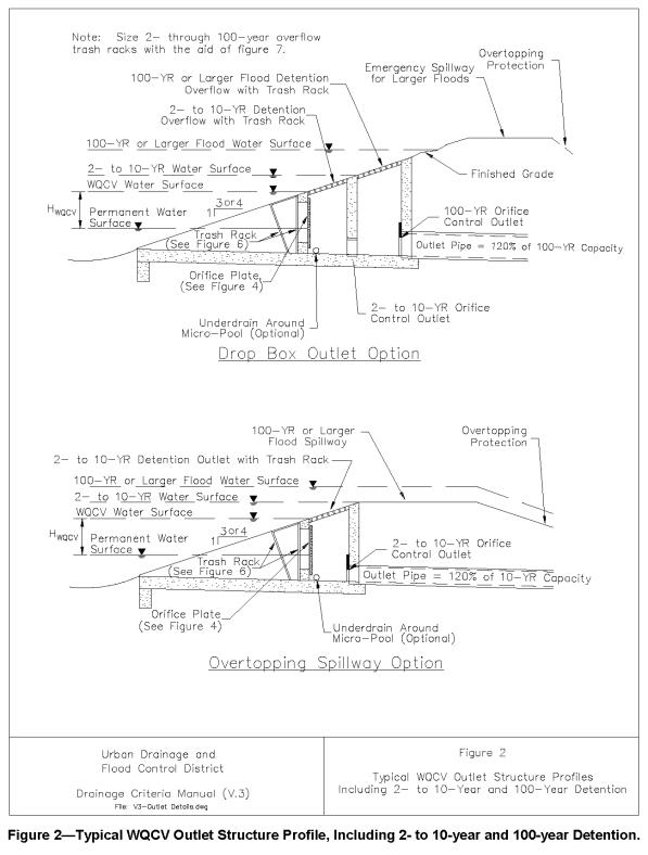
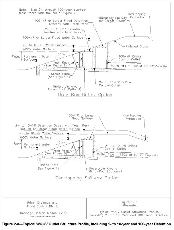
Figure EDB-1 shows a representative layout of an EDB. Although flood control storage can be accomplished by providing a storage volume above the water quality storage, how best to accomplish this is not included in this discussion. Whether or not flood storage is provided, all embankments should be protected from catastrophic failure when runoff exceeds the design event. The State Engineer’s regulatory requirements for larger dam embankments and storage volumes must be followed whenever regulatory height and/or volume thresholds are exceeded. Below those thresholds, the engineer should design the embankment-spillway-outlet system so that catastrophic failure will not occur.
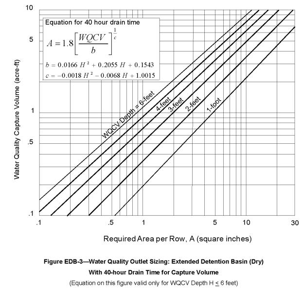
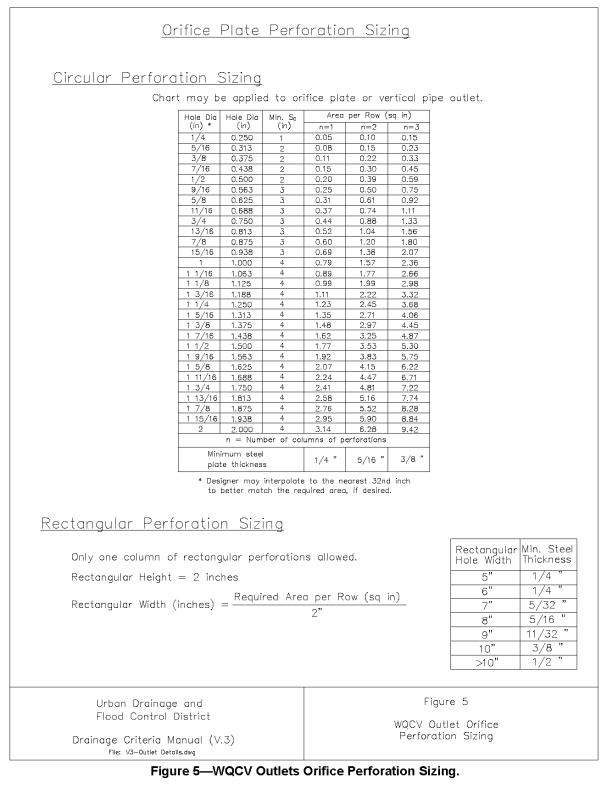
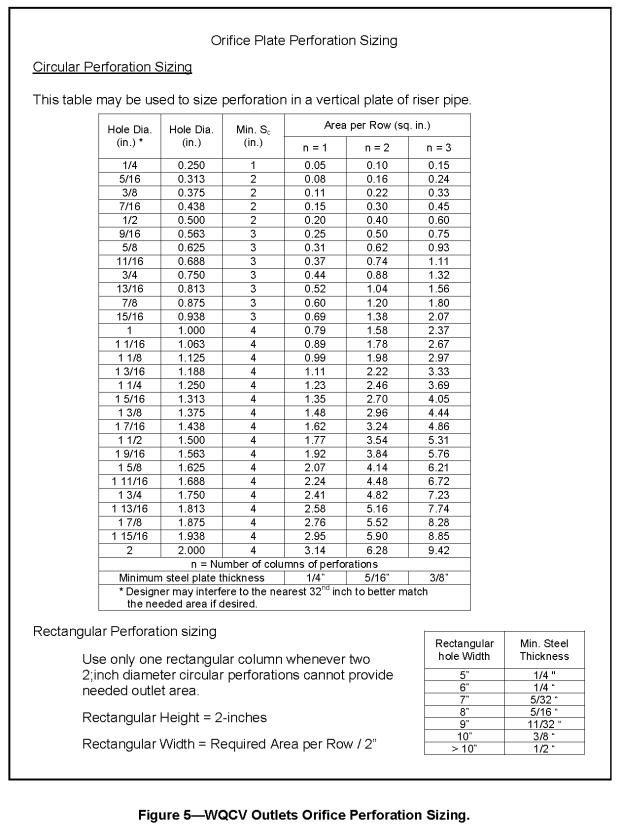
Perforated outlet and trash rack configurations are illustrated in the TYPICAL STRUCTURAL BMP DETAINS AND SPECIFICATIONS chapter. Figure EDB-3 equates the WQCV that needs to be emptied over 40 hours, to the total required area of perforations per row for the standard configurations shown in that section. The chart is based on the rows being equally spaced vertically at 4-inch centers. This total area of perforations per row is then used to determine the number of uniformly sized holes per row (see detail in the TYPICAL STRUCTURAL BMP DETAINS AND SPECIFICATIONS chapter). One or more perforated columns on a perforated orifice plate integrated into the front of the outlet can be used; however, the fewer the number of columns, the better, maximizing the size of the orifice. Using least number of columns and the largest possible orifice, reduces clogging possibilities. Other types of outlets may also be used, provided they control the release of the WQCV in a manner consistent with the drain time requirements and are approved in advance by the District.
Although the soil types beneath the pond seldom prevent the use of this BMP, they should be considered during design. Any potential exfiltration capacity should be considered a short-term characteristic and ignored in the design of the WQCV because exfiltration will decrease over time as the soils clog with fine sediment and as the groundwater beneath the basin develops a mound that surfaces into the basin. At the same time, the findings by the International BMP Database team suggest that an EDP can reduce annual runoff volume by about 30% and this finding can help justify the annual pollutant load reductions when assessing the performance of this facility.
High groundwater should not preclude the use of an EDB. Groundwater, however, should be considered during design and construction, and the outlet design must account for any upstream base flows that enter the basin or that may result from groundwater surfacing within the basin itself.
Stable, all weather access to critical elements of the pond, such as the inlet, outlet, spillway, and sediment collection areas must be provided for maintenance purposes.
6.5 Design Procedure and Criteria
The following steps outline the design procedure and criteria for an EDB.
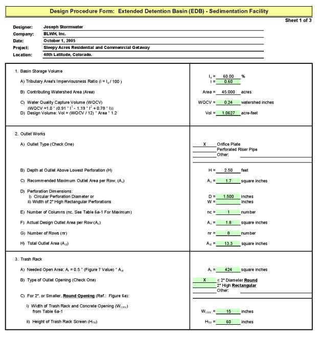
1. Basin Storage Volume
Provide a storage volume equal to 120 percent of the WQCV based on a 40-hour drain time, above the lowest outlet (i.e., perforation) in the basin. The additional 20 percent of storage volume provides for sediment accumulation and the resultant loss in storage volume.
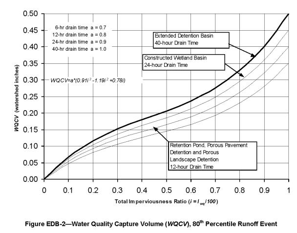
A. Determine the WQCV tributary catchment’s percent imperviousness. Account for the effects of DCIA, if any, on Effective Imperviousness. Using runoff volume reduction practices in the tributary catchment and Figure ND-1, determine the reduction in impervious area to use with WQCV calculations.
B. Find the required storage volume (watershed inches of runoff):
Determine the Required WQCV (watershed inches of runoff) using Figure EDB-2, based on the EDB’s 40-hour drain time.
Calculate the Design Volume in acre-feet as follows:
In which:
|
Area |
= |
The watershed area tributary to the extended detention pond |
|
1.2 factor |
= |
Multiplier of 1.2 to account for the additional 20% of required storage for sediment accumulation |
2. Outlet Works
The Outlet Works are to be designed to release the WQCV (i.e., not the “Design Volume”) over a 40-hour period. Refer to the TYPICAL STRUCTURAL BMP DETAINS AND SPECIFICATIONS chapter for schematics pertaining to structure geometry; grates, trash racks, and screens; outlet type: orifice plate or perforated riser pipe; cutoff collar size and location; and all other necessary components.
For a perforated outlet, use Figure EDB-3 to calculate the required area per row based on WQCV and the depth of perforations at the outlet. See the TYPICAL STRUCTURAL BMP DETAINS AND SPECIFICATIONS chapter to determine the appropriate perforation geometry and number of rows. The lowest perforations should be set at the water surface elevation of the outlet micro-pool. The total outlet area is calculated by multiplying the area per row by the number of rows.
Minimized the number of columns and maximize the perforation hole diameter when designing outlets to reduce chances of clogging by accepting the orifice site that will empty the WQCV in 36 to 44 hours.
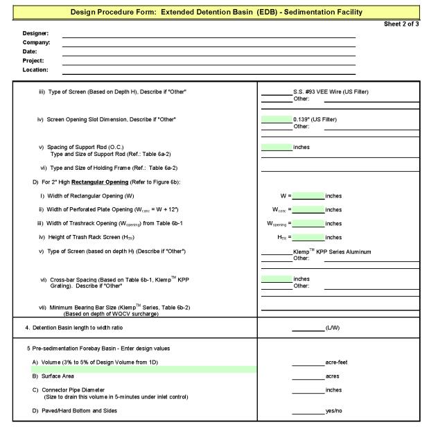
3. Trash Rack
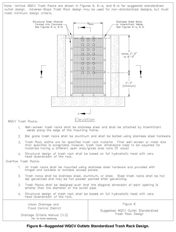
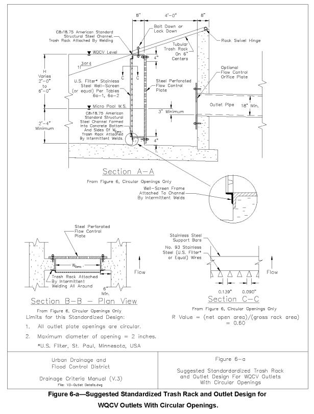
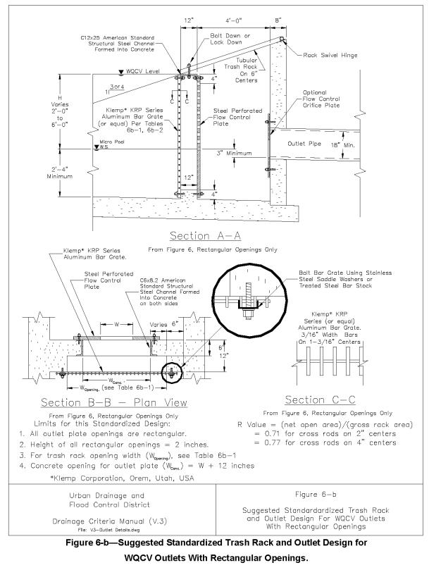
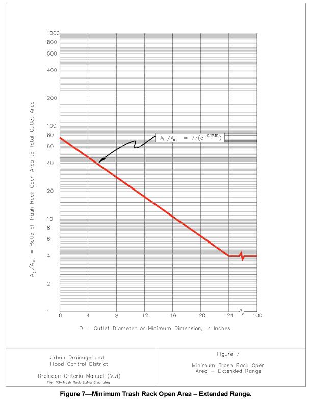
Provide a trash rack of sufficient size to prevent clogging of the primary water quality outlet. Size the rack so as not to interfere with the hydraulic capacity of the outlet. Using the total outlet area and the selected perforation diameter (or height), Figures 6, 6a or 7 in the TYPICAL STRUCTURAL BMP DETAINS AND SPECIFICATIONS chapter will help to determine the minimum open area required for the trash rack.
Use one-half of the perforated plate’s total outlet area to calculate the trash rack’s size. This accounts for the variable inundation of the outlet orifices. Figures 6 and 6a were developed as suggested standardized outlet designs for smaller sites.
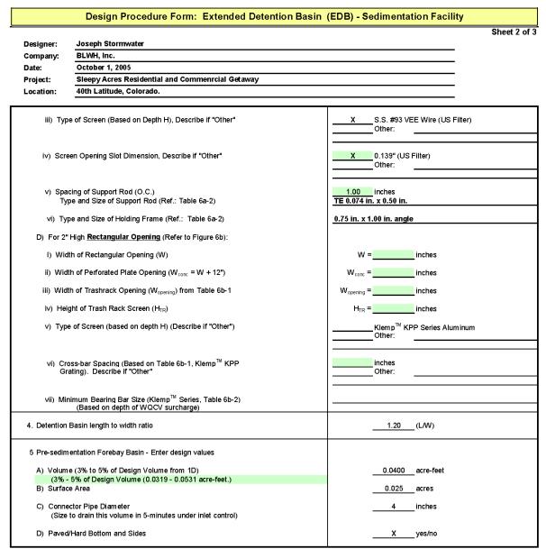
4. Basin Shape
Shape the pond whenever possible with a gradual expansion from the inlet and a gradual contraction toward the outlet, thereby minimizing short circuiting. It is best to have a basin length to width ratio between 2:1 to 3:1. To achieve this, it may be necessary to modify the inlet and outlet points through the use of pipes, swales or channels to accomplish this.
Always maximize the distance between the inlet and the outlet.
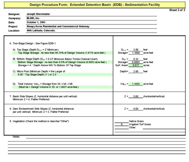
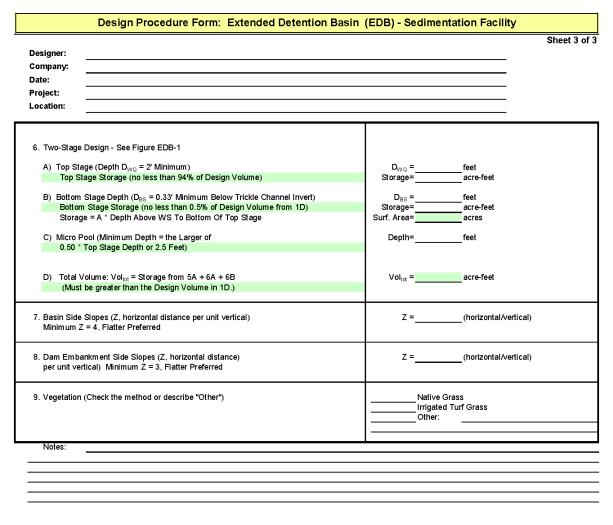
5. Two-Stage Design
A two-stage design with a pool that fills often with frequently occurring runoff minimizes standing water and sediment deposition in the remainder of the basin. The two stages are as follows:
A. Top Stage: The top stage should be one or more feet deep with its bottom sloped at 1 to 2 percent toward the trickle flow channel.
B. Bottom Stage: The dry weather water surface of the active surcharge volume of the bottom stage should be 0.5 feet or more below the bottom of the top stage, but no less than 4-inches below the invert of the upstream trickle channel, and store no less than 0.5 percent of the WQCV.
Provide a permanent micro-pool below the active storage volume of the lower stage in front of the outlet. The pool should be 1/2 the depth of the top stage depth described above, or 2.5 feet, whichever results in the larger depth.
6. Low-Flow Channel
Conveys low flows from the forebay to the bottom stage. To provide a maintainable trickle-flow channel, lining its bottom with concrete is recommended. Otherwise line its sides with buried Type VL soil riprap and bottom with concrete. Make it at least 4-inches deep if concrete lined sides and 8-inches if buried riprap sides are used. At a minimum provide capacity equal to twice the release capacity at the upstream forebay outlet.
7. Basin Side Slopes
Basin side slopes should be stable and gentle to facilitate maintenance and access. Side slopes should be no steeper than 4:1 and the use of flatter slopes is recommended; the flatter, the better and safer.
8. Dam Embankment
Design the embankment not to fail during a 100-year and larger storms. Embankment slopes should be no steeper than 3:1, preferably 4:1 or flatter, and planted with turf forming grasses. Poorly compacted native soils should be excavated and replaced. Embankment soils should be compacted to at least 95 percent of their maximum density according to ASTM D 698-70 (Modified Proctor). Spillway structures and overflows should be designed in accordance with local drainage criteria and should consider UDFCD drop-structure design guidelines.
9. Vegetation
Bottom vegetation provides erosion control and sediment entrapment. Pond bottom, berms, and side sloping areas may be planted with native grasses or with irrigated turf, depending on the local setting and needs.
10. Access
All weather stable access to the bottom, forebay, and outlet works area shall be provided for maintenance vehicles. Grades should not exceed 10 percent, and a solid driving surface of gravel, rock, concrete, gravel-stabilized turf, or Type VL soil riprap should be provided.
11. Inlet
Dissipate flow energy at pond's inflow point(s) to limit erosion and promote particle sedimentation. Inlets should be designed in accordance with UDFCD drop structure criteria, impact basin outlet details, or other types of energy dissipating structures.
12. Forebay Design
Provides an opportunity for larger particles to settle out in the inlet in an area that has a solid surface bottom to facilitate mechanical sediment removal. A rock berm or concrete-wall should be constructed between the forebay and the main EDB. The forebay volume of the permanent pool should be about 3 to 5 percent of the design WQCV. A pipe throughout the berm to convey water the main body of the EDB should be offset from the inflow streamline to prevent short circuiting and should be sized to drain the forebay volume in 3 to 5 minutes, respectively. The floor of the forebay should be concrete or grouted boulder lined to define sediment removal limits.
13. Flood Storage
Combining the water quality facility with a flood control facility is recommended. The 5-year, 10-year, 100-year, or other floods may be detained above the WQCV. See Section 1.5.5 of the BMP PLANNING FOR NEW DEVELOPMENT AND SIGNIFICANT REDEVELOPMENT chapter of this volume for further guidance.
14. Multiple Uses
When desirable and feasible, incorporate the EDB within a larger flood control basin. Also, whenever possible, try to provide for other urban uses such as active or passive recreation, and wildlife habitat. If multiple uses are being contemplated, use the multiple-stage detention basin design approach to limit inundation of passive recreational areas to one or two occurrences a year. The area within the WQCV is not suited for active recreation activities such as ballparks, playing fields, and picnic areas. These are best located above the WQCV level.
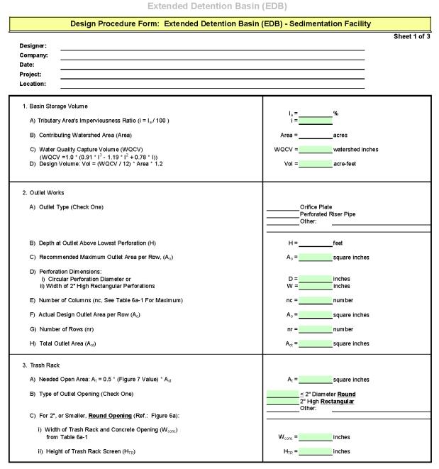
6.6 Design Example
Design forms that provide a means of documenting the design procedure are included in the DESIGN FORMS chapter. A completed form follows as a design example.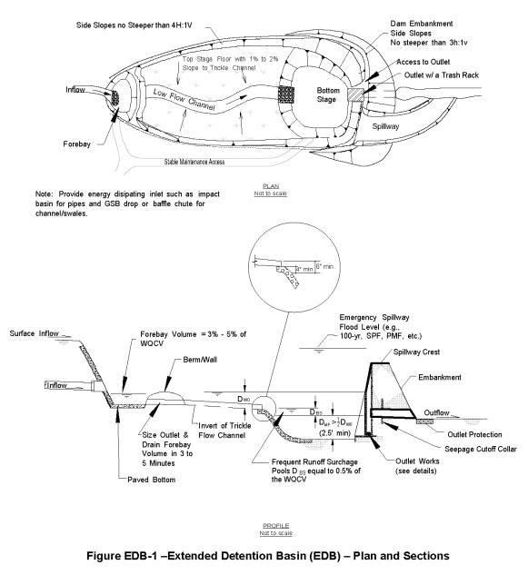
|
Maximum Dia. of Circular Opening (inches) |
Width of Trash Rack Opening (Wconc.) Per Column of Holes as a Function of Water Depth H Above Lowest Perforation |
|||||
|---|---|---|---|---|---|---|
|
H=2.0' |
H=3.0' |
H=4.0' |
H=5.0' |
H=6.0' |
Maximum Number of Columns |
|
|
≤ 0.25 |
3 in. |
3 in. |
3 in. |
3 in. |
3 in. |
14 |
|
≤ 0.50 |
3 in. |
3 in. |
3 in. |
3 in. |
3 in. |
14 |
|
≤ 0.75 |
3 in. |
6 in. |
6 in. |
6 in. |
6 in. |
7 |
|
≤ 1.00 |
6 in. |
9 in. |
9 in. |
9 in. |
9 in. |
4 |
|
≤ 1.25 |
9 in. |
12 in. |
12 in. |
12 in. |
15 in. |
2 |
|
≤ 1.50 |
12 in. |
15 in. |
18 in. |
18 in. |
18 in. |
2 |
|
≤ 1.75 |
18 in. |
21 in. |
21 in. |
24 in. |
24 in. |
1 |
|
≤ 2.00 |
21 in. |
24 in. |
27 in. |
30 in. |
30 in. |
1 |
|
NOTE: Minimum width of opening in the concrete shall not be less than 9 inches whenever above table indicated otherwise. Always minimize number of columns of perforations used. |
||||||
|
Max. Width of Opening |
Screen #93 VEE Wire Slot Opening |
Support Rod Type |
Support Rod, On‑Center, Spacing |
Total Screen Thickness |
Carbon Steel Frame Type |
|---|---|---|---|---|---|
|
9" |
0.139" |
#156 VEE |
3/4" |
0.31" |
3/8" x 1.0 flat bar |
|
18" |
0.139" |
TE .074"x.50" |
1" |
0.655" |
3/4" x 1.0 angle |
|
24" |
0.139" |
TE .074"x.75" |
1" |
1.03" |
1.0" x 1 1/2" angle |
|
27" |
0.139" |
TE .074"x.75" |
1" |
1.03" |
1.0" x 1 1/2" angle |
|
30" |
0.139" |
TE .074"x1.0" |
1" |
1.155" |
1 1/4" x 1 1/2" angle |
|
36" |
0.139" |
TE .074"x1.0" |
1" |
1.155" |
1 1/4" x 1 1/2" angle |
|
42" |
0.139" |
TE .074"x1.0" |
1" |
1.155" |
1 1/4" x 1 1/2" angle |
1 Johnson Screens, St. Paul, Minnesota USA (1-800-833-9473)
|
Maximum Width W of 2" Height Rectangular Opening (inches) |
Minimum Width of Trash Rack Opening (Wopening) as a Function of Water Depth H Above Lowest Perforation |
|||||
|---|---|---|---|---|---|---|
|
H=2.0 ft. |
H=3.0 ft. |
H=4.0 ft. |
H=5.0 ft. |
H=6.0 ft. |
Spacing of Bearing Bars, Cross Rods |
|
|
2.0 |
2.0 ft. |
2.5 ft. |
2.5 ft. |
2.5 ft. |
3.0 ft. |
1-3/16", 2" |
|
≤ 2.5 |
2.5 ft. |
3.0 ft. |
3.0 ft. |
3.5 ft. |
3.5 ft. |
1-3/16", 2" |
|
≤ 3.0 |
3.0 ft. |
3.5 ft. |
3.5 ft. |
4.0 ft. |
4.0 ft. |
1-3/16", 2" |
|
≤ 3.5 |
3.5 ft. |
4.0 ft. |
4.5 ft. |
4.5 ft. |
5.0 ft. |
1-3/16", 2" |
|
≤ 4.0 |
3.5 ft. |
4.5 ft. |
5.0 ft. |
5.0 ft. |
5.5 ft. |
1-3/16", 2" |
|
≤ 4.5 |
4.0 ft. |
4.5 ft. |
5.0 ft. |
5.5 ft. |
5.5 ft. |
1-3/16", 4" |
|
≤ 5.0 |
4.0 ft. |
5.0 ft. |
5.5 ft. |
6.0 ft. |
6.0 ft. |
1-3/16", 4" |
|
≤ 5.5 |
4.5 ft. |
5.5 ft. |
6.0 ft. |
6.5 ft. |
7.0 ft. |
1-3/16", 4" |
|
≤ 6.0 |
5.0 ft. |
6.0 ft. |
6.5 ft. |
7.0 ft. |
7.5 ft. |
1-3/16", 4" |
|
≤ 6.5 |
5.5 ft. |
6.5 ft. |
7.0 ft. |
7.5 ft. |
8.0 ft. |
1-3/16", 4" |
|
≤ 7.0 |
6.0 ft. |
7.0 ft. |
7.5 ft. |
8.5 ft. |
8.5 ft. |
1-3/16", 4" |
|
≤ 7.5 |
6.0 ft. |
7.5 ft. |
8.5 ft. |
9.0 ft. |
9.5 ft. |
1-3/16", 4" |
|
≤ 8.0 |
6.5 ft. |
8.0 ft. |
9.0 ft. |
9.5 ft. |
10.0 ft. |
1-3/16", 4" |
|
≤ 8.5 |
7.0 ft. |
8.5 ft. |
9.5 ft. |
10.0 ft. |
N/A |
1-3/16", 4" |
|
≤ 9.0 |
7.5 ft. |
9.0 ft. |
10.0 ft. |
N/A |
N/A |
1-3/16", 4" |
|
≤ 9.5 |
8.0 ft. |
9.5 ft. |
N/A |
N/A |
N/A |
1-3/16", 4" |
|
≤ 10.0 |
8.5 ft. |
10.0 ft. |
N/A |
N/A |
N/A |
1-3/16", 4" |
|
≤ 10.5 |
8.5 ft. |
N/A |
N/A |
N/A |
N/A |
1-3/16", 4" |
|
≤ 11.0 |
9.0 ft. |
N/A |
N/A |
N/A |
N/A |
1-3/16", 4" |
|
≤ 11.5 |
9.5 ft. |
N/A |
N/A |
N/A |
N/A |
1-3/16", 4" |
|
≤ 12.0 |
10.0 ft. |
N/A |
N/A |
N/A |
N/A |
1-3/16", 4" |
|
Water Depth Above Lowest Opening, H |
Minimum Bearing Bar Size, Bearing Bars Aligned Vertically |
|---|---|
|
2.0 ft. |
1" x 3/16" |
|
3.0 ft. |
1-1/4" x 3/16" |
|
4.0 ft. |
1-3/4" x 3/16" |
|
5.0 ft. |
2" x 3/16" |
|
6.0 ft. |
2-1/4" x 3/16" |
1 Klemp Corporation, Orem, Utah, USA
DESIGN EXAMPLE:
Given: A WQCV outlet plate with one column of 2 inch high by 6.5 inch wide rectangular openings.
Water Depth H = 4.5 feet above the lowest opening of and 2.5 feet below the lowest perforation.
Find: The dimensions for an aluminum bar grate trash rack.
Solution: Using Table 6b-1 for openings having a width of 6.5 inches and Water Depth H = 5 feet (i.e., rounded up from 4.5 feet). The minimum width of the concrete opening at the trash rack, Wopening, is 7'-6".
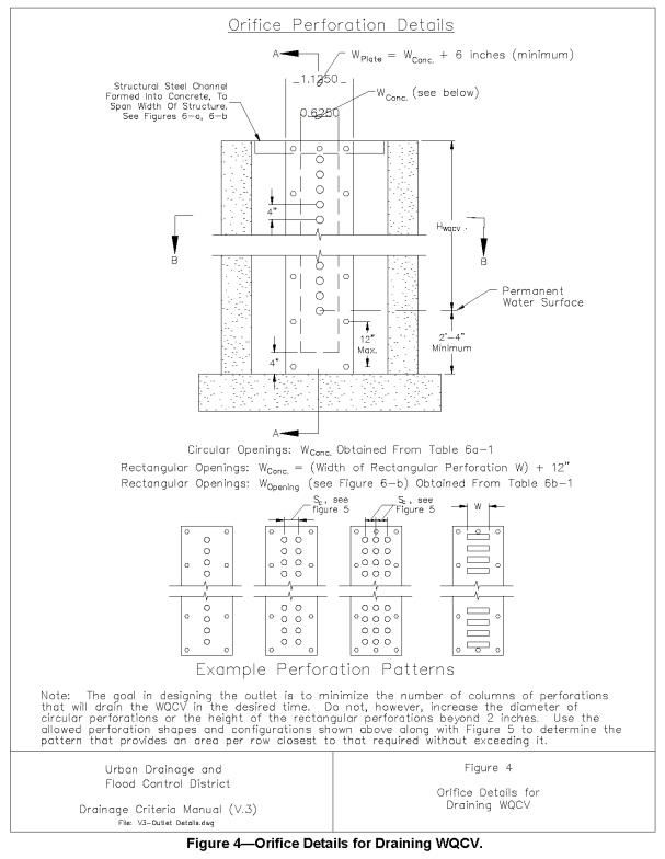
From Fig’s 4 and 5, the total width of concrete opening at the orifice plate, Wconc., is 6.5" + 12" = 18.5 inches (say 19 inches). Suggest setting the total width of the orifice plate at 26 inches.
Total minimum height of the rack structure (adding the 2-feet below the lowest row of openings to the water depth of 4.5 feet and adding 3 inches for all support channel flanges around the perimeter of the grate gives us the following total dimensions for the trash rack:
Width = 8'-0"
Height = 7'-0"
From Tables 6b-1 and 6b-2, select the ordering specifications for W = 6.5" and H = 5.0 feet or less, a 8'-0" wide by 7'-0" high trash rack using Klemp Corporation aluminum bar grate (or equal) with 2"x3/16" bearing bars spaced on 1-3/16" centers and cross rods spaced on 4" centers. Bearing bars are to be aligned vertically.
SUGGESTED TECHNICAL SPECIFICATIONS
This section contains suggested technical specifications for some of the designs contained in this Manual. These specifications may not contain many of the provisions typically seen in construction specifications such as pay item definitions and bid items. The intent that these suggested technical specifications is for the engineer to incorporate the technical portions into specific project specifications after reviewing and, if the site conditions dictate, modify them to best fit the specific site conditions of the project. When modifying these suggested specifications the engineer should maintain the general technical requirements recommended in these technical specifications.
Special Note and Disclaimer:
This information is intended for use by the design professional competent to evaluate its significance and limitation and who will accept the responsibility for its proper application. The Urban Drainage and Flood Control District and its employees disclaim any and all responsibility for any use of the information supplied herein and it is the responsibility of the user to apply and modify these guidelines as needed to meet specific site and design needs.
December 2004
|
1. |
The details shown herein are conceptual design in nature. Preparation of final design plans that address details of structural adequacy, excavation, foundation preparation, concrete work, reinforcing steel, backfill, metalwork, and appurtenances, including preparation of technical specifications, are the responsibility of the design engineer in charge of the project. |
|||
|
2. |
Alternate designs to the typical outlet structures shown herein may be considered; however, alternate designs must address the hydraulic and trash handling functional features and intent for the structures shown in this Manual. |
|||
|
3. |
Wingwalls shown herein are designed to have the structure to be backfilled to be flush with the side slopes of the basin. The use of this geometry is recommended and permits the structure to blend into the landscape most aesthetically. Other geometries may be considered, however they need to be developed with full consideration of public safety, aesthetics, maintainability, and function. The superiority of these designs should be demonstrated to be equal to or better than the design concepts shown in this Manual. |
|||
|
4. |
Permanent Water Surface refers to the water surface of the micro-pool for Extended Detention Basins and the permanent pool for Constructed Wetland Basins and Retention Ponds. |
|||
|
5. |
Perforated orifice plate shown herein is used to provide the specified drain time of the WQCV. To reduce clogging potential, it is recommended that the largest possible circular opening be selected to minimize the number of columns. The intent is to have an outlet that empties the WQCV in the time specified (e.g., 12-, 24- or 40-hours), and being within –3% to 5% of this time is considered acceptable. See Figure 4 for orifice design information. |
|||
|
6. |
Vertical Trash Rack option is preferred; however, an Adverse-Slope Trash Rack is also acceptable. Both help to shed the accumulated trash as the water level after the storm recedes. The use of a Continuous-Slope Trash Rack for WQCV outlets is not recommended. See Figure 6 for trash rack design information. |
|||
|
7. |
Drainage or flood control detention above the WQCV may be sized for any storm event specified by local stormwater criteria and not only to the 2- or 10-year events shown herein. |
|||
|
8. |
Underdrains along the perimeter of the permanent pool, including a shutoff valve, are recommended for Constructed Wetland Basins and Retention Ponds to help dewater the pool for rehabilitative maintenance. |
|||
|
9. |
When the outlet designs differ from those shown herein: |
|||
|
|
a) |
Provide needed orifices that are distributed over the vertical height of the WQCV, with the invert of the lowest orifice located at 2' 6", or more above the bottom of the micro-pool and above the bottom of Retention Ponds and Constructed Wetland Basins. |
||
|
|
b) |
Provide full hydraulic calculations demonstrating that the outlet will provide the minimum required drain time of the Water Quality Capture Volume for the BMP type being used. |
||
|
|
c) |
Outlet openings (orifices) shall be protected by trash racks having a minimum net open area specified in Fig 7. All opening dimensions shall be less than any dimension of outlet openings. |
||
|
|
d) |
Trash racks shall be manufactured from stainless steel or aluminum alloy structurally designed to not fail under a full hydrostatic load on the upstream side and assuming zero backwater depth on the downstream side. |
||
|
Urban Drainage and Flood Control District Drainage Criteria Manual (V.3) |
Typical Outlet Structure General Notes for Extended Detention Basin, Retention Pond and Constructed Wetland Basin Outlets |
|||
(Res. 40-08 (Appx. B), 3-19-08)