Chapter 12.10
ROAD STANDARDS
Sections:
Article I. General Considerations
12.10.010 Shortened designation.
12.10.030 Responsibility to provide roadway improvements.
12.10.050 WSDOT/APWA documents as primary design and construction references.
12.10.060 Other specifications.
12.10.090 Penalties and financial guarantees.
12.10.112 Interim street classification.
12.10.114 Minor technical changes.
Article II. Road Types and Geometrics
12.10.120 Road classifications.
12.10.130 Arterial and collector roads.
12.10.140 Business and local access roads.
12.10.150 Horizontal curvature and sight distance design values.
12.10.180 Cul-de-sacs and eyebrows.
12.10.190 Alleys and private access tracts.
12.10.200 Intersections and low speed curves.
12.10.210 Maximum grade and grade transitions.
12.10.220 Stopping sight distance (SSD).
12.10.230 Entering sight distance (ESD).
12.10.260 Intersections with State or federal highways.
12.10.270 Slope, wall, and drainage easements and right-of-way reduction.
12.10.280 Access and circulation requirements.
12.10.290 Traffic signals and roundabouts.
Article III. Driveways, Walks and Trails
12.10.330 Curbs, gutters and sidewalks.
12.10.340 Expansion and dummy joints.
12.10.360 Concrete steps, metal handrail and handicapped access ramps.
12.10.370 Separated walkways, bikeways and trails.
12.10.400 Equestrian facilities.
Article IV. Surfacing
12.10.410 Residential streets, pedestrian and bike.
12.10.420 Requirements for residential streets on poor subgrade.
12.10.440 Materials and lay-down procedures.
12.10.450 Pavement markings, markers, and pavement tapers.
Article V. Roadside Features
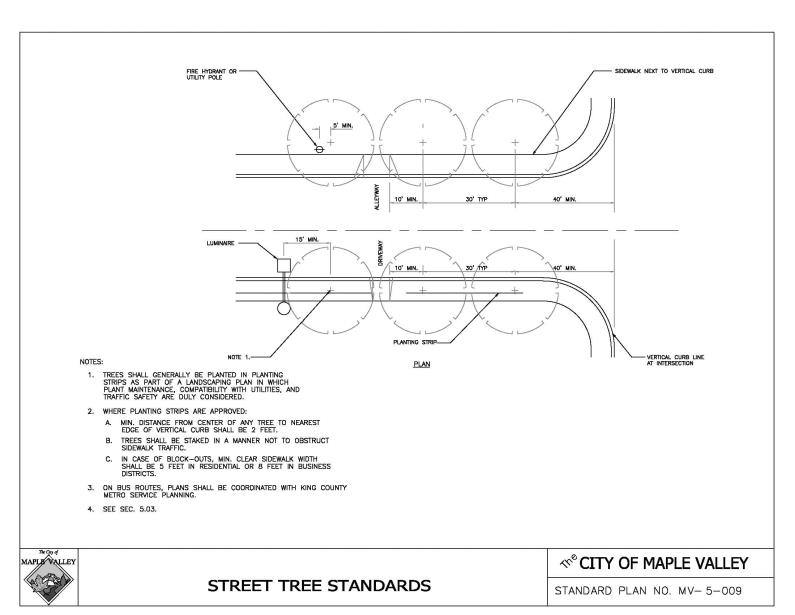
12.10.480 Street trees and landscaping.
12.10.500 Street illumination.
12.10.540 Guardrail/embankment heights.
12.10.550 Off-street parking spaces.
12.10.570 Appearance of retaining walls and steep reinforced slopes.
Article VI. Bridges
12.10.580 Principal references.
12.10.600 Bridge design criteria.
Article VII. Drainage
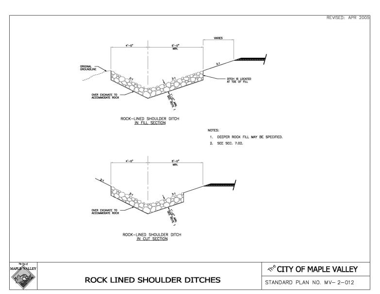
12.10.640 Storm sewers and culverts.
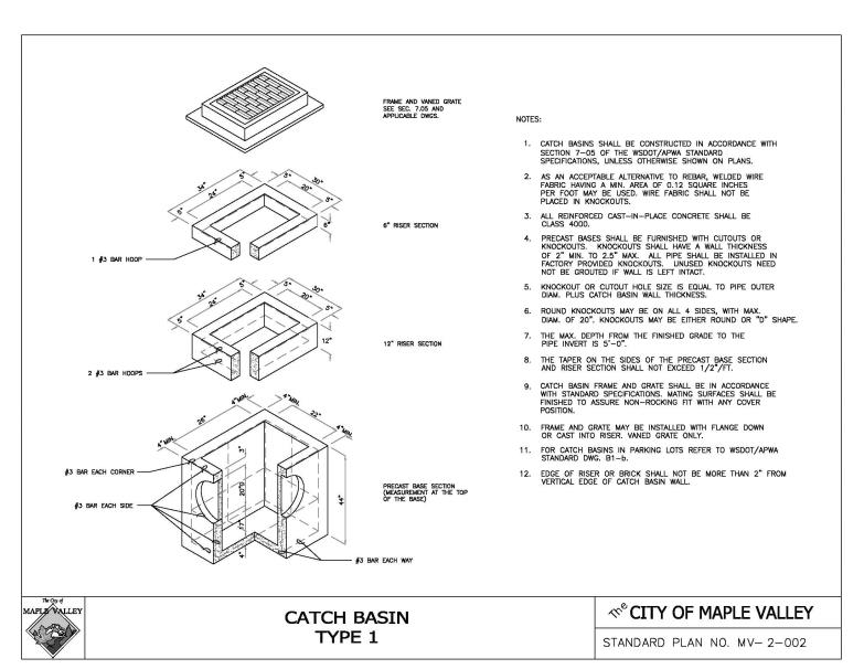
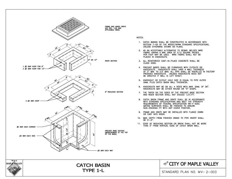
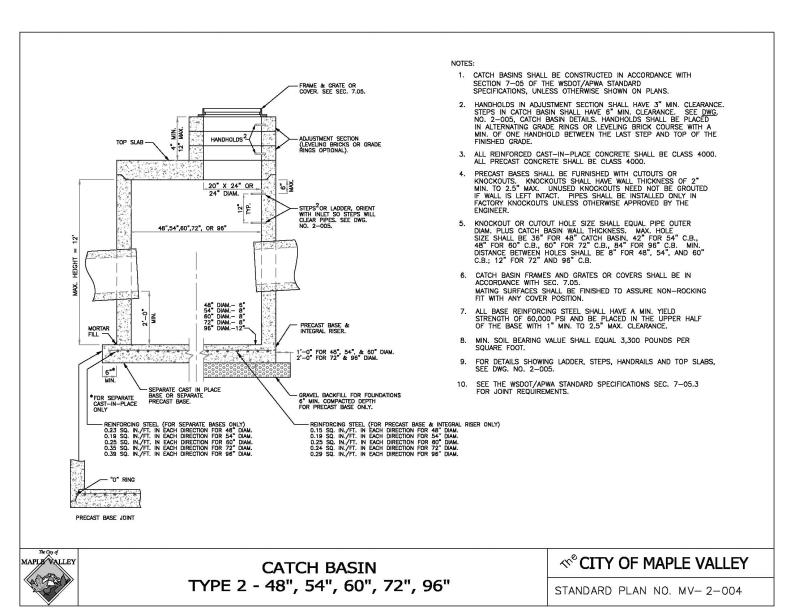
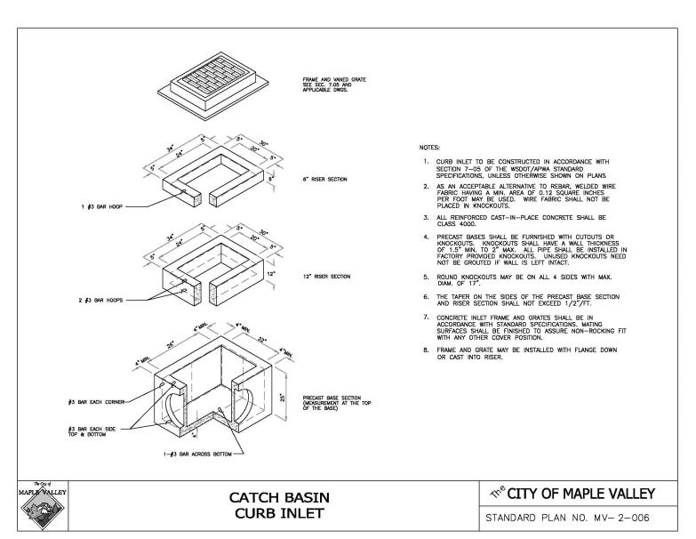
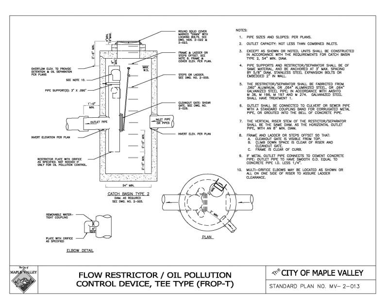
12.10.650 Catch basins and junctions.
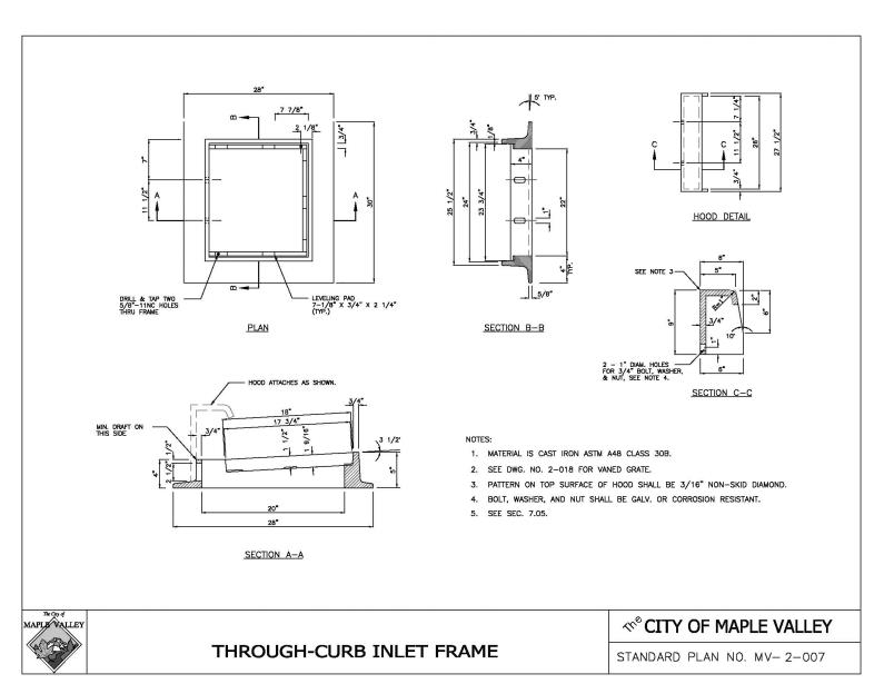
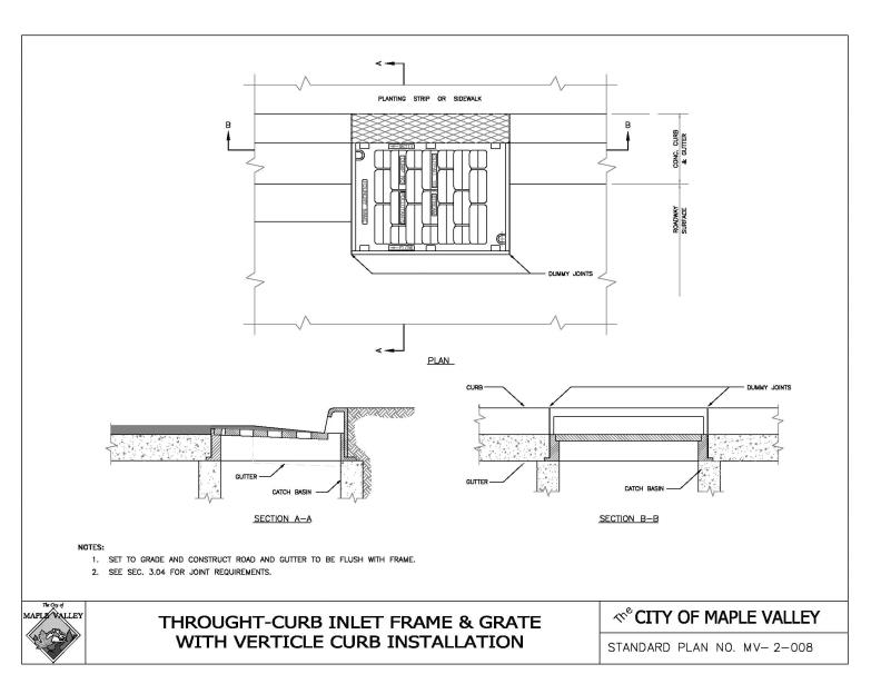
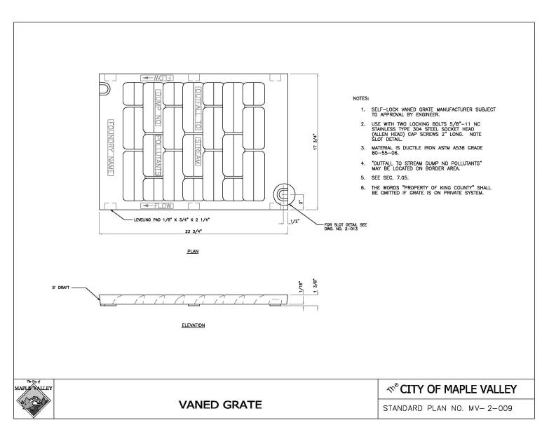
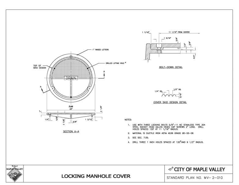
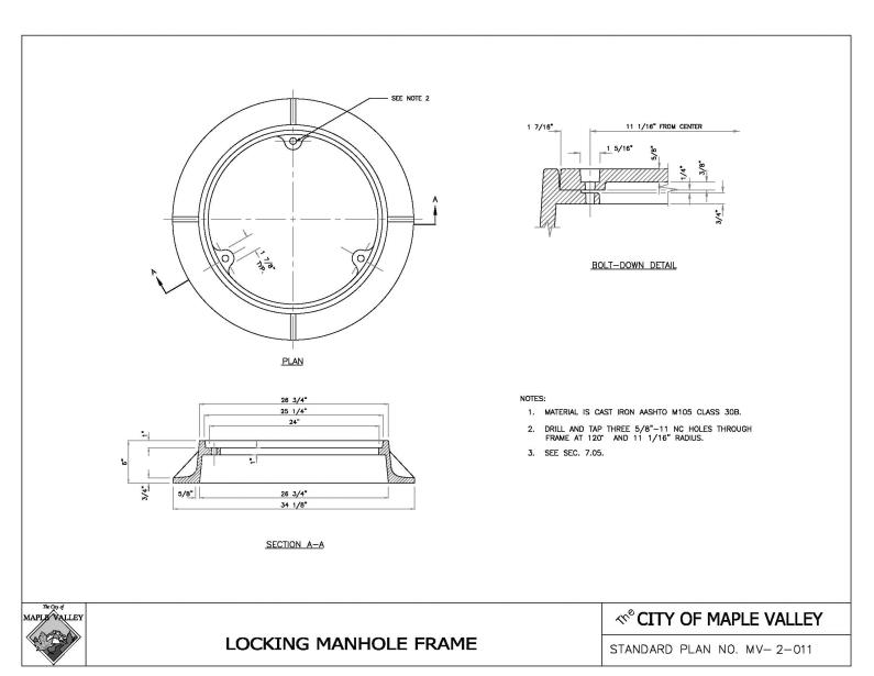
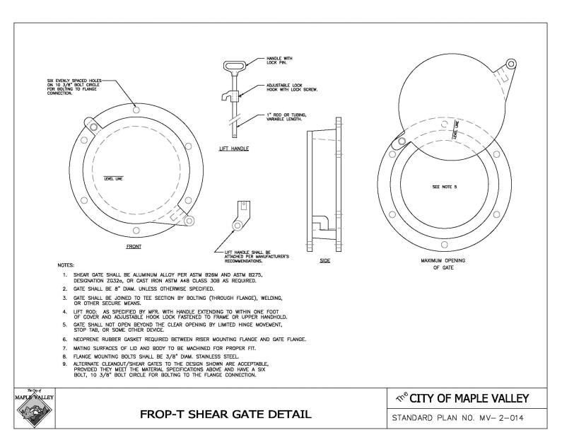
12.10.660 Frames, grates, and covers.
Article VIII. Utilities
12.10.690 Franchising policy and permit procedure.
12.10.700 Standard utility locations within the right-of-way.
12.10.710 Underground utility installation.
12.10.720 Final utility adjustment (to finish grade).
12.10.730 Final cleanup, restoration of surface drainage and erosion control.
Article IX. Construction Control and Inspection
12.10.740 Basis for control of the work.
12.10.750 Subdivision, commercial and right-of-way land use inspection.
12.10.760 Penalties for failure to notify for land use inspection.
12.10.770 Embankment construction control in developments.
12.10.780 Traffic control in development construction.
12.10.790 City forces and City contract road inspection.
12.10.800 Call before you dig.
12.10.005 Purpose.
The City of Maple Valley has adopted these road design criteria primarily to set forth specific, consistent road design elements for developers and other private parties constructing or modifying road or right-of-way facilities which require City licenses or permits.
In addition, these standards are intended to support the City’s goals for achieving affordable housing, providing adequate facilities for development in an efficient manner, complying with stormwater management and sensitive area policies and to balance these goals with the general safety and mobility needs of the traveling public.
In adopting these road standards, the City has sought to encourage standardization of road design elements where necessary for consistency and to assure so far as possible that motoring, bicycling, equestrian, and pedestrian public safety needs are met. Considerations include safety, convenience, pleasant appearance, proper drainage, and economical maintenance. The standards also provide requirements for the location and installation of utilities within the right-of-way. The City’s permitting and licensing activities require the adoption of specific, identifiable standards to guide private individuals and entities in the administrative process of procuring the necessary City approval. Yet, the City must have flexibility to carry out its general duty to provide streets, roads, and highways for the diverse and changing needs of the traveling public. Accordingly, these standards are not intended to represent the legal standard by which the City’s duty to the traveling public is to be measured.
These standards cannot provide for all situations. They are intended to assist but not to substitute for competent work by design professionals. It is expected that land surveyors, engineers, and architects will bring to each project the best of skills from their respective disciplines. These standards are also not intended to limit unreasonably any innovative or creative effort which could result in better quality, better cost savings, or both. Any proposed departure from the standards will be judged, however, on the likelihood that such variance will produce a comparable result, in every way adequate for the road user and City resident. (Ord. O-17-616 § 2 (Att. A); Ord. O-04-261 Exh. A).
Article I. General Considerations
12.10.010 Shortened designation.
The City of Maple Valley road standards will be cited routinely in the text as the “standards.” (Ord. O-17-616 § 2 (Att. A); Ord. O-04-261 Exh. A, § 1.01).
12.10.020 Applicability.
These standards shall apply prospectively to all newly constructed road and right-of-way facilities, both public and private, within the City.
These standards apply to modifications of roadway features of existing facilities which are within the scope of reconstructions, required off-site road improvements for land developments, or capital improvement projects when so required by the City or to the extent they are expressly referred to in project plans and specifications. These standards are not intended to apply to “resurfacing, restoration, and rehabilitation” projects as those terms are defined in the Local Agency Guidelines, WSDOT, as amended; however, the Public Works Director may consider the standards as optional goals.
The standards shall apply to every new placement and every planned, nonemergency replacement of existing utility poles and other utility structures within the City right-of-way, plus any requirements of City franchise agreements. (Ord. O-17-616 § 2 (Att. A); Ord. O-04-261 Exh. A, § 1.02).
12.10.025 Complete streets.
A. The City of Maple Valley will plan for, design and construct all new transportation projects to provide appropriate accommodation for bicyclists, pedestrians, transit users and persons of all abilities in comprehensive and connected network with the following exceptions:
1. Where their establishment would be contrary to public health and safety; or
2. Where there is no identified long-term need; or
3. Where there are significant adverse environmental impacts to streams, wetlands, steep slopes, or other critical areas; or
4. Where there are significant adverse impacts on neighboring land uses, including impacts from right-of-way acquisition; or
5. Where the public works director grants a documented exception which may only be authorized in specific situations where conditions warrant. Such site-specific exceptions shall not constitute general changes to the standards set in this chapter.
B. Except in unusual or extraordinary circumstances, complete streets principles may not apply to the following:
1. Repairs made pursuant to pavement opening and restoration allowed by approval of the Public Works Director.
2. Ordinary maintenance activities designed to keep assets in serviceable condition (e.g., mowing, cleaning, sweeping, spot repair and surface treatments such as chip seal, or interim measures on detour or haul routes).
C. Complete streets may be achieved through single projects or incrementally through a series of smaller improvements or maintenance activities over time. All sources of transportation funding should be drawn upon to implement complete streets. Maximum financial flexibility is important to implement complete streets principles.
D. Street design must provide for the maximum loading conditions anticipated. The width and grade of the pavement must conform to specific standards set forth herein for safety and uniformity. (Ord. O-18-640 § 1).
12.10.030 Responsibility to provide roadway improvements.
A. Any land development which will impact the service level, safety, or operational efficiency of serving roads or is required by other code or ordinance to improve such roads shall improve those roads in accordance with these standards. The City of Maple Valley shall base the extent of off-site improvements to serving roads on an assessment of the impacts of the proposed land development.
B. Any land development abutting and impacting the service level, safety, or operational efficiency of existing roads shall improve the frontage of those roads in accordance with these standards.
C. Any land development that contains internal public roads shall construct or improve those roadways to these standards.
D. It is the City’s practice to not allow subdivisions to be recorded unless there exists a recorded continuous public access to the subdivision except as provided for in MVMC 12.10.160. Nor will the City accept a road for maintenance until the road is directly connected to a City or other publicly maintained road.
E. All road improvement and development projects shall include pedestrian access as a part of the design. Where existing roadways are to be modified, pedestrian facilities shall be as described in MVMC 12.10.320, 12.10.370, 12.10.380 or 12.10.390.
F. Low impact development shall be considered as the preferred approach to roadway improvements to reduce flooding, improve water quality, and mitigate new or replaced impervious surfaces. (Ord. O-17-616 § 2 (Att. A); Ord. O-04-261 Exh. A, § 1.03).
12.10.040 General references.
The standards implement and are intended to be consistent with:
A. Maple Valley Municipal Code, as amended, including:
1. Title 10, Traffic;
2. Title 12, Streets, Sidewalks, and Public Places;
3. Title 13, Water and Sewers;
4. Title 14, Environment;
5. Title 15, Building and Construction;
6. Title 16, Planning and Development;
7. Title 17, Subdivisions;
8. Title 18, Development Regulations.
B. Implementing guidelines on drainage prepared by Surface Water Management Division, King County Department of Public Works, and hereafter referred to as the “Surface Water Design Manual.”
C. City of Maple Valley Comprehensive Plan 1999, as updated.
D. Maple Valley Surface Water Master Plan. (Ord. O-17-616 § 2 (Att. A); Ord. O-04-261 Exh. A, § 1.04).
12.10.050 WSDOT/APWA documents as primary design and construction references.
Except where these standards provide otherwise, design detail, construction workmanship, and materials shall be in accordance with the following publications produced separately by the Washington State Department of Transportation (WSDOT), or jointly by WSDOT and the Washington State Chapter of American Public Works Association (APWA):
A. WSDOT/APWA Standard Specifications for Road, Bridge, and Municipal Construction, current edition as amended. These will be referred to as the “WSDOT/APWA Standard Specifications.”
B. The WSDOT/APWA Standard Plans for Road and Bridge Construction, to be referred to as the “WSDOT/APWA Standard Plans,” current edition as amended.
C. WSDOT Design Manual, current edition as amended. (Ord. O-17-616 § 2 (Att. A); Ord. O-04-261 Exh. A, § 1.05).
12.10.060 Other specifications.
The following shall be applicable when pertinent, when specifically cited in these standards or when required by State or federal funding authority:
A. Local Agency Guidelines, WSDOT, as amended.
B. Guidelines for Urban Arterial Program, WSDOT, as amended.
C. Design criteria of federal agencies include the Federal Housing Administration, Department of Housing and Urban Development; and the Federal Highway Administration, Department of Transportation.
D. A Policy on Geometric Design of Highways and Streets, American Association of State Highway and Transportation Officials (AASHTO), 1984, or current edition when adopted by WSDOT.
E. Standard Specifications for Highway Bridges, adopted by AASHTO, current edition.
F. U.S. Department of Transportation Manual on Uniform Traffic Control Devices, “MUTCD,” as amended and approved by the Washington State Department of Transportation, current edition.
G. Guide for the Development of Bicycle Facilities, adopted by AASHTO, current edition.
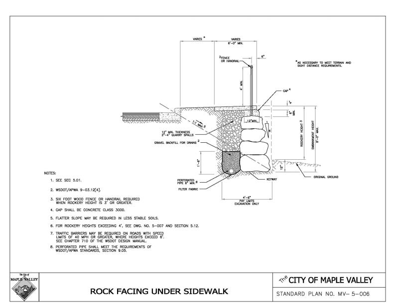
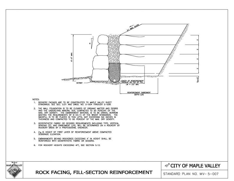
H. Associated Rockery Contractors, Standard Rock Wall Construction Guidelines.
I. American Society for Testing and Materials (ASTM). (Ord. O-17-616 § 2 (Att. A); Ord. O-04-261 Exh. A, § 1.06).
12.10.070 Road plans.
Plans for roads and road drainage shall be prepared and submitted consistent with these standards and the City of Maple Valley Municipal Code. An exception to this requirement may be granted if the following criteria are met:
A. No more than 5,000 square feet will be cleared and graded within the right-of-way or easement; and
B. The existing grade or slope in the road right-of-way or easement does not exceed 12 percent; and
C. The work will not intercept a stream or wetland or otherwise impact natural surface drainage as set forth in the Maple Valley Municipal Code regarding sensitive areas and the Surface Water Design Manual; and
D. City standard drawings, submitted with required permits, are sufficient to describe the improvement to be constructed and are approved by the Director. (Ord. O-17-616 § 2 (Att. A); Ord. O-04-261 Exh. A, § 1.07).
12.10.080 Variances.
Repealed by Ord. O-09-395. (Ord. O-04-261 Exh. A, § 1.08).
12.10.085 Variances.
A. A variance is required for any design or construction deviation from these standards. The variance application form is available from the Department of Public Works. There are two types of variances. A variance request that involves deviation from road geometrics is considered categorically different from a variance request involving driveways, surfacing, or roadway features. Because road geometrics were adopted to be consistent with State and federal guidelines, careful consideration and attention to public safety concerns must occur with any request for a variance from road geometrics.
Variances may be granted by the Public Works Director upon evidence that such variances are in the public interest and that requirements for safety, function, fire protection, appearance and maintainability based upon sound engineering judgment are fully met. Any anticipated variances from these standards that do not meet the Uniform Fire Code shall also require review and concurrence by the Maple Valley Fire Marshal.
1. Variance for Road Geometrics. Variance requests that involve deviations from road geometrics, as set forth in Article II of this chapter, should be requested at the time of submission of an application for land use review and in all cases must be submitted prior to the City’s decision on the underlying land use application. Variances for road geometrics will not be considered after the City has rendered a decision on the underlying land use application.
a. The variance decision will be made by the Public Works Director or designee. The Public Works Director’s decision will be forwarded to the Director of Community Development for inclusion in the City’s decision or recommendation on the underlying land use application.
b. Any appeal of a variance request involving road geometrics shall be governed by the appeal process for the underlying land use application and must be appealed during the appeal period for the land use application.
2. Variance for Other Road Standards (Not Road Geometrics). Requests for variance that involve consideration of Articles III, IV, V, VI, VII and VIII of this chapter may be submitted at any time prior to construction approval.
a. The Public Works Director shall make the decision on a variance request.
b. There is no appeal of a decision on a variance request involving consideration of Articles III, IV, V, VI, VII and VIII of this chapter.
3. For a City-initiated public works project in which a variance is necessary, the designated project engineer will submit an application for variance to the Public Works Director for a decision.
B. Questions regarding interpretation of these standards may be directed to the Public Works Department or the Community Development Department. Formal code interpretations are governed by MVMC 18.10.020.
C. Following the expiration of the appeal period of any applicable land use action or decision for the underlying land use application, the Public Works Director shall notify the Maple Valley City Council of any approved variance request. (Ord. O-17-616 § 2 (Att. A); Ord. O-09-395 § 2).
12.10.090 Penalties and financial guarantees.
Failure to comply with these standards may result in denial of plan or development permit approval, revocation of prior approvals, legal action for forfeiture of financial guarantee, code enforcement, and/or other penalties as provided by law.
A. Construction Performance Guarantees. Any construction work on the right-of-way (both maintained and unmaintained) other than capital improvement projects or maintenance work shall be guaranteed by a financial guarantee. All work on private road and drainage facilities required as a condition of a City approval process shall be guaranteed by a financial guarantee at the time of plat recording. The City shall determine the amount and form of the financial guarantee.
B. Maintenance Performance Guarantees. The successful performance of the right-of-way improvements shall be guaranteed for a period of two years from the latest date of either the acceptance or final construction approval. The City of Maple Valley shall determine the amount and form of the maintenance financial guarantee. The minimum maintenance guarantee shall be $1,000. Maintenance guarantees will not be required when the required performance guarantee is $1,000 or less. (Ord. O-17-616 § 2 (Att. A); Ord. O-04-261 Exh. A, § 1.09).
12.10.100 Meaning of terms.
“ADA” means the Americans with Disabilities Act.
“ADT” means average daily traffic.
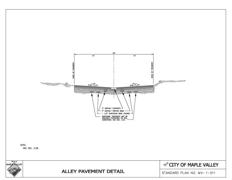
“Alley” means a thoroughfare or right-of-way, usually narrower than a street, which provides access to the rear boundary of two or more residential properties and is not intended for general traffic circulation; privately maintained.
“Auxiliary lane” means the portion of the roadway adjoining the traveled way for parking, turning or other purposes supplementary to through-traffic movement.
“Bridge” means a structure with a span greater than 20 feet in width.
“Bulb” means a round area for vehicle turnaround typically located at the end of a cul-de-sac street.
“City” means the City of Maple Valley.
“Council” means the City Council of Maple Valley.
“Cul-de-sac” means a short street having one end open to traffic and the other temporarily or permanently terminated by a vehicle turnaround.
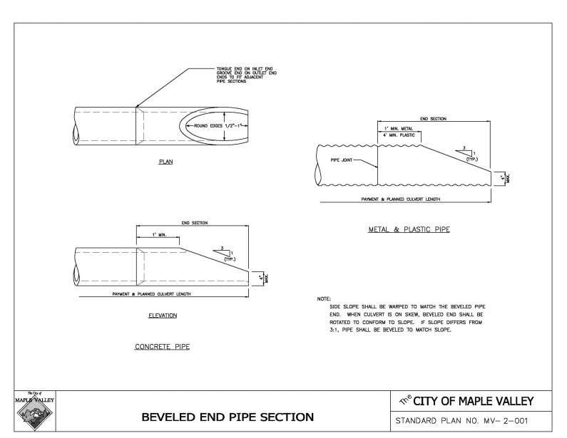
“Culvert” means a pipe or similar element with a span/diameter less than 20 feet.
“Design speed” means the speed approved by the City of Maple Valley or the Engineer for the design of the physical features of a road as established by MVMC 12.10.140 for neighborhood access streets or equal to 10 miles per hour above the current or expected posted speed limit for arterials.
“Developer” means any person, firm, partnership, association, joint venture or corporation or any other entity who undertakes to improve residential, commercial, or industrial property or to subdivide for the purpose of resale and profit.
“Director” means the Public Works Director, City of Maple Valley.
“Driveway” means a privately maintained access to no more than two residential, commercial or industrial properties.
“Engineer” means the Public Works Director or Engineer, having authorities specified in RCW 36.75.050 and Chapter 36.80 RCW, or his/her authorized representative.
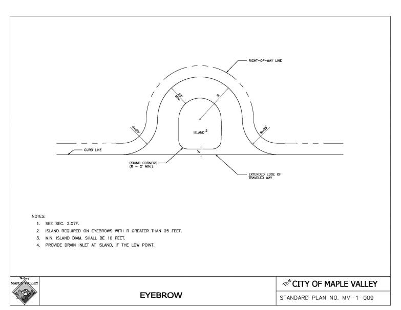
“Eyebrow” means a partial bulb located adjacent to the serving road that provides access to lots and serves as a vehicle turnaround.
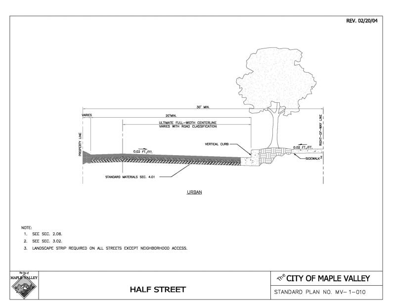
“Half street” means a street constructed along edge of development, utilizing a portion of the regular width of right-of-way and permitted as an interim facility pending construction of the other half of the street by the adjacent owner.
“Joint-use driveway tract” means a jointly owned and maintained tract or easement serving two properties.
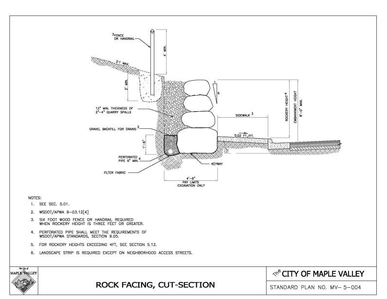
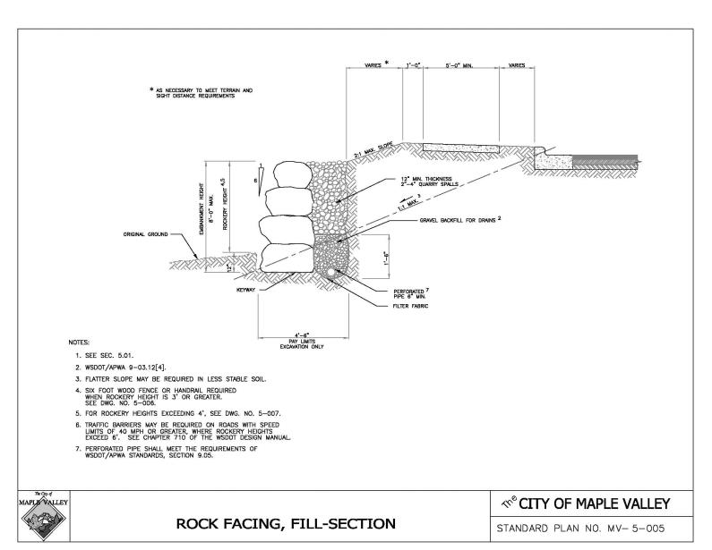
“Keyway” means a shallow trench of minimum 12-inch depth for rockery and slightly inclined toward the face being protected.
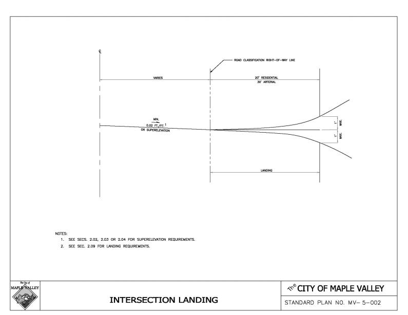
“Landing” means a road or driveway approach area to any public or private road.
“Landscape strip” means the ground area planted with permanent vegetation within the street right-of-way located between the back of curb and sidewalk or the back of curb and the right-of-way line.
“Loop” means a road of limited length forming a loop, having no other intersecting road, and functioning mainly as direct access to abutting properties. A loop may be designated for one-way or two-way traffic.
“Low impact development” means a stormwater and land use management strategy that strives to mimic predisturbance hydrologic processes of infiltration, filtration, storage, evaporation, and transpiration by emphasizing conservation, use of on-site natural features, site planning, and distributed stormwater management practices that are integrated into a project design.
“Off-street parking space” means an area accessible to vehicles, exclusive of roadways, sidewalks, and other pedestrian facilities, that is improved, maintained and used for the purpose of parking a motor vehicle.
“Pavement width” means a paved area or paved surface between curb, or gutter flow line roads as depicted on Drawings No. MV-1-001 through MV-1-011.
“Pipe stem” means a strip of land having a width narrower than that of the lot or parcel to be served and is designed for providing access to that lot or parcel.
“Private access tract” means a privately owned and maintained tract providing vehicular access to six or fewer residential properties.
“Private street” means a privately owned and maintained access provided for by a tract, easement or other legal means.
“Professional engineer” means a professional civil engineer licensed to practice in the State of Washington.
“Public street” means a publicly owned facility providing access, including the roadway and all other improvements, inside the right-of-way.
“Public Works Director” means the individual designated by the City Manager to direct the activities of the Department of Public Works.
“Right-of-way” means land, property, or property interest (e.g., an easement), usually in a strip, acquired for or devoted to transportation purposes.
“Road” means a facility providing public or private access including the roadway and all other improvements inside the right-of-way. “Road” and “street” will be considered interchangeable terms for the purpose of these standards.
“Roadway” means pavement width plus shoulders.
“Shoulder” means the paved or unpaved portion of the roadway outside the traveled way that is available for emergency parking or nonmotorized use.
“Traffic Engineer” means the Public Works Director or appointee responsible for design, operation and maintenance of traffic control devices as defined by WAC 308-330-260 and 308-330-265.
“Traveled way” means the part of the road made for vehicle travel excluding shoulders and auxiliary lanes.
“Utility” means a company providing public service such as gas, electric power, telephone, telegraph, water, sewer, or cable television, whether or not such company is privately owned or owned by a governmental entity. (Ord. O-17-616 § 2 (Att. A); Ord. O-04-261 Exh. A, § 1.10).
12.10.110 Severability.
If any part of these road standards as established by ordinance shall be found invalid, all other parts shall remain in effect. (Ord. O-17-616 § 2 (Att. A); Ord. O-04-261 Exh. A, § 1.11).
12.10.112 Interim street classification.
The Director of Public Works shall determine which classification under the newly adopted street standards shall apply to each of the City’s current street classifications during the interim period between the effective date of the ordinance codified in this chapter and reclassification of the City’s streets under the 2004 Comprehensive Plan update. (Ord. O-17-616 § 2 (Att. A); Ord. O-04-261 § 3).
12.10.114 Minor technical changes.
The City of Maple Valley Public Works Director is hereby authorized to make minor changes to these road standards as necessary to maintain this chapter in conformance with future amendments to the Washington State Department of Transportation and Washington State Chapter of American Public Works Association design standards set forth in MVMC 12.10.050. The Public Works Director shall promptly report any such modifications to the City Council for ratification. (Ord. O-17-616 § 2 (Att. A); Ord. O-04-261 § 4).
Article II. Road Types and Geometrics
12.10.120 Road classifications.
City roads are classified functionally as indicated in MVMC 12.10.130 and 12.10.140. Function is the controlling element for classification and shall govern right-of-way, road width and road geometrics. Other given elements such as access, arterial spacing and average daily traffic count (ADT) are typical. (Ord. O-17-616 § 2 (Att. A); Ord. O-04-261 Exh. A, § 2.01).
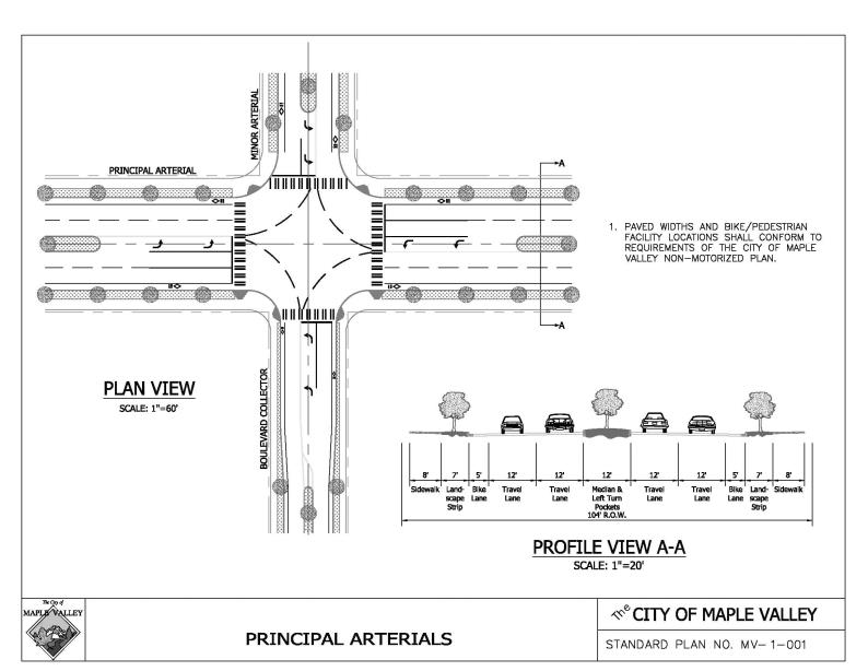
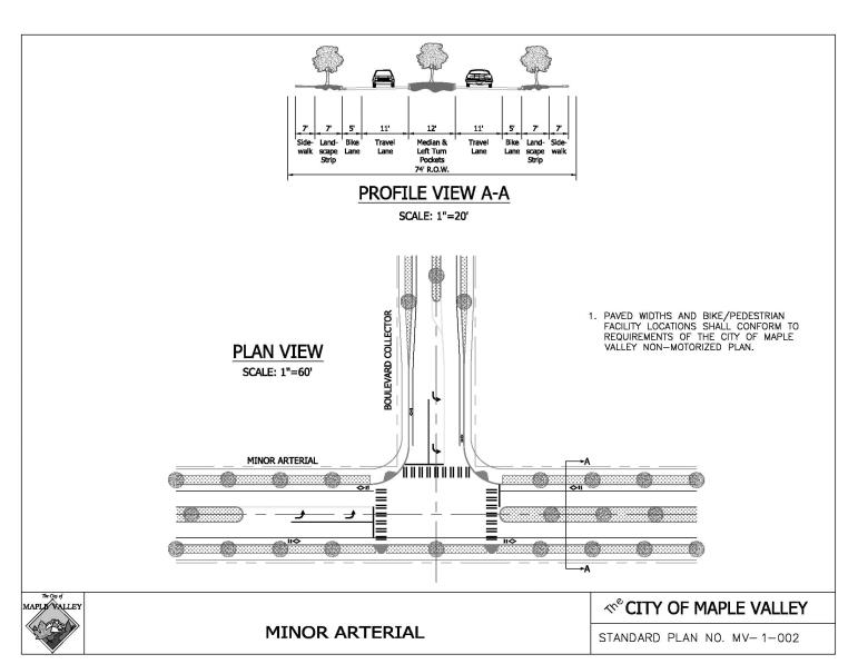
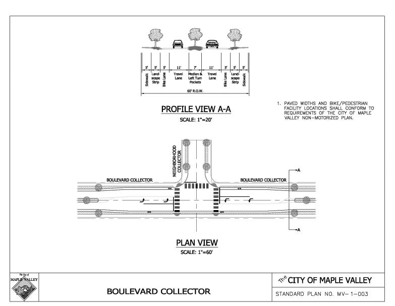
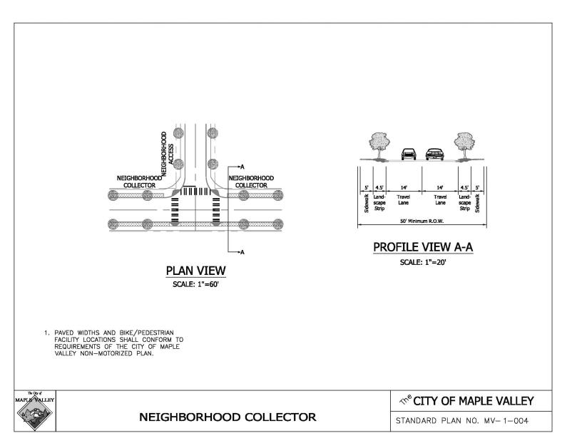
12.10.130 Arterial and collector roads.1
Comprising the City primary road system; see Drawings No. MV-1-001 and MV-1-004.
|
CLASSIFICATION |
PRINCIPAL ARTERIAL |
MINOR ARTERIAL |
BOULEVARD COLLECTOR |
NEIGHBORHOOD COLLECTOR |
|
|---|---|---|---|---|---|
|
FUNCTION |
Intercommunity streets connecting largest community centers and facilities. |
Intracommunity streets connecting community centers and facilities. |
Intracommunity street with landscaped median connecting residential neighborhoods with centers and facilities. |
Intracommunity streets connecting residential neighborhoods with centers and facilities. |
|
|
Access |
Controlled with very restricted access to abutting properties. |
Partially controlled with infrequent access to abutting properties. |
Partially controlled with infrequent access to abutting properties. |
Partially controlled with infrequent access to abutting properties. |
|
|
Typical Spacing |
2 to 5 Miles |
Under 2 Miles |
Under 2 Miles |
Under 2 Miles |
|
|
Average Daily Traffic |
Over 2,000 |
Over 2,000 |
Under 2,000 |
Under 2,000 |
|
|
CRITERIA |
|
|
|
|
|
|
A. Typical Road Type |
Curb |
Curb |
Curb |
Curb |
|
|
B. Design Speed2 (MPH) |
Varies 40 – 60 |
Varies 40 – 50 |
Varies 35 – 45 |
Varies 35 – 40 |
|
|
C. Standard Superelevation (Ft./Ft.) |
0.06 |
0.06 |
0.06 |
0.06 |
|
|
D. Horizontal Curvature |
See Table 2.1, MVMC 12.10.150 |
See Table 2.1, MVMC 12.10.150 |
See Table 2.1, MVMC 12.10.150 |
See Table 2.1, MVMC 12.10.150 |
|
|
E. Maximum Grade (%)3 |
9 |
10 |
10 |
10 |
|
|
F. Standard Stopping Sight Distance (Ft.)4 |
See Table 2.1, MVMC 12.10.150 |
See Table 2.1, MVMC 12.10.150 |
See Table 2.1, MVMC 12.10.150 |
See Table 2.1, MVMC 12.10.150 |
|
|
G. Standard Entering Sight Distance (Ft.)5 |
See Table 2.1, MVMC 12.10.150 |
See Table 2.1, MVMC 12.10.150 |
See Table 2.1, MVMC 12.10.150 |
See Table 2.1, MVMC 12.10.150 |
|
|
H. Minimum Passing Sight Distance on 2-Lane Road (Ft.) |
See Table 2.1, MVMC 12.10.150 |
See Table 2.1, MVMC 12.10.150 |
See Table 2.1, MVMC 12.10.150 |
See Table 2.1, MVMC 12.10.150 |
|
|
I. Minimum Traveled Way (Ft.)6 |
2/3-Lane |
N/A |
32 |
32 |
28 |
|
|
5-Lane |
56 |
N/A |
N/A |
N/A |
|
J. Minimum Roadway Width (Ft.)6 |
2/3-Lane |
N/A |
44 |
39 |
28 |
|
|
5-Lane |
68 |
N/A |
N/A |
N/A |
|
K. Minimum Right-of-Way Width (Ft.) |
2/3-Lane |
N/A |
74 |
60 |
50 |
|
|
5-Lane |
104 |
N/A |
N/A |
N/A |
|
L. Type of Curb |
Vertical Curb and Gutter |
Vertical Curb and Gutter |
Vertical Curb and Gutter |
Vertical Curb and Gutter |
|
|
M. NOTES: 1. Within the above parameters, geometric design requirements shall be determined for specific roads. (See MVMC 12.10.050.) 2. Design speed is a basis for determining geometric elements and does not imply posted or legally permissible speed. Curves shall be designed within parameters of B, C and D above. (See MVMC 12.10.150.) 3. Maximum grade may be exceeded for short distances. (See MVMC 12.10.210.) 4. Standard stopping sight distance (SSD) shall apply unless otherwise approved by the Public Works Director. (See MVMC 12.10.220.) 5. Standard entering sight distance (ESD) shall apply at intersections and driveways unless otherwise approved by the Public Works Director. (See MVMC 12.10.230.) 6. Criteria for State and federal funding may require greater width. 7. Neighborhood collectors intersecting with arterials shall be 36 feet wide for the first 150 feet. See MVMC 12.10.450 for tapers. 8. Curb cuts are allowed in vertical curb and gutter systems as approved by the engineer. |
|||||
(Ord. O-17-616 § 2 (Att. A); Ord. O-04-261 Exh. A, § 2.02).
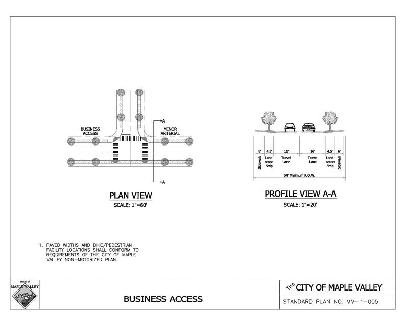
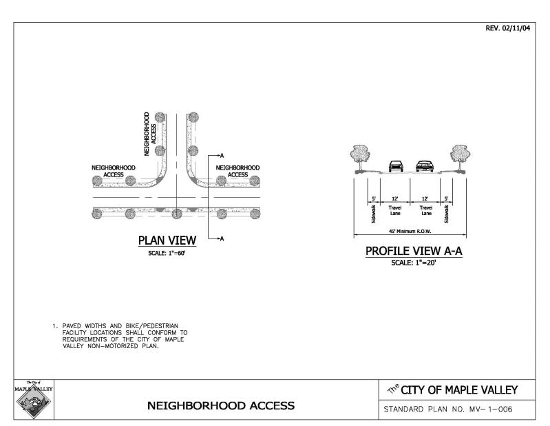
12.10.140 Business and local access roads.1
See Drawings No. MV-1-005 through MV-1-007.
|
LOCAL ACCESS STREETS |
|||
|---|---|---|---|
|
CLASSIFICATION |
BUSINESS ACCESS |
NEIGHBORHOOD ACCESS |
CUL-DE-SAC |
|
FUNCTION |
Local street abutting business, service, office and professional activities. |
Streets providing circulation within neighborhoods typically connecting to neighborhood collectors. |
Permanent cul-de-sacs, or short loops2, connecting to neighborhood access streets and not supportive of through traffic. |
|
Access |
As needed with some restrictions. |
As needed with some restrictions. |
As needed with only minimal restrictions. |
|
Serving Potential Number of Single-Family Dwelling Units8 |
N/A |
100 Max.3 |
50 Max. |
|
CRITERIA |
|
|
|
|
A. Typical Road Type |
Curb |
Curb |
Curb |
|
B. Design Speed4 (MPH) |
35 |
25 |
Low Speed Curve. See MVMC 12.10.200 |
|
C. Max. Superelevation (Ft./Ft.) |
0.06 |
See MVMC 12.10.150(B) |
See MVMC 12.10.150(B) |
|
D. Horizontal Curvature Min. Radius (Ft.) |
See Table 2.1, MVMC 12.10.150 |
See Table 2.2, MVMC 12.10.150 |
Low Speed Curve. See MVMC 12.10.200 |
|
E. Max. Grade5 |
10 |
12 |
12 |
|
F. Standard Stopping Sight Distance (Ft.)6 |
See Table 2.1, MVMC 12.10.150 |
See Table 2.2, MVMC 12.10.150 |
150 ft. |
|
G. Standard Entering Sight Distance (Ft.)7 |
See MVMC 12.10.230 |
See MVMC 12.10.230 |
See MVMC 12.10.230 |
|
H. Min. Pavement Width (Ft.) |
32 |
24 |
24 |
|
I. Min. Roadway Width (Ft.) |
32 |
24 |
24 |
|
J. Min. Right-of-Way Width Total (Ft.) |
54 |
45 |
50 Bulb |
|
K. Min. Half St. Paved Width (Ft.) |
See MVMC 12.10.170 |
See MVMC 12.10.170 |
N/A |
|
L. Min. One-Way Paved Width Total (Ft.) |
22 |
16 |
N/A |
|
M. Type of Curb |
Vertical Curb and Gutter |
Vertical Curb and Gutter |
Vertical Curb and Gutter |
1. Within the above parameters, geometric design for specific streets shall be consistent with AASHTO Policy on Geometric Design of Highways and Streets.
2. See MVMC 12.10.240 for one-way loops.
3. See MVMC 12.10.280 for residential access connection requirements.
4. Design speed is a basis for determining geometric elements and does not imply posted or legally permissible speed. Curves shall be designed within parameters of B, C and D above. (See MVMC 12.10.160.)
5. Maximum grade may be exceeded for short distances. (See MVMC 12.10.210.)
6. Standard stopping sight distance (SSD) shall apply unless otherwise approved by the Public Works Director. (See MVMC 12.10.220.)
7. Standard entering sight distance (ESD) shall apply at intersections and driveways on neighborhood collectors unless otherwise approved by the Public Works Director. (See MVMC 12.10.230.)
8. Maximum number of dwelling units being served by the street may be reduced by the Public Works Director to a number necessary for traffic safety if the street or streets connecting the proposed street to an arterial street do not meet minimum pavement widths.
(Ord. O-17-616 § 2 (Att. A); Ord. O-04-261 Exh. A, § 2.03).
12.10.150 Horizontal curvature and sight distance design values.
A. The design values shown in Tables 2.1 and 2.2 are minimum values necessary to meet the requirements of MVMC 12.10.130 and 12.10.140 for a selected design speed and road classification. A maximum of eight percent superelevation may be used, upon approval of the Public Works Director, for design of improvements to existing arterials, as necessary, to meet terrain and right-of-way conditions. Superelevation run-off lengths on arterials and neighborhood streets shall be calculated in accordance with the WSDOT Design Manual.
B. Superelevation is not required in the design of horizontal curves on neighborhood access streets; however, horizontal curves must be designed based on design speed and selected cross section as indicated in Table 2.2. Table 2.2 is based on AASHTO “Low Speed Urban Streets” design methodology. Superelevation may be used on urban residential streets as necessary to meet terrain and right-of-way conditions.
|
Table 2.1 Arterial Streets Design Values |
|||||||
|---|---|---|---|---|---|---|---|
|
Design Speed (mph) |
30 |
35 |
40 |
45 |
50 |
55 |
60 |
|
Horizontal Curvature for 6 Percent Superelevation, Radius (Ft.) |
273 |
380 |
509 |
656 |
849 |
1,061 |
1,348 |
|
Horizontal Curvature for 8 Percent (maximum allowable on arterials) Superelevation, Radius (Ft.) (requires approval of the Engineer) |
250 |
350 |
465 |
600 |
760 |
960 |
1,200 |
|
Stopping Sight Distance (Ft.)* |
200 |
250 |
305 |
360 |
425 |
495 |
570 |
|
Entering Sight Distance (Ft.) |
430 |
490 |
555 |
620 |
685 |
750 |
810 |
|
Passing Sight Distance (Ft.) for a 2-Lane Road |
1,090 |
1,280 |
1,470 |
1,625 |
1,835 |
1,985 |
2,135 |
* AASHTO Exhibit 3-1, Fourth Edition 2001
|
Table 2.2 Residential Access Streets Design Values |
|||
|---|---|---|---|
|
Design Speed (mph) |
25 |
30 |
35 |
|
Horizontal Curvature for 6 Percent Superelevation, Radius (Ft.) |
135 |
215 |
320 |
|
Horizontal Curvature for 4 Percent Superelevation, Radius (Ft.) |
145 |
230 |
345 |
|
Horizontal Curvature for 2 Percent Superelevation, Radius (Ft.) |
155 |
250 |
375 |
|
Horizontal Curvature, Normal Crown Section, Radius (Ft.) |
180 |
300 |
460 |
|
Stopping Sight Distance (Ft.) |
150 |
200 |
250 |
|
Entering Sight Distance (Ft.) |
365 |
430 |
490 |
|
Minimum Run-off Length (Ft.) |
80 |
90 |
100 |
(Ord. O-17-616 § 2 (Att. A); Ord. O-04-261 Exh. A, § 2.04).
12.10.160 Private streets.
Private streets may be approved at the discretion of the Public Works Director for neighborhood access and commercial site development roads. (Ord. O-17-616 § 2 (Att. A); Ord. O-04-261 Exh. A, § 2.05).
12.10.170 Half streets.
See Drawing No. MV-1-010.
A. A half street may be permitted as an interim facility when:
1. Such street shall not serve more than 400 vehicle trips per day as determined by the Institute of Transportation Engineers (ITE) Trip Generation Manual;
2. Such alignment is consistent with or will establish a reasonable circulation pattern; and
3. There is reasonable assurance of obtaining the prescribed additional right-of-way from the adjoining property with topography suitable for completion of a full-section road.
B. A half street shall meet the following requirements:
1. Right-of-way width of the half street shall equal at least 30 feet;
2. Half street shall be graded and built consistent with locating the crown on the centerline of the ultimate full-width road section;
3. Traveled way shall be surfaced the same as the designated road type to a width not less than 20 feet; sidewalk and landscape strip shall be constructed as required for the designated road type;
4. Property line edge of street shall be finished with temporary curbing, shoulders, ditches, and/or side slopes so as to assure proper drainage, bank stability, and traffic safety;
5. Half streets shall not intersect other half streets unless approved by the Public Works Director.
C. A half street can be declared a permanent street, even if the half street is less than the designated full width, if approved by the Public Works Director; otherwise, the completing builder shall reconstruct the original half street as necessary to produce a proper full-width street of designated section.
D. The obtaining of any right-of-way or easements needed to accomplish the above shall be the responsibility of the owning builder or developer. (Ord. O-17-616 § 2 (Att. A); Ord. O-04-261 Exh. A, § 2.06).
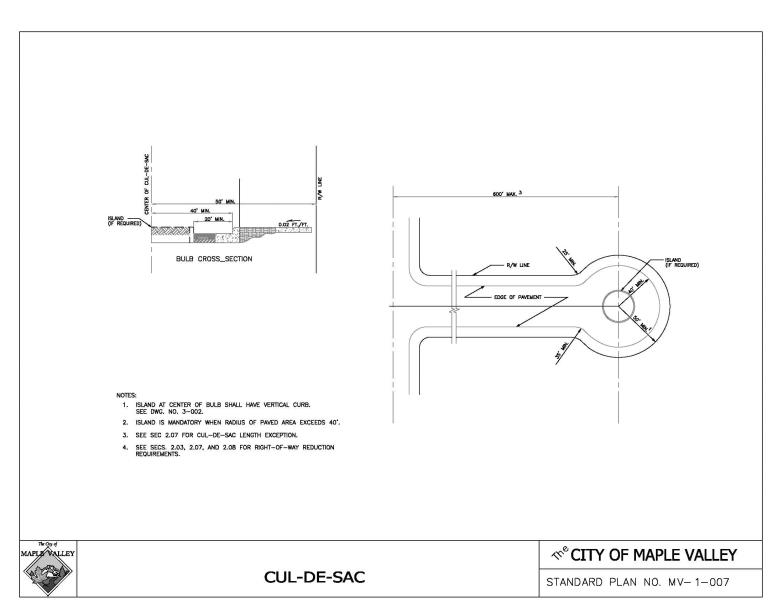
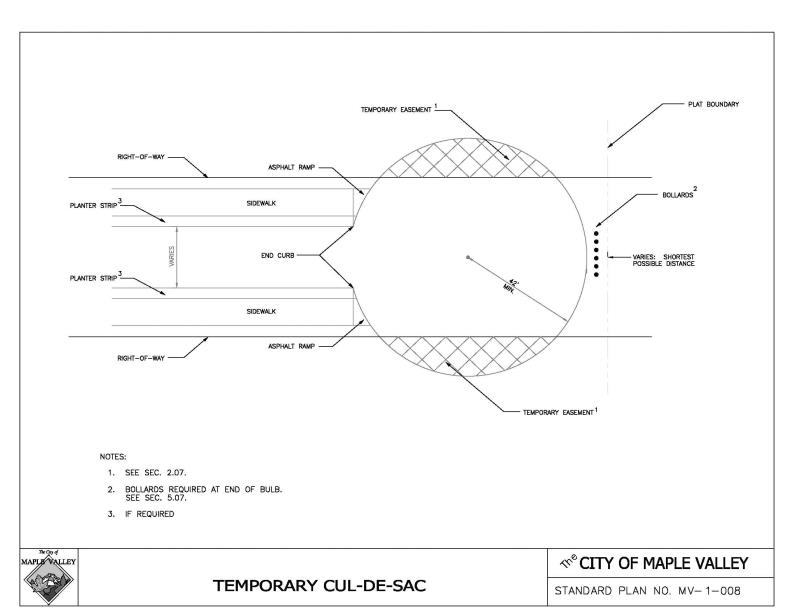
12.10.180 Cul-de-sacs and eyebrows.
See Drawings No. MV-1-007 through MV-1-009.
A. Whenever a cul-de-sac street serves more than six lots or extends more than 150 feet from centerline of intersecting street to farthest extent of surfaced traveled way, a widened “bulb” shall be constructed as follows:
1. Minimum right-of-way diameter across bulb section: 100 feet in a permanent cul-de-sac; 84 feet in a temporary cul-de-sac, with bulb area lying outside straight street right-of-way provided as temporary easement pending forward extension of the street. Right-of-way may be reduced, provided utilities and necessary drainage are accommodated on permanent easements within the development. See MVMC 12.10.270.
2. Minimum diameter of surfacing across bulb: 80 feet of paving in curb type road.
3. Cul-de-sac vegetated or bioretention islands are an optional feature for any cul-de-sac when bulb paved diameter is 80 feet or less and mandatory when bulb paved diameter exceeds 80 feet. Vegetated island shall have full-depth vertical curb with a minimum diameter of 20 feet. Bioretention island shall have extruded curb with curb cuts to allow stormwater to enter the facility and a minimum diameter of 15 feet. The paved traveled way around the circumference shall be a minimum of 20 feet. Vegetated and bioretention islands shall be landscaped with native and drought tolerant vegetation and maintained by the adjoining landowners or the homeowners’ association.
B. A permanent cul-de-sac shall not be longer than 600 feet measured from centerline of intersecting street to the center of the bulb section. Proposed exceptions to this rule will be considered by the Public Works Director based on pertinent traffic planning factors such as topography, sensitive areas and existing development.
C. The Public Works Director or City of Maple Valley may require an off-street walk or an emergency vehicle access to connect a cul-de-sac at its terminus with other streets, parks, schools, bus stops, or other pedestrian traffic generators.
D. The maximum length of a temporary cul-de-sac shall not exceed 150 feet.
E. The maximum cross slope in a bulb shall not exceed six percent.
F. Partial bulbs or eyebrows shall have a minimum paved radius and an island configuration as shown on Drawing No. MV-1-009. Island shall be offset two feet from edge of traveled way.
G. A landscape strip is not required for permanent cul-de-sacs, less than 150 feet measured from centerline of intersecting street to the center of the bulb and serving 15 or fewer dwelling units. (Ord. O-17-616 § 2 (Att. A); Ord. O-04-261 Exh. A, § 2.07).
12.10.190 Alleys and private access tracts.
A. An alley is considered a private access. Requirements of MVMC 12.10.140, neighborhood access streets, for horizontal curvature and stopping sight distance, apply.
1. Serves a maximum of 30 lots, with a maximum length of 400 feet, no dead ends or cul-de-sacs.
2. Minimum tract width 23 feet with a pavement surface of 20 feet (including thickened edge), and a minimum five-foot structure setback from alley. For structure setback requirements, alley configuration shall be designed to provide for safe turning access to properties.
3. Connecting streets to an alley shall be a 24-foot minimum paved width with vertical curb.
B. Private access tracts shall conform to MVMC 12.10.140 for neighborhood access roads and MVMC 12.10.160.
1. Serves a maximum of six parcels.
2. Minimum tract width of 24 feet with a maximum length of 150 feet, measured from centerline of intersecting street to furthest extent of paved tract.
3. Pavement width shall be a minimum of 20 feet. (Ord. O-17-616 § 2 (Att. A); Ord. O-04-261 Exh. A, § 2.08).
12.10.200 Intersections and low speed curves.
A. Intersections.
|
1. Angle of intersection (measured at 10 feet beyond road classification right-of-way) |
Minimum 85 degrees Maximum 95 degrees |
|
2. Minimum centerline radius |
55 feet |
|
3. Minimum curb radius |
|
|
a. Streets classified neighborhood collector or higher |
35 feet |
|
b. Neighborhood access street intersections where the highest classification involved is neighborhood access |
25 feet |
|
4. Minimum right-of-way line radius |
25 feet |
B. Spacing between adjacent intersecting streets, whether crossing or T-connecting, shall be as follows:
|
When highest classification involved is: |
Minimum centerline offset shall be: |
|
Principal Arterial |
1,000 feet |
|
Minor Arterial |
500 feet |
|
Boulevard Collector |
300 feet |
|
Neighborhood Collector |
150 feet |
|
Neighborhood Access |
125 feet |
|
Alley |
N/A |
C. On sloping approaches at an intersection, landings shall be provided with grade not to exceed one foot difference in elevation for a distance of 30 feet approaching an arterial or 20 feet approaching a residential or commercial street, measured from future right-of-way line (extended) of intersecting street as provided in MVMC 12.10.130 or 12.10.140. See Drawing No. MV-5-002.
D. Entering Sight Distance. See MVMC 12.10.130, 12.10.140 and 12.10.230 for design requirements. See Tables 2.1 or 2.2 (MVMC 12.10.150) for specific entering sight distance values based on required design speed.
E. Low Speed Curves, Applicable to Neighborhood Access and Lower Streets Only. See MVMC 12.10.140.
|
|
Up to 75º |
75º and Over |
|
1. Minimum centerline radius (2-lane) |
100 feet |
55 feet |
|
2. Minimum curb radius |
80 feet |
35 feet |
|
|
Up to 75º |
75º and Over |
|
3. Minimum right-of-way line radius |
70 feet |
25 feet |
(Ord. O-17-616 § 2 (Att. A); Ord. O-04-261 Exh. A, § 2.09).
12.10.210 Maximum grade and grade transitions.
A. Maximum grade as shown in MVMC 12.10.130 and 12.10.140 may be exceeded for short distances of 300 feet or less, upon showing that no practical alternative exists. Exceptions which exceed 12 percent will require verification by the Fire Marshal that additional fire protection requirements will be met.
B. Grade transitions shall be constructed as smooth vertical curves except in intersections where the difference in grade is one percent or less and upon approval of the Public Works Director. (Ord. O-17-616 § 2 (Att. A); Ord. O-04-261 Exh. A, § 2.10).
12.10.220 Stopping sight distance (SSD).
Applies to street classifications as shown in MVMC 12.10.130 and 12.10.140. See Tables 2.1 and 2.2 (MVMC 12.10.150) for specific SSD values based on required design speed.
A. Height of eye is three and one-half feet and height of object is two feet.
B. Minimum SSD for any downgrade averaging three percent or steeper as provided in MVMC 12.10.150, Tables 2.1 and 2.2, shall be increased by the values shown below for any downgrade averaging three percent or steeper (Source: AASHTO Policy on Geometric Design, Exhibit 3-2). Interpolate values for other design speeds and grades.
|
SSD ADJUSTMENT VALUES (FT) |
|||
|---|---|---|---|
|
|
DOWNGRADE |
||
|
DESIGN SPEED (MPH) |
3 Percent |
6 Percent |
9 Percent |
|
60 |
35 |
75 |
125 |
|
50 |
25 |
55 |
85 |
|
40 |
20 |
35 |
55 |
|
30 |
10 |
20 |
30 |
|
20 |
5 |
10 |
15 |
C. Sag vertical curves on neighborhood streets with stopping sight distance less than that called for in MVMC 12.10.140 may be approved by the Public Works Director if no practical design exists and if acceptable road lighting is provided throughout the curve and is maintained by a franchised utility.
D. Intersecting Stopping Sight Distance.
1. Stopping sight distances for the design speeds of proposed neighborhood collector streets and arterials must be met when intersecting arterials.
2. The minimum stopping sight distance on proposed intersection approaches for all other classifications of intersecting roadways shall be 125 feet. (Ord. O-17-616 § 2 (Att. A); Ord. O-04-261 Exh. A, § 2.11).
12.10.230 Entering sight distance (ESD).
Entering sight distance applies on driveways and on streets approaching intersections as set forth in MVMC 12.10.130 and 12.10.140. Entering sight distance criteria will not apply on neighborhood access streets. Specific ESD values for required design speeds are listed in MVMC 12.10.150, Tables 2.1 and 2.2.
A. Entering vehicle eye height is three and one-half feet, measured from 10 feet back from edge of traveled way. Approaching vehicle height is four and one-quarter feet.
B. Requirements in MVMC 12.10.150, Tables 2.1 and 2.2, apply to an intersection or driveway approach to a typical road under average conditions. In difficult topography, the Public Works Director may authorize a reduction in the ESD based on factors mitigating the hazard. Such factors may include an anticipated posted or average running speed less than the design speed or the provision of acceleration lanes and/or a median space allowing an intermediate stop by an approaching vehicle making a left turn.
C. Where a significant number of trucks will be using the approach road, the Public Works Director may increase the entering sight distance requirements by up to 30 percent for single-unit trucks and 70 percent for semi-trailer combinations. (Ord. O-17-616 § 2 (Att. A); Ord. O-04-261 Exh. A, § 2.12).
12.10.240 One-way streets.
Local access streets, including loops, may be designated one-way upon a finding by the Public Works Director that topography, use of low impact development facilities, or other site features make two-way traffic impractical. (Ord. O-17-616 § 2 (Att. A); Ord. O-04-261 Exh. A, § 2.13).
12.10.250 Bus zones.
During the design of arterials and neighborhood collectors, the designer shall contact Metro Service Planning and the Tahoma School District to determine bus zone (stop) locations and other bus operation needs. The road project shall provide wheelchair accessible landing pads at designated bus zones as per MVMC 12.10.320 and where required shall include shelter pads. Pedestrian and handicapped access improvements within the right-of-way to and from the bus loading zone or turn-out from nearby businesses or residences shall also be provided as part of the road improvement. Surfacing requirements may also be affected, particularly on shoulders. See MVMC 12.10.410(B). Metro’s publication, “Metro Transportation Facility Design Guidelines,” is applicable. (Ord. O-17-616 § 2 (Att. A); Ord. O-04-261 Exh. A, § 2.14).
12.10.260 Intersections with State or federal highways.
In the event that the City has jurisdiction on a development that requires the construction or improvement of a commercial/industrial driveway or any classification of street that intersects a State or federal highway, minimum intersection spacing, entering sight distance and landing requirements in accordance with these standards shall be satisfied in addition to the requirements of all other applicable permits. In the instance State or federal standards exceed these standards, State or federal standards shall govern. (Ord. O-17-616 § 2 (Att. A); Ord. O-04-261 Exh. A, § 2.15).
12.10.270 Slope, wall, and drainage easements and right-of-way reduction.
A. Easements. Either the functional classification or particular design features of a road may necessitate slope, sight distance, wall or drainage easements beyond the right-of-way line. Such easements may be required by the Public Works Director or City of Maple Valley in conjunction with dedication or acquisition of right-of-way.
B. Right-of-Way Reduction on Nonarterial Streets. Where it is desired by the City to reduce right-of-way to a minimum width, the right-of-way, plus easement, shall allow for construction and maintenance of the following as appropriate: sidewalks, planter strips, drainage facilities, sign placement, and also allow sidewalk widening around mailbox locations. On neighborhood collectors, installation of fixed objects, other than required above ground utility structures, greater than four inches in diameter within four feet of back of sidewalk shall not be permitted. (Ord. O-17-616 § 2 (Att. A); Ord. O-04-261 Exh. A, § 2.16).
12.10.280 Access and circulation requirements.
In order to provide a second access to a residential subdivision, short subdivision, binding site plan or planned unit development, no neighborhood collector or neighborhood access street shall serve more than 100 lots or dwelling units or have an ADT of greater than 1,000 vehicles per day unless the street is connected in at least two locations with another street that functions at a level consistent with MVMC 12.10.130 and 12.10.140. In addition, neighborhood access streets shall also be extended or connected to the City street system in conformance with the Street Connectivity Evaluation Criteria (See Exhibit A of Resolution R-99-98, on file in the City Clerk’s office).
A. The second access requirement may be satisfied through use of connecting a new street to an existing street in an adjacent neighborhood if:
1. No other practical alternative exists; or
2. Existing street was previously stubbed indicating intent for future access; or
3. An easement has been recorded specifically for said purpose.
B. The second access requirement may not be satisfied through use of an existing roadway network in the existing adjacent neighborhood if:
1. A more practical alternative exists; or
2. Existing streets do not meet the minimum roadway width detailed in MVMC 12.10.140.
These provisions are not intended to preclude the State statute on land locking. (Ord. O-17-616 § 2 (Att. A); Ord. O-04-261 Exh. A, § 2.17).
12.10.290 Traffic signals and roundabouts.
A. Roundabouts may be considered at intersections within the City of Maple Valley. Proposed roundabouts shall be evaluated consistent with WSDOT Design Manual Sections 910.08 and 915.01.
B. Preparation of traffic signal plans and specifications and other traffic control devices shall be consistent with the WSDOT standard specifications and procedures for maintenance and operations. All designs must be prepared by a licensed engineer, registered in the State of Washington, with experience in preparation of traffic signal plans/specifications. A pre-design meeting must be scheduled by the applicant to coordinate with the City on general requirements and identify the parameters of the design. “Boiler plate” specifications for traffic signals will be provided by the City on disc for the applicant to prepare final specifications for approval by the Director of Public Works.
1. The permittee is responsible for securing any State and local permits needed for traffic signalization and regulatory signing and marking.
2. All signals shall be equipped with preemption that is compatible with the equipment approved by Maple Valley Fire and Life Safety. New traffic signal installations shall include a minimum of one spare conduit run (two-inch minimum) for any arterial crossing.
3. Warrants for traffic signals shall be consistent with the practices set forth in the MUTCD. The Director of Public Works shall determine consistency with these practices based on submitted information by the applicant when determining if a traffic signal is warranted and consistent with City planning.
4. Traffic signal interconnect to nearby affected signals may be required for any new traffic signal installation to promote progression of traffic and improved efficiency of the travel stream. (Ord. O-17-616 § 2 (Att. A); Ord. O-04-261 Exh. A, § 2.18).
12.10.300 Corridor studies.
Any standard listed in this chapter may be superseded by adoption of a corridor study by the City of Maple Valley City Council on specific arterial or collector roadways. (Ord. O-17-616 § 2 (Att. A); Ord. O-04-261 Exh. A, § 2.19).
Article III. Driveways, Walks and Trails
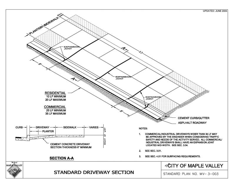
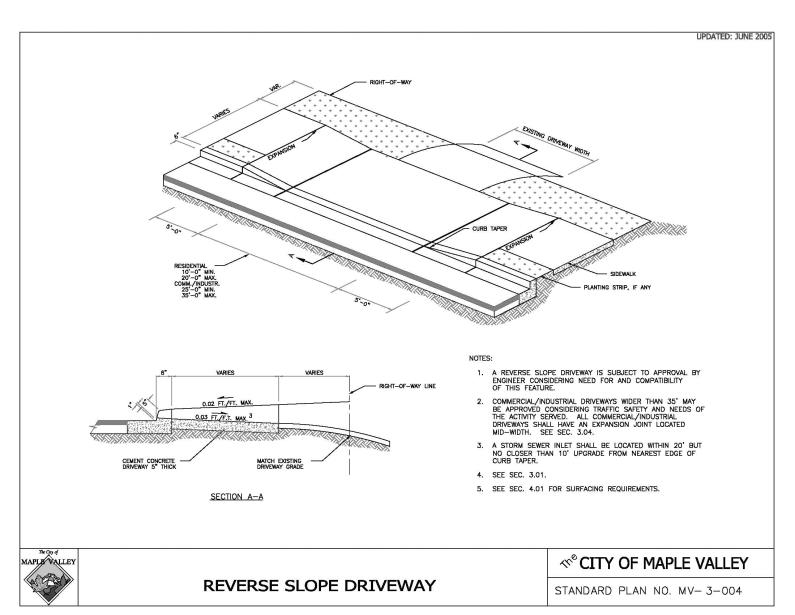
12.10.310 Driveways.
A. Dimensions, slope, and detail shall be as indicated in Drawings No. MV-3-001, MV-3-003, MV-3-004 and MV-3-005, as further specified in the following subsections. See MVMC 12.10.230 for entering sight distance requirements.
B. Conditions for Approval of New Driveways.
1. Driveways directly giving access onto arterials may be denied if alternate access is available.
2. All abandoned driveway areas on the same frontage shall be removed and the curbing and sidewalk shall be properly restored.
3. Maintenance of driveway approaches shall be the responsibility of the owner whose property they serve.
4. For a commercial establishment on a shoulder and ditch type road, where development of adjoining lands and highway traffic assume urban characteristics as determined by the City, the frontage shall be finished with curb, gutter, and sidewalk, with pipe drainage, all in accordance with these standards.
5. For driveways crossing an open ditch section, culverts shall be adequately sized to carry anticipated stormwater flows and in no case be less than 12 inches in diameter. The property owner making the installation shall be responsible for determining proper pipe size. The City may require the owner to verify the adequacy of pipe size.
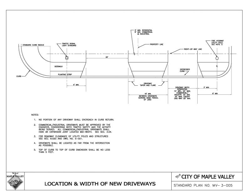
C. Location and Width of New Driveways. Refer to Drawing No. MV-3-005.
1. A residential driveway shall typically serve only one parcel. A driveway serving more than one parcel shall be classed as a commercial driveway or a private access tract, except as provided in subsections (C)(2)(a) and (b) of this section.
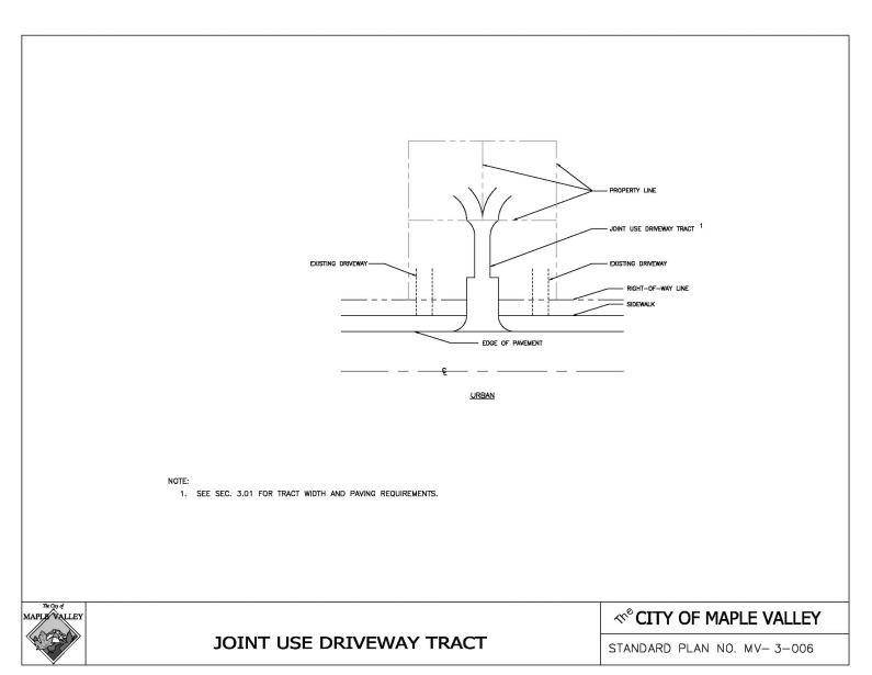
2. No portion of driveway width shall be allowed within five feet of side property lines in residential areas or nine feet in commercial areas except as follows:
a. A joint use driveway tract may be used to serve two parcels. Minimum tract width shall be 23 feet with a 20-foot paved surface, cross slope in one direction and curb on one side unless sheet flow dispersion is being implemented. Radius returns on paved apron shall have 10-foot radii. Joint use driveway shall have a maximum length of 150 feet. A two-track driveway design and use of permeable pavement will also be evaluated.
b. Driveways may utilize full width of narrow “pipe-stem” parcels or easements if approved by the City.
c. On cul-de-sac bulbs as necessary for proposed residential access.
3. Grade transitions, excluding the tie to the roadway, shall be constructed as smooth vertical curves. Ties to the roadway shall be constructed as shown in Drawings No. MV-3-003 and MV-3-004. The maximum change in driveway grade, within the right-of-way, shall be eight percent within any 10 feet of distance on a crest and 12 percent within any 10 feet of distance in a sag vertical curve. Driveway shall be graded to match into possible future widened road section without encroachment into graded shoulder or sidewalk. The design engineer for proposed developments shall consider the access driveway profile when designing the serving road to ensure that required grade transitions can be complied with considering building setback and lot terrain conditions.
4. Senior high schools in Public zones may reduce the minimum required driveway width to 20 feet.
D. Owners of property adjacent to public right-of-way may maintain existing driveways unless the Public Works Director determines that a safety hazard exists.
E. For commercial or industrial driveways with heavy traffic volumes or significant numbers of trucks, the City may require construction of the access as a road intersection. This requirement will be based on traffic engineering analysis submitted by the applicant that considers, among other factors, intersection spacing, sight distance and traffic volumes.
F. Driveways will not be permitted where they are determined by the City of Maple Valley to create a safety hazard or impede the traffic flow on the intersecting roadway. (Ord. O-17-616 § 2 (Att. A); Ord. O-14-564 § 1 (Exh. A); Ord. O-04-261 Exh. A, § 3.01).
12.10.320 Concrete sidewalks.
Concrete sidewalks:
A. Shall be constructed on both sides of the street and around the radius of cul-de-sac streets.
B. Shall be constructed:
1. At least eight feet wide, including landscaping, when a combined landscape and sidewalk area is allowed.
2. At least five feet wide on boulevard collector, neighborhood collector and neighborhood access streets, except where approved as a variance.
3. At least six feet wide, provided along all minor arterial streets and business access streets.
4. At least eight feet wide:
a. Provided along all principal arterials.
b. Within the curb radius returns of all arterial intersections where curb ramps are required.
c. Within designated bus zones to provide a landing area for wheelchair access to transit services.
5. The Public Works Director shall require a sidewalk of greater width when additional width is warranted by expected pedestrian traffic volumes.
6. With Portland cement concrete surfacing, or approved equal that provides equivalent maintenance cost, surface texture, and functionality as provided in MVMC 12.10.330 and 12.10.410. See MVMC 12.10.340 and Drawing No. MV-3-001 for joint details.
C. Meandering Sidewalk Option. A meandering sidewalk may be provided in lieu of standard sidewalk above with the approval of the Public Works Director.
1. Shall be a minimum of six feet wide.
2. Easements outside the required right-of-way shall be required for portions of walkway beyond the right-of-way.
3. Landscape areas associated with meandering sidewalks may be included in credit towards landscape requirements for development. (Ord. O-17-616 § 2 (Att. A); Ord. O-04-261 Exh. A, § 3.02).
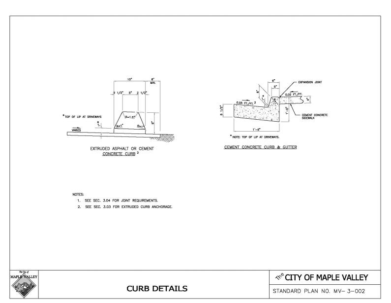
12.10.330 Curbs, gutters and sidewalks.
A. Subgrade compaction for curbs, gutters, and sidewalks shall meet a minimum 90 percent of maximum density.
B. Concrete for curbs, gutters, and sidewalks shall be Class 3000, furnished and placed in accordance with WSDOT/APWA Standard Specifications, Sections 6-02, 8-04, and 8-14. Cold weather precautions as set forth in WSDOT/APWA Standard Specifications, Sections 5-05.3(14) and 6-02.3(6)(A), shall apply.
C. Extruded cement concrete curb, when permitted, shall be anchored to existing pavement by either steel tie bars or adhesive in conformance with WSDOT/APWA Standard Specifications, Section 8-04.
D. Extruded asphalt curbs shall be anchored by means of a tack coat of asphalt in accordance with WSDOT/APWA Standard Specifications, Section 8-04. (Ord. O-17-616 § 2 (Att. A); Ord. O-04-261 Exh. A, § 3.03).
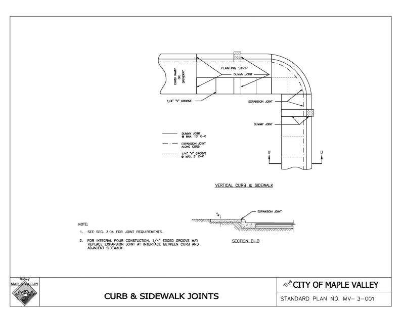
12.10.340 Expansion and dummy joints.
See Drawing No. MV-3-001.
A. An expansion joint consisting of three-eighths inch or one-quarter inch by full depth of premolded joint material shall be placed around fire hydrants, poles, posts, and utility castings and along walls or structures in paved areas. Joint material shall conform to the requirements of ASTM D994 (AASHTO M33).
B. A dummy joint consisting of three-eighths inch or one-quarter inch by two inches of premolded joint material shall be placed in curbs and sidewalks at 10-foot intervals and at sides of drainage inlets. When curbs and/or sidewalks are placed by slip forming, a premolded strip up to one-half inch thick and up to full depth may be used.
C. Dummy joints in sidewalk shall be located so as to match the joints in the curb whether sidewalk is adjacent to curb or separated by landscape strip.
D. Tool marks consisting of one-quarter inch V-grooves shall be made in sidewalk at five-foot intervals, intermediate to the dummy joints.
E. As alternative to expansion joints around structures, reinforcing bars may be embedded in concrete on four sides of structures. (Ord. O-17-616 § 2 (Att. A); Ord. O-04-261 Exh. A, § 3.04).
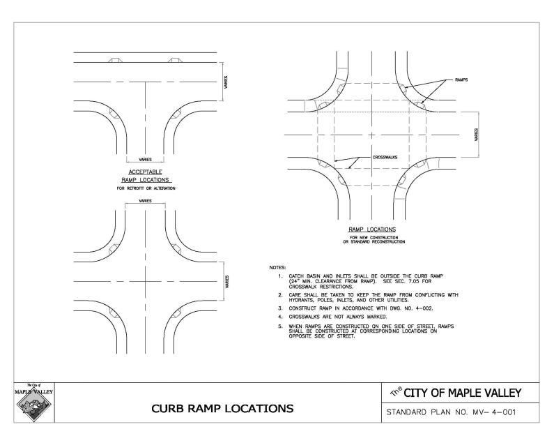
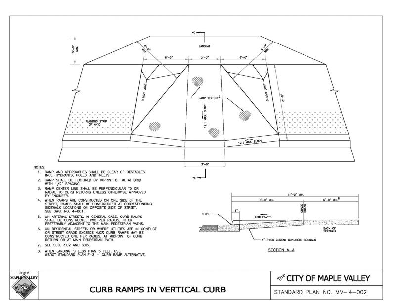
12.10.350 Curb ramps.
On all streets with vertical curb sections, curb ramps shall be constructed to facilitate passage of handicapped persons through curb and sidewalk at street intersections and other crosswalk locations. See Drawing No. MV-4-002. Where a ramp is constructed on one side of the street, a ramp shall also be provided on the opposite side of the street. Curb ramps shall be positioned so that a ramp opening is situated within the marked crosswalk or crossing area if unmarked. (Ord. O-17-616 § 2 (Att. A); Ord. O-04-261 Exh. A, § 3.05).
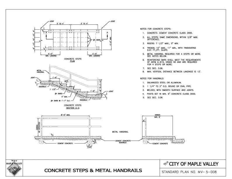
12.10.360 Concrete steps, metal handrail and handicapped access ramps.
A. Steps shall only be used where acceptable alternative access is available for handicapped access and there is a need for a separate stairway. Where used, concrete steps shall be constructed in accordance with Drawing No. MV-5-008 or other design acceptable to the Public Works Director consistent with the WSDOT/APWA Standard Specifications. Handrails, whether for steps or other applications, shall be provided consistent with Drawing No. MV-5-008 and the WSDOT/APWA Standard Specifications.
B. Ramps used to provide handicapped access shall have a maximum slope of 12:1 with a maximum rise of 30 inches between landings. Landings shall have a minimum length of five feet and should be of sufficient width to allow wheelchairs to pass, generally five feet minimum width for two-way traffic. (Ord. O-17-616 § 2 (Att. A); Ord. O-04-261 Exh. A, § 3.06).
12.10.370 Separated walkways, bikeways and trails.
Separated pedestrian, bicycle and equestrian trails shall be provided where designated in community and functional plans or where required by the Public Works Director because of anticipated significant public usage. Where separate walkways, bikeways, or equestrian trails intersect with motorized traffic, sight distance, marking and signalization (if warranted) shall be as provided in MUTCD. Facilities shall be designed as follows:
A. Walkways designed primarily for pedestrians shall be in a 15-foot tract with an eight-foot asphalt surface or equivalent material, such as permeable pavement.
B. Neighborhood pathways are soft surface facilities designed for pedestrians and equestrians. Such pathways shall be a minimum eight feet wide with at least one and one-half foot clearance to obstructions on both sides and 10 feet vertical clearance. Pathways shall be designed and located so as to avoid drainage and erosion problems. Pathways shall be constructed of two and one-half inches of crushed surfacing top course, permeable pavement, or wood chips over cleared native material as approved by the City of Maple Valley.
C. Multipurpose trails are typically designated for bicycle and pedestrian use and in general follow a right-of-way independent from any road. Multipurpose trails shall be designed to bicycle path standards as described in MVMC 12.10.390. (Ord. O-17-616 § 2 (Att. A); Ord. O-04-261 Exh. A, § 3.07).
12.10.380 School access.
School access required as part of development approval shall be provided by an asphalt walkway, concrete sidewalk or equivalent material such as permeable pavement unless another alternative is available and approved by the Public Works Director through a road variance request. (Ord. O-17-616 § 2 (Att. A); Ord. O-04-261 Exh. A, § 3.08).
12.10.390 Bikeways.
A. Bikeways are generally shared with other transportation modes, although they may be provided exclusively for bicycle use. Bikeways are categorized below based on degree of separation from motor vehicles and other transportation modes. This classification does not denote preference of one type over another. Bikeways are categorized and characterized in standard drawings MV-1-001 through MV-1-003 as follows:
1. Bike path (Class I): A separate paved or permeable pavement multipurpose trail for the principal use of bicycles and other nonmotorized modes. Bike paths are 12 feet wide and provide 10 feet vertical clearance.
2. Bike lane (Class II): A portion of the road that is designated by pavement striping for exclusive bicycle use. Bicycle lanes may be signed as part of a directional route system. Bicycle lanes are five feet wide on a curbed road. Required on all arterial roadways.
3. Wide curb lane (Class III): A road that provides a widened paved outer curb lane to accommodate bicycles in the same lane as motor vehicles. Lane width shall be increased at least three feet. Required on boulevard collectors.
4. Shared roadway: All roads not categorized above where bicycles share the roadway with motor vehicles.
B. A bikeway shall be provided:
1. Wherever called for in the Nonmotorized Transportation Plan, Transportation Plan, Comprehensive Plan, community plan, Capital Improvement Program or Transportation Needs Report.
2. When substantial bike usage is expected which would benefit from construction of a bicycle facility.
C. Striping and signing shall be implemented as follows:
1. Pavement markings shall be used on bike lanes and paths according to MUTCD.
2. The design of all signalized intersections shall consider bicycle usage and the need for bicyclists to actuate the signal.
D. The planning and design of bikeways in any category shall be in accordance with Section 1020 of the WSDOT Design Manual and the AASHTO Guide for the Development of Bicycle Facilities, current edition. (Ord. O-17-616 § 2 (Att. A); Ord. O-04-261 Exh. A, § 3.09).
12.10.400 Equestrian facilities.
A separate equestrian trail shall be constructed with an 18 percent maximum grade, 10-foot vertical clearance and a five-foot-wide pathway zone. The trail shall be constructed of native soil or, where drainage or erosion problems are present, a minimum of two and one-half inches of crushed surfacing top course on graded and compacted native soil. Native soil which is not free-draining shall be removed and replaced with free-draining soil as necessary to provide a maintainable and well-drained subgrade. Additional crushed surfacing, cinders or other stabilizing materials shall be required if heavy usage is anticipated or if there is any evidence of instability in the subgrade, including free water, swamp conditions, fine-grained or organic soils, slides or uneven trails. (Ord. O-17-616 § 2 (Att. A); Ord. O-04-261 Exh. A, § 3.10).
Article IV. Surfacing
12.10.410 Residential streets, pedestrian and bike.
The minimum paved section, with alternative combinations of materials, for residential streets, sidewalks and bikeways shall be as indicated below. These sections are acceptable only on visually good, well-drained, stable compacted subgrade. Any proposed exception to these materials will be subject to soils strength testing and traffic loading analysis and subject to review and approval by the Public Works Director as outlined in MVMC 12.10.420. All expenses for determining revised materials shall be borne by the developer.
|
TYPE OF FACILITIES |
ASPHALT CONCRETE |
ASPHALT TREATED BASE |
CRUSHED SURF. TOP COURSE |
PORTLAND CEMENT CONCRETE |
CRUSHED SURF. BASE COURSE |
|---|---|---|---|---|---|
|
A. NEIGHBORHOOD STREETS |
|||||
|
Boulevard Collector and Business Access |
3" |
4" |
|
|
1 1/2" |
|
Neighborhood Collector and Lower |
2" |
4" |
|
|
1 1/2" |
|
Bike Path (when separated) |
2" |
|
1 1/2" |
|
2 1/2" |
|
B. SIDEWALKS |
|||||
|
ALL |
|
|
|
Class 3000, 4" or equivalent material such as permeable pavement |
1 1/2" |
|
C. WALKWAYS/BIKEWAYS |
|||||
|
ALL |
2" |
|
1 1/2" |
|
2 1/2" |
|
When a bikeway is incorporated into a road section, the required section shall govern. Subgrade compaction for bikeways and paved walkways shall meet a minimum of 90 percent maximum density. |
|||||
D. Driveway aprons in the public right-of-way or public easement shall be paved with Portland cement concrete Class 4000 or equivalent material such as permeable pavement. See Drawings No. MV-3-003 and MV-3-004.
E. Street Widening/Adding Traveled Way to Existing Roads.
1. When an existing asphalt paved street is to be widened, the edge of pavement shall be saw cut to provide a clean, vertical edge for joining to the new asphalt. After placement of the new asphalt section, the joint shall be sealed and the street overlaid one inch, plus a pre-level course, full width throughout the widened area. The requirement for overlay may be waived by the Public Works Director or City of Maple Valley based on the condition of existing pavement and the extent of required changes to channelization.
2. Any widening of an existing roadway, either to add traveled way or paved shoulder shall have the same surfacing material and section as the existing roadway or equivalent material such as permeable pavement. (Ord. O-17-616 § 2 (Att. A); Ord. O-04-261 Exh. A, § 4.01).
12.10.420 Requirements for residential streets on poor subgrade.
The minimum material thicknesses indicated in MVMC 12.10.410 are not acceptable if there is any evidence of instability in the subgrade. This includes free water, swamp conditions, fine-grained or organic soil, slides or uneven settlement. If there are any of these characteristics, the soil shall be sampled and tested sufficiently to establish a pavement design that will support the proposed construction. Any deficiencies, including an R value of less than 55 or a CBR of less than 20, shall be fully considered in the design. Remedial measures may include, but are not limited to, a stronger paved section, a strengthening of subgrade by adding or substituting fractured aggregate, asphalt treated base, installing a geotextile, more extensive drainage or a combination of such measures. Both the soils test report and the resulting pavement design will be subject to review and approval by the Public Works Director. (Ord. O-17-616 § 2 (Att. A); Ord. O-04-261 Exh. A, § 4.02).
12.10.430 Arterial streets.
Any pavement for arterials and commercial access streets shall be designed using currently accepted methodology that considers the load-bearing capacity of the soils and the traffic-carrying requirements of the roadway. Plans shall be accompanied by a pavement thickness design based on soil strength parameters reflecting actual field tests and traffic loading analyses. The analysis shall include the traffic volume and axle loading, the type and thickness of roadway materials and the recommended method of placement. Pavement sections shall not be less than those required for neighborhood collectors. (Ord. O-17-616 § 2 (Att. A); Ord. O-04-261 Exh. A, § 4.03).
12.10.440 Materials and lay-down procedures.
Materials and lay-down procedures shall be in accordance with WSDOT/APWA Standard Specifications and the following requirements:
A. During surfacing activities, utility covers in roadway shall be adjusted in accordance with MVMC 12.10.720.
B. ATB may be used over isolated areas of unstable subgrade, providing the final lift of asphalt shall not be placed for a minimum of six months to allow time for the observation and repair of failures in the subgrade and ATB.
C. When constructing new streets associated with land development, the developer shall not complete the final lift of pavement (minimum of one and one-half inches) until:
1. Eighty percent of the units being developed along the new street have been accepted as complete by the City of Maple Valley; or
2. The Public Works Director deems it to be in the best interest of the City of Maple Valley.
D. Asphalt pavers shall be self-contained, power-propelled units. Truck-mounted type pavers are not considered self-propelled. Truck-mounted pavers shall only be used for paving of irregularly shaped or minor areas as approved by the Public Works Director, or as follows:
1. Pavement widths less than eight feet; and
2. Pavement lengths less than 150 feet. (Ord. O-17-616 § 2 (Att. A); Ord. O-04-261 Exh. A, § 4.04).
12.10.450 Pavement markings, markers, and pavement tapers.
Pavement markings, markers or striping shall be used to delineate channelization, lane endings, crosswalks and longitudinal lines to control or guide traffic. All pavement markings, markers, and pavement tapers shall be consistent with the MUTCD, WSDOT Design Manual and these standards. Channelization plans or crosswalk locations shall be approved by the Traffic Engineer.
Channelization shall be required when through traffic is diverted around a lane or obstacle; and when connecting full width streets with different cross sections; and when extending an existing street with a new cross section different than the existing one. The channelization shall provide tapers equal in length to the posted speed limit times the distance in feet of diversion from the road centerline or the original alignment of travel, or the offset distance, as applicable. Channelization shall also be required to redirect traffic back to their original alignment.
Left turn channelization shall include a minimum of 150 feet of full width lane to include storage and a reverse curve 90 feet in length for posted speeds up to 45 miles per hour. The reverse curve shall be 120 feet in length for posted speeds greater than 45 miles per hour. The reverse curve may be included within the taper distance. A deceleration taper as shown in the WSDOT/APWA Standard Plans may be used in place of a reverse curve. Standard left turn lanes shall be 12 feet wide. Type 2L arrows shall be installed in the lane 25 feet and 100 feet behind the stop bar, crosswalk or stopping area. Additional storage may be required for long vehicles or anticipated left turn queues longer than the minimum storage.
Centerline for channelization shall consist of two four-inch yellow lines with a four-inch separation. Type 2D lane markers shall be installed at 40-foot centers between the lines. Holding lines for additional lanes shall be eight-inch white lines with Type 2E lane marker on the inside of the lane at 20-foot centers. Edgelines for tapering through traffic back to the original alignment shall consist of four-inch white lines.
Pavement markings for channelization shall be reflectorized hot or cold applied plastic. Extruded or sprayed markings shall be dressed with glass beads for initial reflectance. All materials shall have beads throughout the material to maintain reflectance while the material wears.
Where pavement widening less than 300 feet in length is abruptly ended and edge lines do not direct traffic to through lanes, Type 2E lane markers shall be installed at 10-foot centers near the end of the paved area at a 10:1 taper.
Crosswalks shall be installed at all intersections controlled by traffic signals and other areas approved by the Traffic Engineer. Crosswalks shall consist of sets of longitudinal lines eight inches wide by 10 feet and with eight-inch separation. A set of these lines shall be installed between each lane, between the wheel tracks in each lane and at the pavement edges.
All pavement markings shall be laid out with spray paint and approved by the Traffic Engineer before they are installed. Approval may require a three-working-day advance notice to have field layout approved by the Traffic Engineer or to make arrangements to meet the Traffic Engineer on site during the installation. (Ord. O-17-616 § 2 (Att. A); Ord. O-04-261 Exh. A, § 4.05).
Article V. Roadside Features
12.10.460 Rock facings.
A. Rock facings may be used for the protection of cut or fill embankments up to a maximum height of eight feet above the keyway in stable soil conditions which will result in no significant foundation settlement or outward thrust upon the walls. See Drawings No. MV-5-004 through MV-5-007. For heights over eight feet above the keyway or when soil is unstable, a structural wall of acceptable design shall be used. As an exception, rock-facing heights may exceed eight feet to a limited extent based on favorable soils analyses and a design by a geotechnical engineer or other professional engineer qualified in rock wall design, subject to approval by the Public Works Director. Terracing of rockeries is subject to approval by the Public Works Director.
B. Materials.
1. Size categories shall include:
a. Two-man rocks (200 to 700 pounds), 18 inches to 28 inches in average dimension;
b. Three-man rocks (701 to 2,000 pounds), 28 inches to 36 inches in average dimension; and
c. Four-man rocks (2,001 to 4,000 pounds), 36 inches to 48 inches in average dimension.
Four-man rocks shall be used for bottom course rock in all rock facings over six feet in height.
2. The rock material shall be as nearly rectangular as possible. No stone shall be used which does not extend through the wall. The quarried trap rock shall be hard, sound, durable and free from weathered portions, seams, cracks and other defects. The rock density shall be a minimum of 160 pounds per cubic foot, measured according to WSDOT Test Method 107 (Bulk Specific Gravity – S.S.D. Basis). Additionally, rock subjected to the U.S. Army Corps of Engineers Test Method CRD-C-148 (“Method of Testing Stone for Expansive Breakdown on Soaking in Ethylene Glycol”) must have less than 15 percent breakdown.
C. Keyway. A keyway consisting of a shallow trench of minimum 12-inch depth shall be constructed the full rockery length, and slightly inclined towards the face being protected. It shall be excavated the full rockery width including the rock filter layer. The keyway subgrade shall be firm and acceptable to the Engineer. See Drawing No. MV-5-004.
D. Underdrains.
1. A minimum six-inch diameter perforated or slotted drainpipe shall be placed in a shallow excavated trench located along the inside edge of the keyway. The pipe shall be bedded on and surrounded by “Gravel Backfill for Drains” (WSDOT/APWA 9-03.12(4)) to a minimum height of 18 inches above bottom of pipe. A filter fabric shall surround the gravel backfill and shall have a minimum one-foot overlap along the top surface of the gravel. This requirement for fabric may be waived by the Engineer if shown that soils and water conditions make it unnecessary. See Drawings No. MV-5-004 through MV-5-006.
2. The perforated pipe shall be connected to the storm drain system or to an acceptable outfall.
E. Rock Selection and Placement. Rock selection and placement shall be such that there will be minimum voids and, in the exposed face, no open voids over six inches across in any direction. The final course shall have a continuous appearance and be placed to minimize erosion of the backfill material. The larger rocks shall be placed at the base of the facing so that it will be stable and have a stable appearance. The rocks shall be placed in a manner such that the longitudinal axis of the rock shall be at right angles to the face. The rocks shall have all inclined faces sloping to the back of the facing. Each course of rocks shall be seated as tightly and evenly as possible on the course beneath. The rocks shall be placed so that there are no continuous joint planes either horizontally or vertically. After setting each course of rock, all voids between the rocks shall be chinked on the back with quarry rock to eliminate any void sufficient to pass a two-inch square probe. See Drawings No. MV-5-004 through MV-5-006.
F. Rock Filter Layers. The rock filter layer shall consist of quarry spalls with a maximum size of four inches and a minimum size of two inches. This material shall be placed to a 12-inch minimum thickness between the entire facing and the cut or fill material. The backfill material shall be placed in lifts to an elevation approximately six inches below the top of each course of rocks as they are placed, until the uppermost course is placed. Any backfill material on the bearing surface of one rock course shall be removed before setting the next course.
G. Fill Rockery Facing Supporting Roadway Embankment. Embankment behind rockeries exceeding four feet in height above the keyway shall be reinforced with a geosynthetic fabric or geogrid specifically manufactured for soil reinforcement, designed on a project specific basis by a qualified engineer. See Drawing No. MV-5-007.
H. Sidewalks above Rockery Facings. When a sidewalk is to be built over a rock facing, the top of the facing shall be sealed and leveled with a cap constructed of cement concrete Class 3000 in accordance with the applicable provisions of Section 6-02 of the WSDOT/APWA Standard Specifications, but with reduced water content resulting in slump of not over two inches. See Drawing No. MV-5-006.
I. Fences or Handrails. A wood fence or metal handrail shall be installed when rockery is three feet or greater in height. See Drawings No. MV-5-004 through MV-5-006 and MV-5-008.
J. Sidewalks Adjacent to Rockery Facings. When a sidewalk is built adjacent to a rock facing, the facing shall be set back three feet for wall heights over four feet. (Ord. O-17-616 § 2 (Att. A); Ord. O-04-261 Exh. A, § 5.01).
12.10.470 Side slopes.
A. Side slopes shall generally be constructed no steeper than 2:1 on both fill slopes and cut slopes. Steeper slopes may be approved by the Engineer upon showing that the steeper slopes, based on soil analyses, will be stable. Side slopes on projects funded by federal grants shall be constructed in conformance with local agency guidelines.
B. Side slopes shall be stabilized by grass sod or seeding or by other planting or surfacing materials acceptable to the Engineer. (Ord. O-17-616 § 2 (Att. A); Ord. O-04-261 Exh. A, § 5.02).
12.10.480 Street trees and landscaping.
A. Street trees and landscaping should be incorporated into the design of road improvements for all classifications of roads. Such landscaping in the right-of-way shall be coordinated with off-street landscaping required on developer’s property under the provisions of Maple Valley requirements.
B. Landscape strips are required along all roads except neighborhood access. The design of landscape strips must be approved by the Public Works Director and must include a landscaping plan in which plant maintenance, utilities and traffic safety requirements are discussed.
C. Existing trees and landscaping shall be preserved where not in conflict with utilities and public health and safety and placement of new trees shall be compatible with other features of the environment. In particular, maximum heights and spacing shall not conflict unduly with overhead utilities, or root development with underground utilities. If street trees are planted, they shall conform to Exhibit A within the City’s street tree list.
D. New trees may be approved for street planting on public rights-of-way in the City of Maple Valley from the street tree list maintained by the Department of Community Development or alternate species may be approved by the Director of Community Development. Refer to the street tree list for spacing requirements. (Ord. O-20-704 § 1; Ord. O-17-616 § 2 (Att. A); Ord. O-04-261 Exh. A, § 5.03).
12.10.490 Mailboxes.
A. The responsibilities for location and installation of mailboxes in connection with the construction or reconstruction of City roads are as follows:
1. The Public Works Director or his representative will:
a. Require road improvement plans, whether for construction by the Department of Public Works or by a private builder, to show clearly the designated location or relocation of mailboxes, whether single or in clusters.
b. Require with this information any necessary widening or reconfiguration of sidewalks with suitable knock-outs or open strips for mailbox posts or pedestals.
c. Require these plans to bear a statement on the first sheet that mailbox locations as shown on these plans have been coordinated with the serving post office at Maple Valley, Washington. This will be a prerequisite to plan approval.
d. Require construction of mailbox locations in accordance with these plans, through usual inspection and enforcement procedures.
2. Builders or their contractors shall:
a. Where there is an existing mailbox, and no plans to replace it with a neighborhood delivery and collection box unit (NDCBU): When it becomes necessary to remove or otherwise disturb existing mailboxes within the limits of any project, install the boxes temporarily in such a position that their function will not be impaired. After construction work has been completed, reinstall boxes at original locations or at new approved locations as indicated on the plans or as directed by the Public Works Director. Only use existing posts or materials except that any damage caused by the builder or his contractor is to be repaired at the expense of the builder.
b. Where there are existing NDCBUs or plans to install NDCBUs: Call Maple Valley Postmaster or designated serving post office to approve the new or proposed location of the NDCBUs.
B. Installation methods are as follows: NDCBUs will be purchased and installed to specifications of U.S. Postmaster generally in accordance with Drawing No. MV-5-010. (Ord. O-17-616 § 2 (Att. A); Ord. O-04-261 Exh. A, § 5.04).
12.10.500 Street illumination.
Street lights shall be required with the development of all new subdivisions, short plats, multifamily/townhouse projects, planned unit developments and for other commercial, industrial or institutional property development. Street lighting systems shall conform to the applicable portions of the APWA/WSDOT Standard Specifications, Section 8-20, except as modified by the City of Maple Valley herein, according to franchise agreements with Puget Sound Energy. Continuous streetlight illumination shall be required. Illumination will also be required as identifiers where roads intersect arterials or for frequently used pedestrian areas on arterials.
A. Minimum illumination intensity shall be four-tenths foot-candles for residential, commercial and local access streets. Luminaire and pole fixtures for roads shall be consistent with the Witte Road Corridor Study or other fixtures and poles provided by INTOLIGHT or approved equal, except no cobra head fixtures will be permitted in residential zones. Luminaire poles in residential zones shall be aesthetically appropriate for the neighborhood.
B. Street lights on arterial roads shall be designed with illumination rates as determined in “An Informational Guide for Roadway Lighting,” AASHTO and WSDOT Guidelines. Street lights on arterials constructed by the City shall match the requirements of Drawing No. MV-5-013.
C. Additional lighting beyond the project limits may be required to address safe walk connections as determined by the traffic study for the development.
D. Special pole styles may be installed with approval of the Public Works Director. (Ord. O-17-616 § 2 (Att. A); Ord. O-04-261 Exh. A, § 5.05).
12.10.510 Survey monuments.
A. All existing survey monuments that are disturbed, lost, or destroyed during surveying or building shall be replaced by a land surveyor registered in the State of Washington at the expense of the responsible builder or developer.
B. Survey monuments shall be placed or replaced in accordance with recognized good practice in land surveying, and in conformance with Drawing No. MV-5-012.
C. Monuments shall be located at all centerline intersections of intersecting streets. Curved streets shall be monumented at centerline PIs (point of intersection) if it falls within the street pavement, otherwise the PC (point of curvature) and PT (point of tangency) of the curve shall be monumented.
D. It shall be the responsibility of the developer to furnish all materials and install monuments and castings in accordance with the drawings and where directed by the Public Works Director. All survey work shall be performed by a professional land surveyor (PLS) licensed in the State of Washington. The monument disc shall be furnished and installed by the contractor per Drawing No. MV-5-012.
E. Surveying, as required to construct a given project per the approved plans, shall be furnished by the developer at no expense to the City. It is required that, as a minimum, survey stakes be set for new curb and gutter construction, for both horizontal and vertical control corresponding to the City’s current datum. Any water, storm drain, or sanitary sewer mains that are to be constructed in easements are to have survey offset stakes set prior to starting work. Any deviation from that staked line must be left uncovered and resurveyed to realign easement as required and for as-built “construction corrected record” information.
F. Materials for monumentation shall conform to Drawing No. MV-5-012.
G. The cover and seat shall be machined so as to have perfect contact around the entire circumference and full width of bearing surface.
H. It shall be the developer’s responsibility to provide the surveying required to establish or perpetuate land corner monumentation as may be required on the project.
I. All land corner surveying shall conform to the requirements of Chapter 58.09 RCW. If the developer’s surveyor replaces or restores an existing or obliterated “general land office” (GLO) corner(s), it shall be their responsibility to file “land corner records” for these monuments with the County Auditor’s Office. When all land corners have been established, replaced or restored and monumented as described herein, the surveyor shall certify this information with a letter to the Public Works Director and transmit copies of any recorded surveys and documents. This certification letter shall include the location of the monumented corner(s) and that all land corner(s) have been monumented as described herein.
J. The City reserves the right to check survey points and/or the correct locations and elevations of new construction. These spot-checks will not change the requirements for normal checking and testing as described elsewhere, and do not relieve the developer of the responsibility of producing a finished product that is in accordance with the permit issued by City of Maple Valley. If unacceptable errors are found due to errors or omissions by the developer’s survey activities, then the developer shall correct these errors including removing and replacing improvements and pay all expenses incurred by the City including the resurvey.
K. The developer’s surveyor shall provide the City with a copy of the recorded survey, survey notes and a reproducible Mylar drawing. If the survey was prepared on CADD, then the electronic files on disc shall also be provided to the City. (Ord. O-17-616 § 2 (Att. A); Ord. O-04-261 Exh. A, § 5.06).
12.10.520 Roadway barricades.
Temporary and permanent barricades shall conform to the standards described in Section 6C-8 of the Manual on Uniform Traffic Control Devices (MUTCD) and Drawing No. MV-5-003.
A. Type I or Type II barricades may be used when traffic is maintained through the area being constructed/reconstructed.
B. Type III barricades may be used when roadways and/or proposed future roadways are temporarily closed to traffic. Type III barricades may extend completely across a roadway (as a fence) or from curb to curb. Where provision must be made for access of equipment and authorized vehicles, the Type III barricades may be provided with movable sections that can be closed when work is not in progress, or with indirect openings that will discourage public entry. Where job site access is provided through the Type III barricades, the developer/contractor shall assure proper closure at the end of each working day.
C. In the general case, Type III permanent barricades shall be installed to close arterials or other through streets hazardous to traffic. They shall also be used to close off lanes where tapers are not sufficiently delineated.
D. A Type III barricade shall not be used for permanent closure of streets; a fence with an end-of-road marker and appropriate signage as required in the MUTCD shall be used. (Ord. O-17-616 § 2 (Att. A); Ord. O-04-261 Exh. A, § 5.07).
12.10.530 Bollards.
When necessary to deny motor vehicle access to an easement, tract, or trail, except for maintenance or emergency vehicles, the point of access shall be closed by a line of bollards. These shall include one or more fixed bollards on each side of the traveled way and removable, locking bollards across the traveled way. Spacing shall provide one bollard on centerline of trail and other bollards spaced at minimum 50 inches on center on trails 10 feet wide or less. Spacing shall be 60 inches on center on trails wider than 10 feet. Bollard design shall be in accordance with Drawing No. MV-5-011 or other design acceptable to the Public Works Director. No fire apparatus access roads shall be blocked in this manner without the concurrence of the Fire Marshal. Bollards shall be located at least 10 feet laterally from the paved edge of roadway. (Ord. O-17-616 § 2 (Att. A); Ord. O-04-261 Exh. A, § 5.08).
12.10.540 Guardrail/embankment heights.
Guardrail installations shall conform to WSDOT/APWA Standard Plan C-1, Beam Guardrail Type 1 and C-2, Guardrail Placement. End anchors shall conform to WSDOT/APWA Standard Plan C-6, Beam Guardrail Anchor Type 1. Evaluation of embankments for guardrail installations shall be in accordance with Figure 710-6 of the WSDOT Design Manual. (Ord. O-17-616 § 2 (Att. A); Ord. O-04-261 Exh. A, § 5.09).
12.10.550 Off-street parking spaces.
The number of and specifications for off-street parking spaces required shall conform to MVMC 18.40.120. (Ord. O-17-616 § 2 (Att. A); Ord. O-04-261 Exh. A, § 5.10).
12.10.560 Roadside obstacles.
Nonyielding or nonbreakaway structures, including rockeries and retaining walls, which may be potential hazards to the traveling public, shall be placed with due regard to safety. On roads with a shoulder or mountable curb, hazardous objects shall be placed as close to the right-of-way line as practicable and a minimum of 10 feet from the edge of the traveled way or auxiliary lane. On urban roads with a vertical curb section, hazardous objects shall be placed as far from the edge of the traveled way or auxiliary lane as practical. Such an object shall not be placed in a sidewalk or with the object edge nearest the roadway less than eight and one-half feet from the face of the curb in business areas or five and one-half feet from face of curb in residential areas. Placement of any utility structures shall be in accordance with requirements of Article VIII of this chapter, to include constraints on placement of poles on the outside of curves. (Ord. O-17-616 § 2 (Att. A); Ord. O-04-261 Exh. A, § 5.11).
12.10.570 Appearance of retaining walls and steep reinforced slopes.
When a retaining wall or steep reinforced slope (“steep” meaning over four feet in height from finished grade) is to be built adjacent to or 50 percent or more of the wall surface is visible from the public right-of-way, then the texture, color and visual treatment of the proposed wall must be approved by the Public Works Director, in consultation with the Community Development and Parks Department Directors, prior to engineering plan approval. The intent is to have the retaining wall or reinforced slope present an attractive visual appearance. Integrated artful decorative features with a historical motif or higher quality landscaping elements are required. Higher quality landscaping shall be a combination of approximately 60 percent evergreen and 40 percent deciduous trees interspersed with large shrubs and groundcovers in a landscape strip at least six feet wide. (Ord. O-17-616 § 2 (Att. A); Ord. O-04-261 Exh. A, § 5.12).
Article VI. Bridges
12.10.580 Principal references.
Except as specified below, bridges, whether on public roads or on private roads serving subdivided land, shall be designed and constructed to meet the minimum requirements set forth in the latest edition, including all interim addenda, of “Standard Specifications for Highway Bridges,” adopted by AASHTO and in accordance with the requirements of WSDOT/APWA Standard Specifications. Bridge and approach railings shall be provided in accordance with those references or with WSDOT/APWA Standard Plans. All new bridges shall be designed to carry an AASHTO HS 20-44 live load or greater. All bridge work shall comply with Chapter 18.60 MVMC regarding special control areas and flood hazard areas for stream and wetland protection and flooding concerns. (Ord. O-17-616 § 2 (Att. A); Ord. O-04-261 Exh. A, § 6.01).
12.10.590 Bridge geometrics.
A. In the general case, the bridge shall comprise the full width and configuration of the road being served – traveled way plus curb, sidewalks, walkway, bike lane, equestrian lane and/or shoulder on one or both sides. Requirements of utilities shall be duly considered. Bridge roadway width shall be measured between curbs or between faces of rails, whichever is less, but in no case shall be less than 28 feet.
B. Where typical speed is 35 miles per hour or higher and significant pedestrian, bike and/or horseback traffic can be expected, the Public Works Director may require that the lanes for these other modes of traffic be separated from motor vehicle traffic by use of a bridge traffic rail and further protected by a rail at the outer edge. On designated bike routes, combination traffic and bicycle railings shall be used.
C. Approach railings shall be made structurally continuous with bridge railings and shall meet AASHTO specifications as cited in MVMC 12.10.580.
D. Overhead vertical clearances for motor traffic on the traveled way or under overpasses shall be 16.5 feet minimum. Vertical clearance of structures above a walkway or sidewalk shall be eight feet minimum and shall be 10 feet on designated equestrian routes.
E. The height of bridge clearance above streams shall be as required by the Surface Water Design Manual.
F. A bridge is over 20 feet in width, whereas a culvert is up to 20 feet in width. (Ord. O-17-616 § 2 (Att. A); Ord. O-04-261 Exh. A, § 6.02).
12.10.600 Bridge design criteria.
A. Approach slabs will be required for all bridges and new bridge plans shall provide pavement seats for approach slabs unless otherwise approved by the Public Works Director. Waiver or modification of the requirement for approach slabs will be considered only on the basis of adequate geotechnical analysis. Approach slabs shall be constructed in accordance with WSDOT/APWA Standard Plan A-2.
B. New bridge decks and approach slabs shall be designed with a protective system to prevent corrosion of the reinforcing steel.
C. Criteria under other recognized road and bridge project classifications, such as those of 3-R projects, set forth in WSDOT Local Agency Guidelines, may be applied under conditions deemed appropriate by the Public Works Director.
D. The design of bridge expansion joints shall consider the presence of bicycle traffic. (Ord. O-17-616 § 2 (Att. A); Ord. O-04-261 Exh. A, § 6.03).
12.10.610 Special permits.
Permit requirements for construction or reconstruction of bridges include but are not limited to the following:
A. Bridges over navigable waters require U.S. Coast Guard permits.
B. Bridges involving deposition of material in waters of the United States or their adjacent wetlands require a U.S. Army Corps of Engineers permit.
C. Any work involving alteration of flow or bed materials below the ordinary high water line of any water body or water course requires a hydraulic project approval from the Washington State Department of Fish and Wildlife.
D. Any work within waters of the State requires a Water Quality Certification Waiver from the State Department of Ecology.
E. Where bridge structures lie on or over submerged lands, a lease from the Washington State Department of Natural Resources may be necessary.
F. Structures located on shoreline zones as defined in Chapter 14.05 MVMC require a Substantial Development Permit from the City Department of Community Development, subject to concurrence of the State Department of Ecology.
G. Bridges over waterways require the Public Works Director’s approval of the size and shape of the hydraulic opening, the height of the superstructure over high water, the location of piers, channel improvement, and other hydraulic considerations. (Ord. O-17-616 § 2 (Att. A); Ord. O-04-261 Exh. A, § 6.04).
Article VII. Drainage
12.10.620 General.
A. Designs. Drainage facilities shall be designed consistent with MVMC Title 14 and the King County Surface Water Design Manual, latest edition. Structures shall be placed and constructed as shown in the Standard Drawings.
B. Specifications. Materials, construction, and testing are specified in the WSDOT/ APWA Standard Specifications. The Public Works Director may amend, delete, or add specifications or standard drawings.
C. Conflicts. Where technical conflicts may occur between this document and the Surface Water Design Manual the Public Works Director shall decide which document governs. (Ord. O-17-616 § 2 (Att. A); Ord. O-04-261 Exh. A, § 7.01).
12.10.630 Road ditches.
The following standards shall only apply in design of drainage ditches, where allowed, not requiring drainage review under the provisions of the Surface Water Design Manual. This section does not supersede the requirements for drainage review under Chapters 14.30 and 14.35 MVMC.
A. On grades up to eight percent, a bioretention facility will be used for the drainage requirement if feasible. If a bioretention facility and dispersion are infeasible, grass-lined ditches with grasses as specified in subsection (D) of this section shall be used for the drainage requirement. If grass cannot be readily established by usual seeding method, other methods such as sodding or seeding with slope mat protections shall be used as necessary. For grades between three percent and six percent, grass lining alone may not be sufficient to stop erosion. Preferred methods to further reduce potential erosion problems include the use of check dams or wider ditch sections. Rock-lined ditches shall be avoided whenever possible.
B. Where the grade is over six percent and not over nine percent, the Public Works Director may direct use of a standard rock-lined ditch or alternatively a closed (pipe) drainage system under a paved shoulder with asphalt curb or turnpike shoulder. As an exception, cul-de-sacs with over six percent grade shall be provided with pipe drainage and not with rock-lined ditches.
1. The standard rock lining shall be in accordance with the Surface Water Design Manual and Section 9-13.6 of the WSDOT/APWA Standard Specifications.
2. Rocks shall be placed so as to form a firm, dense, protective mat consistent with examples in Drawing No. MV-2-012 and conforming to the design surface of the ditch. Individual rocks shall not protrude more than three inches from that surface.
C. Where the grade exceeds nine percent, either pipe drainage or a special rock-lined ditch shall be provided unless otherwise approved by the Public Works Director. The special rock-lined ditch shall be designed by a professional engineer, based on soils and hydraulic analyses. Design shall include rock sizing, together with filter rock gradations and/or filter fabric, and be subject to approval by the Public Works Director.
D. Grass seed mixture by weight may be 10 percent colonial bent grass, 40 percent turf-type rye, 40 percent fescue, 10 percent Dutch clover, hydroseed at 80 pounds/acre, handseed at two pounds/1,000 square feet. Where there is high groundwater, the following species may be substituted or added: meadow or Pacific foxtail or redtop. (Ord. O-17-616 § 2 (Att. A); Ord. O-04-261 Exh. A, § 7.02).
12.10.640 Storm sewers and culverts.
A. Storm sewer and culvert material, with the exception of LCEP and PCEP pipe which shall not be used, and installation shall conform to the latest version of the King County Surface Water Design Manual and as noted. Minimum pipe size shall be 12-inch diameter. Eight-inch diameter may be permitted on cross street laterals less than 66 feet long to avoid utility conflict or meet shallow gradient.
B. Where the time of concentration creating the greatest flow is less than 15 minutes and the system predominantly serves the road, determine flow rates using the rational formula.
C. If the depth of a pipe exceeds eight feet or the Public Works Director questions the pipe selection, then the selection of pipe material must be made by the Public Works Director.
D. Bevel the projecting ends of culverts within the right-of-way in accordance with Drawing No. MV-2-001. (Ord. O-17-616 § 2 (Att. A); Ord. O-04-261 Exh. A, § 7.03).
12.10.650 Catch basins and junctions.
A. Catch basins shall be spaced no greater than 150 feet for grades less than one percent, 200 feet for grades between one and three percent; and 300 feet for grades three percent and greater. Where the width of the tributary road surface exceeds 35 feet, the cross slope exceeds four percent, or the 10-year, 24-hour rainfall exceeds three and one-half inches, catch basin spacing analysis is required. The analysis must show the depth of water at the edge of the traveled way does not exceed 0.12 feet or extend more than five feet into the traveled way for the 10-year storm event, using flows generated by the rational formula.
B. Use catch basins, rather than inlets, to collect water from road surfaces, unless approved by the Public Works Director.
C. Connections to pipe systems may be made without placing a catch basin or manhole on the mainline by meeting all of the following conditions:
1. The mainline pipe is 48 inches or greater and at least two times the size of the connecting pipe.
2. Make connections in accordance with the manufacturer’s recommendations. Standard shop-fabricated tees, wyes and saddles shall be used.
3. There shall be a catch basin or manhole on the connecting pipe within two to 10 feet of the external wall of the main line.
4. Offset angle of connecting pipe to mainline, horizontally and vertically, shall be less than 45 degrees.
D. Connections to an existing system shall avoid directing project runoff through downstream quality/quantity control facilities. Receiving systems may have separate conveyance facilities: one connecting to quality/quantity facilities and one bypassing them. Connection shall be to the bypass system where available.
E. Use Type 2 catch basins where the depth to the invert of the pipe exceeds five feet.
F. Manholes may be used in lieu of catch basins if they do not collect surface water.
G. Roof and yard drains, or other concentrated flow from adjacent property, shall not discharge over the surface of roadways or sidewalks.
H. Catch basins or manholes are required when joining differing types of pipes. (Ord. O-17-616 § 2 (Att. A); Ord. O-04-261 Exh. A, § 7.04).
12.10.660 Frames, grates, and covers.
A. Unless otherwise specified, use vaned grates with standard frame in the traveled way, gutter, or shoulder. Vaned grates shall not be located within crosswalks.
B. At sag vertical curves, or before intersections with a grade four percent or greater, use through curb inlet frames. Where through curb inlets cannot be used, three vaned inlets shall be used. One shall be located at the approximate low point and another on either side at 25-foot horizontal spacing, but not greater than one-tenth foot above the low point.
C. New catch basins that do not collect runoff shall use locking solid covers. Existing catch basins which no longer collect runoff shall have their frame and grates replaced with solid covers.
D. All storm drain covers and grates shall be locking. Manufacturer as approved by the Public Works Director.
E. Slit drains may be used when approved by the Public Works Director. At a minimum slit drains shall have catch basins at either end unless used as a driveway culvert. The maximum distance between catch basins along a slit drain shall be 50 feet. (Ord. O-17-616 § 2 (Att. A); Ord. O-04-261 Exh. A, § 7.05).
12.10.670 Erosion control.
Provide erosion and sediment control as required in the 1998 King County Surface Water Design Manual.
Erosion and sediment controls (ESC) shall meet the requirements of the most recently adopted King County Surface Water Design Manual, Appendix D, Construction Stormwater Pollution Prevention Standards. (Ord. O-17-616 § 2 (Att. A); Ord. O-04-261 Exh. A, § 7.06).
12.10.680 Trenches.
See MVMC 12.10.710. (Ord. O-17-616 § 2 (Att. A); Ord. O-04-261 Exh. A, § 7.07).
Article VIII. Utilities
12.10.690 Franchising policy and permit procedure.
A. Utilities to be located within existing and proposed road right-of-way shall be constructed in accordance with Chapter 12.15 MVMC and current franchise and/or permit procedure and in compliance with these standards. In their use of the right-of-way, utilities will be given consideration in concert with the traffic-carrying requirements of the road which are, namely, to provide safe, efficient and convenient passage for motor vehicles, pedestrians, and other transportation uses. Aesthetics shall be a consideration. As a matter of policy, undergrounding of overhead utilities including cable, telephone and electric, except transmission, will be required. Also, utilities are subject to City policies relating to drainage, erosion/sedimentation control and sensitive areas as set forth in Chapters 14.30, 14.35 and 18.60 MVMC and the Surface Water Design Manual.
B. All permits for new placement and replacement of existing utility poles and other utility structures above grade shall be accompanied by written certification from a professional engineer or from an agent authorized by the utility to certify that the installations conform to these standards and that the proposed work is in conformity with sound engineering principles relating to highway safety.
C. Requests for exceptions to these standards will be processed in accordance with variance procedure as referenced in MVMC 12.10.080.
D. It is the policy of the City of Maple Valley not to allow new pavement to be cut for a period of five years after final acceptance by the City of Maple Valley in accordance with MVMC 12.05.050, Street excavations, prohibition of excavations in City streets within five years of paving. Roadways are valuable assets to the City of Maple Valley and no action will be allowed that decreases the value of any roadway without adequate compensation. To facilitate this, each franchised utility will be contacted prior to project initiation, and asked to evaluate their facilities and determine any adjustments necessary to accommodate our roadway project. A significant attempt will be made by the City of Maple Valley to accommodate the needs and limitations of the franchised utilities as they relocate their facilities. If the franchised utility is not able to relocate their facilities in a timely manner, the relevant provision of the franchise or interlocal agreement will be imposed to provide a satisfactory resolution of the situation. (Ord. O-17-616 § 2 (Att. A); Ord. O-04-261 Exh. A, § 8.01).
12.10.700 Standard utility locations within the right-of-way.
Utilities within the right-of-way on new roads or on roads where existing topography, utilities or storm drains are not in conflict shall be located as indicated below. Where existing utilities or storm drains are in place, new utilities shall conform to these standards as nearly as practicable and yet be compatible with the existing installations. Above ground utilities located within intersections shall be placed so as to avoid conflict with placement of curb ramps.
A. Gas and Water Lines.
1. Curb and Gutter Section.
a. Preferable: one and one-half feet back of curb, or at distance which will clear root masses of street trees if these are present or anticipated.
b. Otherwise: in the street as close to the curb as practical without encroaching on the storm drainage system. Mains and service connections to all lots shall be completed prior to placing of surface materials.
2. Shoulder and Ditch Section (If Allowed).
a. If practical: outside of ditch line.
b. Otherwise: in shoulder three feet from edge of traveled lane.
3. Designated Side of Centerline.
a. Gas: South and West – Water: North and East.
b. Depth: 36 inches minimum cover from finished grade, ditch bottom or natural ground.
B. Individual water service lines shall:
1. Be placed with minimum 36-inch cover from finished grade, ditch bottom or natural ground.
2. Use road right-of-way only as necessary to make side connections.
3. For any one connection, not extend more than 60 feet along or through the right-of-way, or the minimum width of the existing right-of-way.
4. Water meter boxes, when placed or replaced, shall be located immediately adjacent to the right-of-way line on the property being served, unless otherwise approved by the Public Works Director. Meter box locations within the right-of-way may be approved by the Public Works Director based on site conditions that make routine service access difficult or impractical.
C. Sanitary Sewers. In the general case, five feet south and west of centerline; depth 36-inch minimum cover from finished grade, ditch bottom or natural ground.
D. In the case of individual sanitary sewer service lines which are force mains the pipe shall:
1. Be minimum two inches I.D., or as required by the utility to maintain internal scouring velocity.
2. If nonmetallic, contain wire or other acceptable proximity detection features; or be placed in a cast iron or other acceptable metal casing.
3. Be placed with minimum three-foot cover from finished grade, ditch bottom or natural ground, within 10 degrees of perpendicular to road centerline, and extend to right-of-way line.
4. Be jacked or bored under road unless otherwise approved by the Public Works Director.
E. Sanitary and water lines shall be separated in accordance with good engineering practice such as the Criteria for Sewage Work Design, Washington Department of Ecology, latest edition.
F. Gravity systems, whether sanitary or storm drainage, shall have precedence over other systems in planning and installation except where a nongravity system has already been installed under previous approved permit and subject to applicable provisions of such permits or franchises.
G. Electric Utilities, Telephone, Cable. Per this title: underground with 36-inch minimum cover, either side of road, at plan location and depth compatible with other utilities and storm drains. Otherwise: Every new placement and every replacement of existing utility poles and other utility structures above grade shall conform to the following:
1. Utility poles or other obstacles may be placed within the right-of-way and shall be as far back from the traveled way or auxiliary lane as practicable.
a. On shoulder type roads, poles or obstacles shall be located back of ditches and in accordance with criteria in Drawing No. MV-5-001 unless protected by concrete barrier, suitable impact attenuating device or placed more than three and one-half feet behind face of guardrail, as allowed by an approved variance.
b. On vertical curb type roads with a speed limit less than 40 miles per hour, poles or obstacles shall be placed clear of sidewalks and at least eight and one-half feet from face of curb in business areas and five and one-half feet from curb face in residential areas. On urban roads with a speed limit of 40 miles per hour or greater, poles and obstacles shall be placed in accordance with Drawing No. MV-5-001.
c. Notwithstanding the other provisions regarding pole locations described in these standards, no pole shall be located so that it poses a hazard to the general public. Utilities shall place and replace poles with primary consideration given to public safety.
2. The above constraints on pole and obstacle location will not apply to locations not accessible by moving vehicles, “breakaway” structures whose break-off resistance does not exceed that of four inches by four inches wood post or a one-and-one-half-inch standard (hollow) iron pipe or to “breakaway” fire hydrants installed to manufacturer’s specifications.
3. Deviations from these pole and obstacle clearance criteria may be allowed by an approved variance when justified by a suitable engineering study considering traffic safety. Only the utility may request a variance from pole and obstacle clearance criteria. Up to three contiguous damaged or weakened poles may be replaced at existing locations under permit in accordance with emergency procedures; however, sequential permits resulting in continuous replacement of a pole line shall not be allowed. A pole or other obstacle which incurs repeated damage from errant vehicles shall be relocated or protected.
4. Locations of poles shall also be compatible with driveways, intersections, and other road features (i.e., they shall not interfere with sight distances, road signing, traffic signals, culverts, etc.). To the extent possible, utilities shall share facilities so that a minimum number of poles are needed.
5. Where road uses leave insufficient overhang, anchor, and tree-trimming space for overhead utilities, consideration will be given to variance from the standards or to acquisition of additional easements and/or right-of-way for this purpose. Costs incurred for said acquisition shall be borne by the developer, builder, or other party initiating the road construction. However, the associated cost of relocating the utility shall not be borne by the City.
6. Notwithstanding other provisions, underground systems shall be located at least five feet away from road centerline and where they will not otherwise disturb existing survey monumentation. (Ord. O-17-616 § 2 (Att. A); Ord. O-04-261 Exh. A, § 8.02).
12.10.710 Underground utility installation.
A. General. The WSDOT/APWA Standard Specifications will generally apply unless otherwise stated below.
B. Utility Cuts on Existing Traveled Roads.
1. In trenching through existing pavement, the open cut shall be a neat-line cut made by saw cutting a continuous line. Trench sides shall be kept as nearly vertical as possible. Compaction and restoration must be done as detailed below and immediately after the trench is backfilled, so as to cause least disruption to traffic. Cement concrete pavement shall be cut one foot outside the edge of the trench on each side. All utility trenches shall have a one-and-one-half-inch compacted pavement overlay of 100 feet or 50 feet on each side of the trench the entire width of the paved surface.
2. In cuts parallel to road alignment:
a. All trench backfill under roadway shall be mechanically compacted to 95 percent of maximum density except for trenches over eight feet in depth. Throughout the length of any pipe run, manhole to manhole, in which any part is over eight feet deep, backfill at depths over four feet shall be compacted to 90 percent maximum density by mechanical compaction. The top four feet of the trench line shall then be mechanically compacted to 95 percent. All densities shall be determined by testing specified in Section 2-03.3(14)(D) of WSDOT/APWA Standard Specifications.
b. In any trench in which 95 percent density cannot be achieved with existing backfill, the top four feet shall be replaced with gravel base as specified in the WSDOT/APWA Standard Specifications, Section 9-03.10. This new material shall then be mechanically compacted to 95 percent.
c. Restoration of a trench within an asphalt pavement shall include a minimum of six and one-half inches of crushed surfacing material and asphalt concrete Class B the same thickness as the existing asphalt pavement or a minimum of two inches, whichever is the greater. Pavement shall then be overlaid full width with a minimum of one-and-one-half-inch compacted asphalt concrete Class B for a minimum distance of 50 feet or twice the depth of the trench, whichever is greater. Any exceptions to this overlay requirement will be on a case-by-case basis, subject to approval by the Public Works Director, considering the existing conditions of the pavement. Concrete pavement shall be restored consistent with Section 5-05 of the WSDOT/APWA Standard Specifications. Any concrete pavement traffic lane affected by the trenching shall have all affected panels replaced.
3. In cuts transverse to road alignment:
a. In general, utility trenching through existing pavement across the road alignment will be discouraged. It will not be permitted unless it can be shown that alternatives such as boring or jacking are not possible due to conflicts or soil conditions, or unless the utility can be installed just prior to reconstruction or overlay of the road.
b. Without exception, the entire trench for arterial and collector streets shall be backfilled with controlled density backfill, other streets shall be backfilled with crushed surfacing top course meeting the requirements of Section 9-03.9(3) of the WSDOT/APWA Standard Specifications. Backfill shall be placed and compacted mechanically in six-inch lifts with a City inspector present. If the capability can be demonstrated, based on compaction equipment or quality of backfill to achieve 95 percent density in thicker lifts, the depth of backfill lifts may be increased up to one foot. After backfill and compaction, an immediate cold mix patch shall be placed and maintained in a manner acceptable to the Public Works Director. On asphalt pavement, a permanent hot mix patch the same thickness as the existing asphalt or a minimum of two inches, whichever is the greater, shall be placed and sealed with a paving grade asphalt within 30 calendar days. Cement concrete pavement shall be restored with an eight-sack mix, using either Type II or Type III cement, within 30 calendar days.
C. On Proposed Roads (e.g., New Subdivisions). Backfill compaction for trenches within the roadway of roads not open to public travel may be achieved throughout the entire depth of the trench, by mechanical compaction as described in subsection (B)(2) of this section.
D. Controlled Density Backfill. As an alternative to mechanical compaction, trench backfill above the bedding and below the base course or ATB may be accomplished by use of controlled density backfill (CDF) in a design mixture approved by the Public Works Director. Steel plates may be used as approved by the Public Works Director on crossings required to be opened to traffic prior to final trench restoration.
E. Testing.
1. Consistent with the above and prior to placing any surface materials on the roadway, it shall be the responsibility of the developer to provide density test reports certified by a professional engineer. A minimum of one test shall be taken within every 500 feet of trench length and at depths up to 50 percent of trench depth, or as directed by the Public Works Director. Compaction of laterals or service line trenches shall be tested where directed by the Public Works Director. Testing of CDF shall be in accordance with ASTM D4832.
2. Whichever compaction method the installer selects, the backfill below four feet must test to be not less than 90 percent maximum density and the upper four feet of backfill must test not less than 95 percent maximum density. Where this cannot be achieved, all affected backfill in the top four feet shall be removed and replaced by gravel base and mechanically compacted to 95 percent as in subsection (B)(2) of this section.
F. Notification and Inspection. All road and street construction activities require notice to the City of Maple Valley Public Works prior to commencing activities. Construction activities that require inspection activities are subject to the following advance notification procedures: the City of Maple Valley will schedule a preconstruction meeting/conference as soon as possible following acceptance and approval of plans and payment of bond fees.
1. Temporary erosion and sediment control plans and/or changes will require approval of the City of Maple Valley Public Works.
2. Subgrade completion will require one working day’s notice prior to placement of gravel or suitable base material.
3. Curb and gutter placement will require one working day’s notice.
4. Sidewalk placement will require one working day’s notice.
5. Paving activities will require three working days’ advance notice.
6. Structural construction will require three working days’ notice prior to beginning each critical element, including placements of pilings or footings, placement/assembly of major components, completion of structure and approaches.
7. Final construction inspection will require 15 calendar days’ notice.
8. Final maintenance inspection will require 30 calendar days’ notice.
If these scheduled notification requirements are not met, the City of Maple Valley may perform appropriate testing, at contractor expense, to verify compliance with accepted practice and approved plans.
The City of Maple Valley Project Manager or Project Inspector will be notified and approve construction activities prior to initiating construction of the next phase of the project.
As set forth in MVMC 12.10.760, failure to notify may necessitate testing or retesting by the City at the expense of the developer or utility. Furthermore, the work may be suspended pending satisfactory test results. (Ord. O-17-616 § 2 (Att. A); Ord. O-04-261 Exh. A, § 8.03).
12.10.720 Final utility adjustment (to finish grade).
A. All utility covers located on proposed asphalt roadways shall be temporarily placed at subgrade elevation prior to placing crushed surfacing material.
B. Final adjustment of all covers and access entries shall be made following final paving by:
1. Saw cutting or neat-line jackhammering of the pavement around lids and covers. Opening should not be larger than 12 inches beyond the radius of the cover.
2. Removing base material, surfacing course, and frame; adding raising bricks; replacing frame and cover no higher than finished grade of pavement and no lower than one-half inch below the pavement.
3. Filling and mechanically compacting around the structure and frame with crushed surfacing material or ATB, or pouring in five-inch minimum thickness of cement concrete Class 3000 to within two inches of the top.
4. Filling the remaining two inches with asphalt concrete Class B hot mix, compacted and sealed to provide a dense, uniform surface.
5. Final adjustment of all covers and access entries shall be completed within 30 days of final paving. (Ord. O-17-616 § 2 (Att. A); Ord. O-04-261 Exh. A, § 8.04).
12.10.730 Final cleanup, restoration of surface drainage and erosion control.
In addition to restoration of the road as described above, the responsible utility shall care for adjacent areas in compliance with Sections 1-04.11 “Final Cleanup” and 8-01 “Roadside Seeding” in the WSDOT/APWA Standard Specifications. In particular:
A. Streets and roads shall be cleaned and swept both during and after the installation work.
B. Disturbed soils shall be final graded, seeded and mulched after installation of utility. In limited areas seeding and mulching by hand, using approved methods, will be acceptable.
C. Ditch lines with erodible soil and subject to rapid flows may require seeding, jute matting, netting, or rock lining to control erosion.
D. Any silting of downstream drainage facilities, whether ditches or pipe and catch basins, which results from the utility installation shall be cleaned out and the work site restored to a stable condition as part of site cleanup.
E. An evaluation of relevant ESC measures in the most recently adopted King County Surface Water Design Manual, Appendix D, shall be conducted and implemented before construction. (Ord. O-17-616 § 2 (Att. A); Ord. O-04-261 Exh. A, § 8.05).
Article IX. Construction Control and Inspection
12.10.740 Basis for control of the work.
A. Work performed in the construction or improvement of City roads, whether by or for a private developer, by City forces, or by the City contractor, shall be done in accordance with these standards and approved plans and specifications (MVMC 12.10.070). It is emphasized that no work may be started until such plans are approved. Any revision to such plans shall be approved by the Public Works Director before being implemented.
B. The Public Works Director will have authority to enforce the standards as well as other referenced or pertinent specifications. The Public Works Director will appoint project engineers, assistants, and inspectors as necessary to inspect the work and they will exercise such authority as the Public Works Director may delegate.
C. Provisions of Section 1-05 of the WSDOT/APWA Standard Specifications shall apply, with the term “Engineer” therein construed to be the Engineer as defined in MVMC 12.10.100. (Ord. O-17-616 § 2 (Att. A); Ord. O-04-261 Exh. A, § 9.01).
12.10.750 Subdivision, commercial and right-of-way land use inspection.
On all road and drainage facility construction, proposed or in progress, which relates to subdivision, commercial and right-of-way development, control and inspection will be done by the Public Works Director. Unless otherwise instructed by the Public Works Director, construction events which require monitoring or inspection are identified as follows, with prior notification to the City Public Works Department at (425) 413-8800.
A. Preconstruction Conference. Three working days’ prior notice. Conference must precede the beginning of construction and include contractor, designing engineer, utilities, and other parties affected. Plan approvals and permits must be in hand prior to the conference.
B. Clearing and Temporary Erosion/Sedimentation Control. One working day’s notice prior to initial site work involving drainage and installation of temporary water retention/detention and siltation control. Such work to be in accordance with MVMC 12.10.670 and the approved plans. Plans and changes will require prior approval by the City of Maple Valley Public Works.
C. Utility and Storm Drainage Installation. One working day’s notice prior to trenching and placing of storm sewers and underground utilities such as sanitary, water, gas, power, telecommunications, and cable television lines. See MVMC 12.10.710(F), Notification and Inspection, for additional information.
D. Utility and Storm Drainage Backfill and Compaction. One working day’s notice before backfill and compaction of storm sewers and underground utilities.
E. Subgrade Completion. One working day’s notice at stage that underground utilities and roadway grading are complete, to include placement of gravel base if required. Inspection to include compaction tests and certifications described in MVMC 12.10.710 and 12.10.770.
F. Curb and Sidewalk Forming. One working day’s notice to verify proper forming and preparation prior to pouring concrete.
G. Curb and Sidewalk Placement. One working day’s notice to check placement of concrete.
H. Crushed Surfacing Placement. One working day’s notice to check placement and compaction of crushed surfacing base course and top course.
I. Paving. Three working days’ notice in advance of paving with asphalt or Portland cement concrete.
J. Structural. Three working days’ notice prior to each of critical stages such as placing foundation piling or footings, placement and assembly of major components, and completion of structure and approaches. Tests and certification requirements will be as directed by the Public Works Director.
K. Final Construction Inspection. Fifteen working days’ notice prior to overall check of road or drainage project site, to include completion of paving and associated appurtenances and improvements, cleaning of drainage system, and all necessary clean-up. Prior to approval of construction work, acceptance for maintenance and release of construction performance bonds, the developer/ contractor shall pay any required fees, submit any required maintenance and defect financial guarantees, provide a certificate of monumentation and submit one photo Mylar or ink-on-Mylar set and sets of blue line final, corrected plans (as-built) reflecting all minor and design plan changes of the road and drainage systems. The City of Maple Valley shall specify the number of blue line sets as warranted by the type of improvement. Mylars and blue line drawings shall not have shading or adhesive addition in any areas. If original plans were completed on a CADD system, the developer/contractor shall submit, in addition to Mylars, a copy of the CADD drawing files in AUTOCAD format.
L. Final Maintenance Inspection. Thirty days’ notice prior to the end of the maintenance period. Prior to release of the maintenance guarantee, there shall be successful completion of the maintenance period as described in MVMC 12.10.090, repair of any failed facilities and the payment of any outstanding fees. (Ord. O-17-616 § 2 (Att. A); Ord. O-04-261 Exh. A, § 9.02).
12.10.760 Penalties for failure to notify for land use inspection.
Timely notification by the developer as noted above is essential for the City to verify through inspection that the work meets the standard. Failure to notify in time may oblige the City to arrange appropriate sampling and testing after the fact, with certification, by a professional engineer. Costs of such testing and certification shall be borne by the developer. At the time that such action is directed by the Public Works Director, the Public Works Director may prohibit or limit further work on the development until all directed tests have been completed and corrections made to the satisfaction of the Public Works Director. If necessary, the City may take further action as set forth in MVMC Title 4, Enforcement. (Ord. O-17-616 § 2 (Att. A); Ord. O-04-261 Exh. A, § 9.03).
12.10.770 Embankment construction control in developments.
The provisions of Section 2-03 of the WSDOT/APWA Standard Specifications apply in all respects to development construction unless otherwise instructed by the Public Works Director. The following elements are mentioned for clarification and emphasis:
A. Embankment and Cut Section Compaction. Compaction of the top two feet of fill subgrade and top six inches of cut subgrade shall meet a minimum 95 percent of maximum density in accordance with WSDOT/APWA Standard Specifications, Section 2-03.3(14)C – Method B. Subgrade fill below the top two feet shall be compacted to 90 percent of maximum density.
B. Testing for Density.
1. Prior to placing any surfacing material on the roadway, it will be the responsibility of the developer/contractor to provide density test reports reviewed and approved by a professional engineer. Optimum moisture content and maximum density shall be determined by methods cited in Section 2-03.3(14)(D) of WSDOT/APWA Standard Specifications or by other test procedures approved by the Public Works Director. In fill sections, a minimum of one test shall be taken for every 1,000 cubic yards or fraction thereof and on each lift of embankment. In cut sections, the interval shall be every 100 feet of roadway. For work to be accepted, tests must show consistent uniform density as required by tests referenced above.
2. In cases where tests do not meet the minimum standard, corrective action shall be taken such as adding water, aerating, replacing material or applying more compactive effort as directed by the developer’s engineer. Retests shall show passing densities prior to placing the next lift of subgrade fill.
3. For trenching in existing roads, see MVMC 12.10.710.
C. Finishing Subgrade. After the subgrade preparation has been completed, it shall be thoroughly checked by the developer/contractor using a level, string line, crown board, or other means to determine that the subgrade conforms to the typical section or special plan conditions prior to placing any surfacing material. (Ord. O-17-616 § 2 (Att. A); Ord. O-04-261 Exh. A, § 9.04).
12.10.780 Traffic control in development construction.
A. Interim Traffic Control. The developer/contractor shall be responsible for interim traffic control during construction on or along traveled City roads. When road or drainage work is to be performed on City roads that are open to traffic, the developer/contractor will be required to submit a traffic control plan for approval by the Public Works Department prior to beginning the work. Traffic control shall follow the guidelines of Sections 1-07.23 and 1-10 of the WSDOT/APWA Standard Specifications. All barricades, signs and flagging shall conform to the requirements of the MUTCD Manual. For more specific requirements for barricades, see MVMC 12.10.520 and Drawing No. MV-5-003. Signs must be legible, visible and should be removed at the end of each workday if not applicable after construction hours.
B. Temporary Road Closures and Detours. Road closures will be approved if no other alternative exists. In the event of a road closure, the contractor shall notify in writing Tahoma School District, Maple Valley Fire and Life Safety District, Maple Valley Police, and King County Police. Notice shall be provided to individuals living within the project area a minimum of five days prior to closure. For other affected persons, a 48-hour notice will be furnished by placing an electronic reader board within 500 feet of the road closure.
C. Haul Routes. Haul routes may be required to prevent impacts to adjacent or nearby residential developments from construction-related traffic. The haul route shall address traffic routing, hours of operation, signage/flagging requirements and responsibility maintenance of haul route, including repair of damage to existing roads. Alternate routes for construction traffic may be required to mitigate impacts on adjacent residential neighborhoods. Haul routes are prohibited on permeable pavement unless no alternate route exists and preventative measures are taken to protect the permeable pavement.
When required, the haul route plan must be prepared and submitted to the City and approved prior to beginning or continuing construction. The haul route plan shall address routing, hours of operation, signage and flagging, and daily maintenance.
If the developer/contractor’s traffic fails to use the designated haul route, the City may prohibit or limit further work on the development until such time as the requirements of the haul route are complied with.
D. Haul Road Agreement. When identified as a need by the SEPA review process or by the Public Works Director, a haul road agreement shall be obtained by the franchised utility, developer or property owner establishing restoration procedures to be performed upon completion of the haul operation. (Ord. O-17-616 § 2 (Att. A); Ord. O-04-261 Exh. A, § 9.05).
12.10.790 City forces and City contract road inspection.
Road construction performed by City forces or by contract for the City will be inspected under the supervision of the Public Works Director. (Ord. O-17-616 § 2 (Att. A); Ord. O-04-261 Exh. A, § 9.06).
12.10.800 Call before you dig.
The franchised utility, developer or property owner is responsible for timely notification of utilities in advance of any construction in right-of-way or utility easements. The utility One-Call Center phone number, 1-800-424-5555, should be prominently displayed on the work site. (Ord. O-17-616 § 2 (Att. A); Ord. O-04-261 Exh. A, § 9.07).