Chapter 28.48
CULVERTS AND BRIDGES
Sections:
28.48.030 Required design information.
28.48.060 Culvert sizing and design.
28.48.090 Culvert Design Form.
28.48.100 Inlet control calculation.
28.48.110 Outlet control calculation.
28.48.120 Evaluation of results.
28.48.130 Outlet velocity calculation.
28.48.140 Computer applications.
28.48.190 Inlets with headwalls.
28.48.230 Expression of backwater.
28.48.240 Backwater coefficient.
28.48.250 Effect of M and abutment shape (base curves).
28.48.260 Effect of piers (normal crossings).
28.48.270 Bridge sizing and design.
28.48.280 Example application – Culvert sizing.
28.48.010 Introduction.
The purpose of this chapter is to provide information for the hydraulic design of culverts and bridges. The methodology of culvert and bridge design presented in this chapter is intended for those with a good understanding of basic hydrologic and hydraulic methods and with experience in the design of hydraulic structures. The experienced designer is assumed to be able to understand the variety of flow conditions which are possible in these complex hydraulic structures and make appropriate adjustments.
Culverts and bridges are used to convey surface water through or beneath engineered structures such as highways, railroads, or other embankments. The size, alignment, and support structures of a culvert or bridge will directly affect the carrying capacity of the drainage system. Inadequate culvert or bridge capacity can force water out of the conveyance system, flood an alternate path, and cause damage away from the channel.
In addition to the hydraulic function, culverts and bridges must carry construction, highway, railroad, or other traffic and earth loads. Therefore, culvert and bridge design involves both hydraulic and structural design considerations. The hydraulic aspects of culvert and bridge design are covered in this chapter.
A careful approach to culvert and bridge design is essential, both in new land development and retrofit situations, because culverts and bridges often significantly influence upstream and downstream flood risks, floodplain management, and public safety.
(Res. 40-08 (§ 1201), 3-19-08)
28.48.020 Culvert hydraulics.
This chapter presents the general procedures for hydraulic design and evaluation of culverts. The user is assumed to possess a basic knowledge of culvert hydraulics and is encouraged to review the technical literature on the subject.
The information and references necessary to design culverts according to the procedure given in this chapter can be found in the Federal Highway Administration (FHWA) Hydraulic Design of Highway Culverts, Hydraulic Design Series No. 5 (HDS-5). Research by the National Bureau of Standards sponsored and supported by the FHWA resulted in a series of reports providing a comprehensive analysis of culvert hydraulics under various flow conditions. These data were used to develop culvert design aids, called nomographs. These nomographs are the basis for the culvert design process. The more commonly used nomographs from HDS-5 are provided in this chapter. HDS-5 is the required method for design of culverts in Mesa County and in the City of Grand Junction and shall be used for all situations not covered in this chapter.
Inlet and outlet control are the two basic types of flow in culverts. Under inlet control, the flow through the culvert is controlled by the headwater on the culvert and the inlet geometry. Under outlet control, the flow through the culvert is controlled primarily by culvert slope, roughness, and tailwater elevation.
When designing a culvert, the designer must evaluate both inlet and outlet control conditions for the given design constraints (e.g., discharge, headwater, tailwater, outlet velocity, etc.). The control condition which produces the greater energy loss for the design condition determines the appropriate control to use for the culvert design. Culvert hydraulic calculations shall be performed using rating nomographs and/or culvert hydraulic analysis programs.
(Res. 40-08 (§ 1202), 3-19-08)
28.48.030 Required design information.
(a) Discharge. Culverts are required where natural or manmade channels are crossed by roads or streets. The amount of channel flow which crosses over the road shall be minimized to protect the road embankment and pavement from erosion damage as well as to protect vehicles and pedestrians from dangerous flow depths and velocities. The policy of Mesa County and the City of Grand Junction shall be to require culvert crossings of streets within the following limitations:
|
Right-of-Way Width |
Minimum Capacity (Recurrence Interval) |
|---|---|
|
Major and minor arterial highways/greater than or equal to 80 feet |
100-year (No Overflow) |
|
Collector and local streets/less than 80 feet |
100-year (See Note) |
Note: A dipped overflow section may be allowed by the local jurisdiction if the maximum velocity does not exceed six feet per second and the maximum depth does not exceed 1.0 foot at the street crown.
All other culverts not crossing streets shall be designed to convey the 100-year flow unless otherwise approved by the local jurisdiction. In all cases 1.0 foot of freeboard must be maintained between the lowest point of the drive lane and the minor stormwater surface elevation. See GJMC 28.16.150 for additional discussion.
(b) Headwater. Energy is required to force flow through a culvert. This energy takes the form of an increased water surface elevation on the upstream side of the culvert. The depth of the upstream water surface measured from the invert at the culvert entrance is referred to as headwater. The maximum headwater for the 100-year design flow shall be 1.5 times the culvert diameter or culvert rise dimension.
A considerable volume of water may be ponded upstream of a culvert installation under high fills or in areas with flat ground slopes. The pond which is created may attenuate flood peaks under such conditions. This peak discharge attenuation may justify a reduction in the required culvert size, provided it is in compliance with applicable floodplain regulations.
(c) Tailwater. Tailwater is defined as the depth of water downstream of the culvert measured from the outlet invert. Tailwater may be caused by an obstruction in the downstream channel or by the hydraulic resistance of the channel. Backwater calculations from the downstream control point are required to precisely define tailwater. When appropriate, normal depth approximations may be used instead of backwater calculations.
(d) Outlet Velocity. Since a culvert usually constricts the available channel area, flow velocities in the culvert are likely to be higher than in the channel. These increased velocities can cause streambed scour and bank erosion in the vicinity of the culvert outlet. Minor problems can occasionally be avoided by increasing the barrel roughness.
The design of culverts shall include an analysis of the channel stability at the outlet to be governed by a maximum permissible mean velocity. This design method assumes that a given channel section will remain stable up to a maximum permissible velocity. Table 28.32.200 in Chapter 28.32 GJMC, Open Channels, presents the maximum permissible velocities for several types of natural, improved, unlined, and lined channels. In the case of unlined channels, velocities exceeding the values shown shall require outlet protection. Velocities shall not exceed the values given for lined channels. See GJMC 28.48.150 for specific erosion protection requirements.
(Res. 40-08 (§ 1202.1), 3-19-08)
28.48.040 Inlet control.
Inlet control occurs when the culvert barrel is capable of conveying more flow than the inlet will accept. This is controlled at the entrance by the depth of headwater, cross-sectional area, inlet edge configuration, and/or barrel shape. Under inlet control, the culvert barrel usually flows partially full. The control section of a culvert operating under inlet control is located just inside the entrance. Critical depth occurs at or near this location, and the flow regime immediately downstream is supercritical. Hydraulic characteristics downstream of the inlet control section do not affect the culvert capacity.
Inlet control for culverts may occur in two ways, unsubmerged or submerged. In an unsubmerged condition, the headwater is not sufficient to submerge the top of the culvert and the culvert slope is supercritical, shown in Figure 28.48.040(a) (Urban Drainage and Flood Control District). In this situation, the culvert inlet acts like a weir.
Figure 28.48.040(a): Inlet Control – Unsubmerged Inlet
In a submerged condition, the headwater submerges the top of the culvert but the pipe does not flow full, shown in Figure 28.48.040(b) (Urban Drainage and Flood Control District). In this situation, the culvert inlet acts like an orifice.
Figure 28.48.040(b): Inlet Control – Submerged Inlet
For a culvert operating with inlet control, the upstream water surface elevation and the inlet geometry represent the major flow controls. Roughness, slope, and length of the culvert barrel and outlet conditions, including tailwater, are not factors in determining culvert hydraulic performance.
(Res. 40-08 (§ 1202.2), 3-19-08)
28.48.050 Outlet control.
Outlet control flow occurs when the culvert barrel is not capable of conveying as much flow as the inlet opening will accept. The control section for the outlet control flow in a culvert is located at the barrel exit or further downstream. Either subcritical or pressure flow exists in the culvert barrel under these conditions. All of the geometric and hydraulic characteristics of the culvert play a role in determining its capacity. These characteristics include all of the factors governing inlet control, the water surface elevation at the outlet, and the slope, length, and hydraulic roughness of the culvert barrel.
Outlet control will govern if the headwater and/or tailwater are/is high enough, the culvert slope is relatively flat, and the culvert relatively long. Outlet control will exist under two conditions. The first and least common is that where the headwater is insufficient to submerge the top of the culvert, and the culvert slope is subcritical, shown in Figure 28.48.050(a) (Urban Drainage and Flood Control District).
Figure 28.48.050(a): Partially Full Conduit
The most common condition exists when the culvert is flowing full, shown in Figure 28.48.050(b) (Urban Drainage and Flood Control District).
Figure 28.48.050(b): Full Conduit
Under outlet control, culverts may flow full or partly full depending on various combinations of the above factors. Performance of a culvert under outlet control may be affected by culvert length, roughness, and tailwater depth.
(Res. 40-08 (§ 1202.3), 3-19-08)
28.48.060 Culvert sizing and design.
All culverts shall be designed and constructed using the standards in GJMC 28.48.070 through 28.48.170. The analysis and design shall consider design flow, culvert size and material, upstream channel and entrance configuration, downstream channel and outlet configuration, and erosion protection.
(Res. 40-08 (§ 1203), 3-19-08)
28.48.070 Size and material.
Culverts shall be constructed from reinforced concrete, or acceptable polymers. For material other than concrete, documentation must be submitted for review which shows that the subject pipe material has a design equal to that of concrete and that the interior lining, if any, will maintain the design Manning’s roughness coefficient, n, for the life of the pipe material. The minimum pipe size shall be a 12-inch diameter round pipe or shall have an equivalent 12-inch diameter round cross-sectional area for other shapes. Corrosion resistance shall be evaluated and determined as specified in Section 624 of the Colorado Department of Transportation Standard Specifications for Road and Bridge Construction, 2005.
(Res. 40-08 (§ 1203.1), 3-19-08)
28.48.080 Location.
Culvert location is an integral part of the total design. The designer shall identify all live stream crossings, springs, low areas, gullies, and impoundment areas created by the new embankment for possible culvert locations. Culverts shall be located on existing stream alignments and aligned to give the stream a direct entrance and direct exit. Abrupt changes in direction at either end may retard the flow and make a larger structure necessary. If possible, a culvert shall have the same alignment as its channel. If this is not practical and the water must be turned into the culvert, headwalls, wingwalls, and aprons shall be used as protection against scour and to provide an efficient inlet.
Where the natural alignment would result in an exceptionally long culvert, modification to the natural alignment may be necessary. Since such modifications will change the natural stability of the channel, an investigation into other options is recommended. Although the economic factors are important, the hydraulic effectiveness of the culvert must be given major consideration.
Roadway alignment also affects culvert design. The vertical alignment of roadways may define the maximum culvert diameter that can be used. Low vertical clearance may require the use of elliptical or arched culverts, or the use of a multiple-barrel culvert system. All culverts shall have a minimum of 1.5 feet of cover from top of asphalt (or gravel for gravel road) to outside top of pipe. Culverts for which less than 1.5 feet of cover is available will require additional structural analysis and other provisions (i.e., full depth concrete paving to compensate for the loss of proper cover).
(Res. 40-08 (§ 1203.2), 3-19-08)
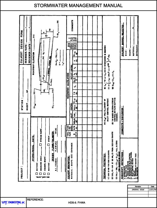
28.48.090 Culvert Design Form.
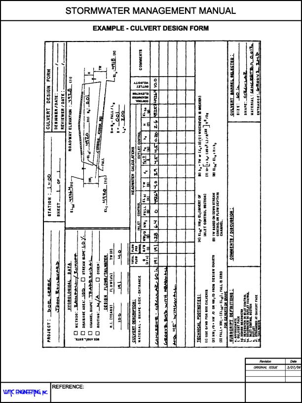
The Culvert Design Form, shown in Figure 28.48.090, has been formulated to guide the user through the design process. Summary blocks are provided at the top of the form for the project description and the designer’s identification. Summaries of hydrologic data are also included. At the top right is a small sketch of the culvert with blanks for inserting important dimensions and elevations.
The central portion of the design form contains lines for inserting the trial culvert description and calculating the inlet and outlet control headwater elevations. Space is provided at the lower center for comments and at the lower right for a description of the culvert barrel selected.
The first step in the design process is to summarize all known data for the culvert at the top of the Culvert Design Form. This information will have been collected or calculated prior to performing the actual culvert design. The next step is to select a preliminary culvert material, shape, size, and entrance type. The user then enters the design flow rate and proceeds with the inlet control calculations.
The Culvert Design Form is also included in Chapter 28.68 GJMC as Standard Form 4.
(Res. 40-08 (§ 1203.3), 3-19-08)
28.48.100 Inlet control calculation.
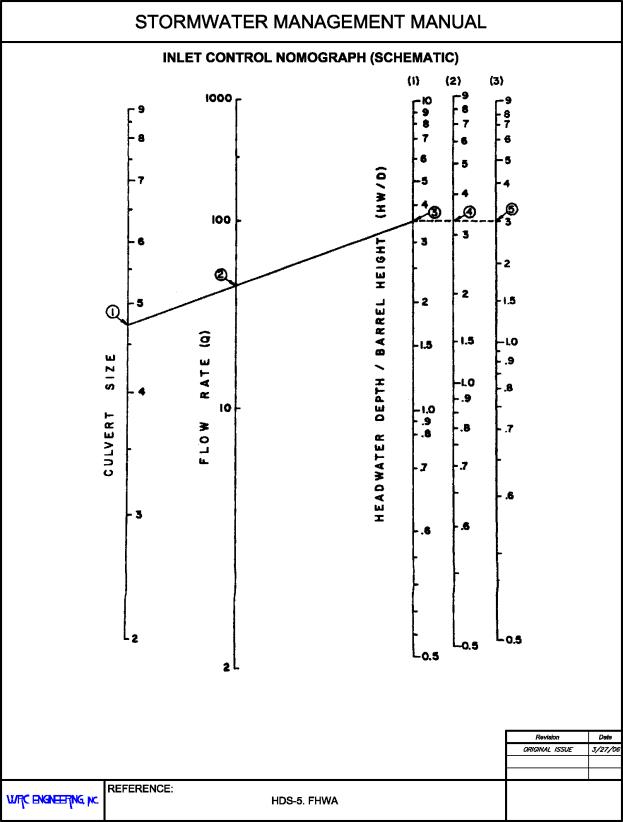
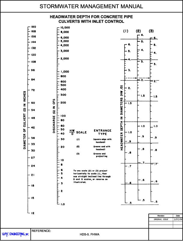
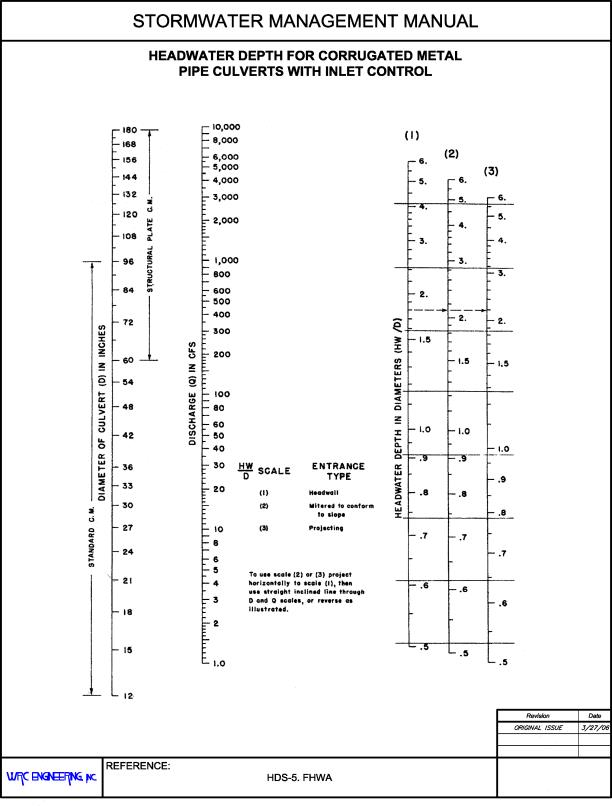
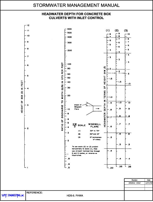
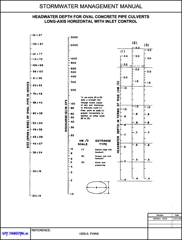
The inlet control calculations determine the headwater elevation required to pass the design flow through the selected culvert configuration in inlet control. The approach velocity head may be included as part of the headwater, if desired. Inlet control nomographs are used in the design process. Inlet control nomographs for typical configurations are included at the end of this section, Figures 28.48.100(b) through 28.48.100(e). For all other situations, refer to the FHWA’s HDS-5. For the following discussion, refer to the schematic inlet control nomograph shown in Figure 28.48.100(a).
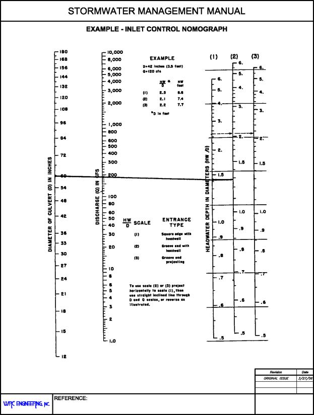
(a) Step 1. Locate the selected culvert size (point 1) and flow rate (point 2) on the appropriate scales of the inlet control nomograph. For box culverts, the flow rate per foot of barrel width is used.
(b) Step 2. Using a straightedge, carefully extend a straight line from the culvert size (point 1) through the flow rate (point 2) and mark a point on the first headwater/culvert height (HW/D) scale (point 3). The first HW/D scale is also a turning line.
(c) Step 3. Each scale represents a different inlet type. If another HW/D scale is required, extend a horizontal line from the first HW/D scale to the desired scale and read the result.
(d) Step 4. Multiply HW/D by the culvert height, D, to obtain the required headwater depth, HW, from the invert of the control section to the energy grade line. If the approach velocity is neglected, HW equals the required headwater depth, HWi. If the approach velocity is included in the calculations, deduct the approach velocity head from HW to determine HWi.
(e) Step 5. Calculate the required depression (FALL) of the inlet control section below the stream bed as follows:
|
|
(28.48-1) |
|
|
(28.48-2) |
Where:
|
HWd |
= |
design headwater depth (ft.) |
|
ELhd |
= |
design headwater elevation (ft.) |
|
ELsf |
= |
elevation of the stream bed at the face (ft.) |
|
HWi |
= |
required headwater depth (ft.) |
Possible results and consequences of this calculation are:
(1) If the FALL is negative or zero, set FALL equal to zero and proceed to step 6.
(2) If the FALL is positive, the inlet control section invert must be depressed below the streambed at the face by that amount. If the FALL is acceptable, proceed to step 6.
(3) If the FALL is positive and greater than is judged to be acceptable, select another culvert configuration and begin again at step 1.
(f) Step 6. Calculate the inlet control section invert elevation as follows:
|
|
(28.48-3) |
where ELi is the invert elevation at the face of a culvert or at the throat of a culvert with a tapered inlet.
(Res. 40-08 (§ 1203.4), 3-19-08)
28.48.110 Outlet control calculation.
The outlet control calculations result in the headwater elevation required to convey the design discharge through the selected culvert in outlet control. The approach and downstream velocities may be included in the design process, if desired. Critical depth charts and outlet control nomographs are used in the design process. Critical depth charts and outlet control nomographs for typical configurations are included at the end of this section, Figures 28.48.110(a) through 28.48.110(g). For all other situations, refer to the FHWA’s HDS-5. For illustration, refer to the schematic critical depth chart and outlet control nomograph shown in Figures 28.48.110(h) and 28.48.110(i), respectively.
(a) Determine the tailwater depth, TW, above the outlet invert at the design flow rate. This is obtained from backwater or normal depth calculations, or from field observations.
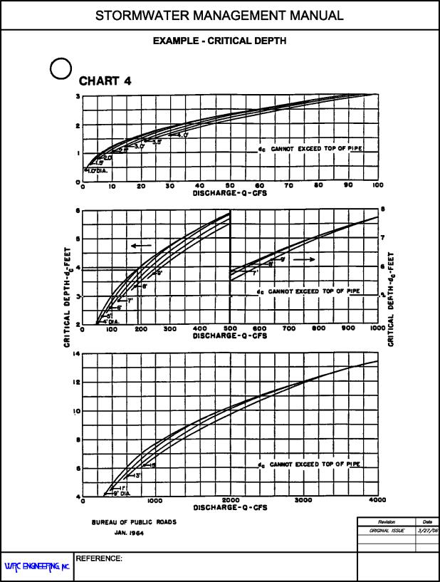
(b) Enter the appropriate critical depth chart, Figure 28.48.110(h), with the flow rate and read the critical depth, dc. The critical depth, dc, cannot exceed the culvert diameter, D.
The dc curves are truncated for convenience when they converge. If an accurate dc is required for dc > .9D consult the Handbook of Hydraulics or other hydraulic reference.
(c) Calculate (dc + D)/2.
(d) Determine the depth from the culvert outlet invert to the hydraulic grade line, ho.
ho = TW or (dc + D)/2, whichever is larger.
(e) From Table 28.48.110, obtain the appropriate entrance loss coefficient, Ke, for the culvert inlet configuration.
(f) Determine the head losses through the culvert barrel, H, using the outlet control nomograph, Figure 28.48.110(i).
(1) Required Manning’s n values are presented in Table 28.40.050 of Chapter 28.40 GJMC, Storm Drain Systems. If the Manning’s n value given in the outlet control nomograph is different than the required Manning’s n for the culvert, adjust the culvert length using the formula:
|
|
(28.48-4) |
Where:
|
L1 |
= |
adjusted culvert length (ft.) |
|
L |
= |
actual culvert length (ft.) |
|
n1 |
= |
desired Manning’s n value |
|
n |
= |
Manning’s n value from the outlet control chart |
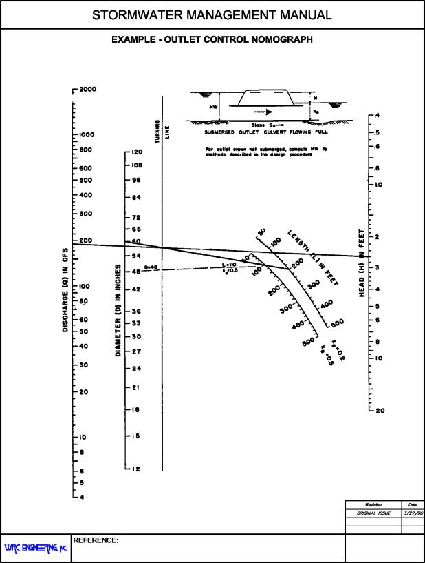
(2) Using a straightedge, connect the culvert size (point 1) with the culvert length on the appropriate ke scale (point 2). This defines a point on the turning line (point 3).
(3) Again using the straightedge, extend a line from the discharge (point 4) through the point on the turning line (point 3) to the head loss, H, scale. H is the energy loss through the culvert, including entrance, friction, and outlet losses.
Careful alignment of the straightedge is necessary to obtain good results from the outlet control nomograph.
(g) Calculate the required outlet control headwater elevation, ELho.
|
|
(28.48-5) |
where ELo is the invert elevation at the outlet.
(h) If the outlet control headwater elevation exceeds the design headwater elevation, a new culvert configuration must be selected and the process repeated. Generally, an enlarged barrel will be necessary since inlet improvements are of limited benefit in outlet control.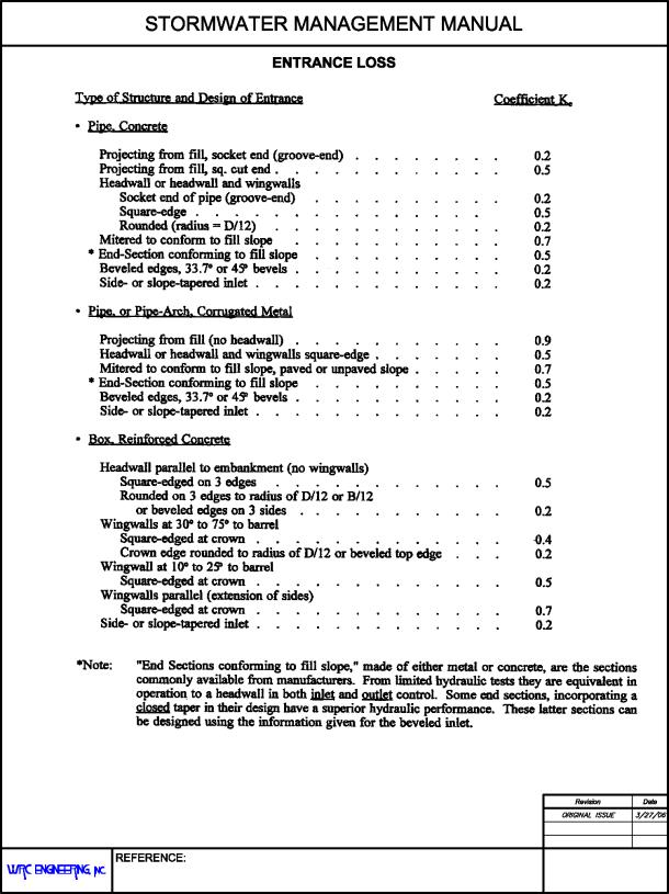
TABLE 28.48.110
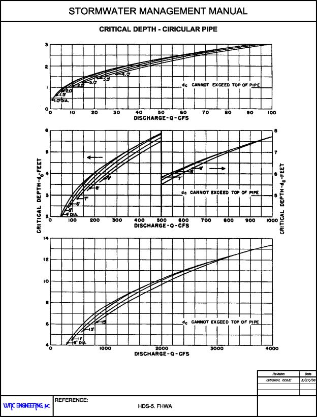
FIGURE 28.48.110(a)
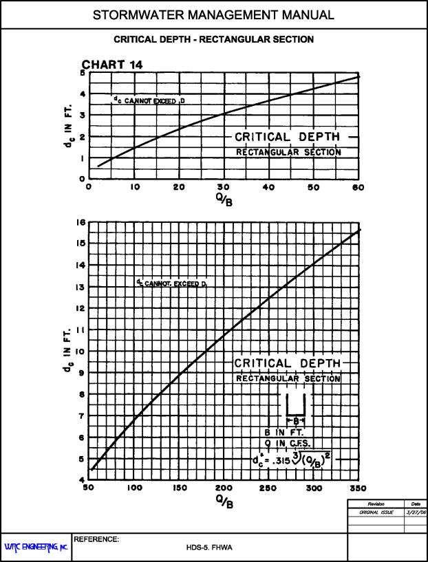
FIGURE 28.48.110(b)
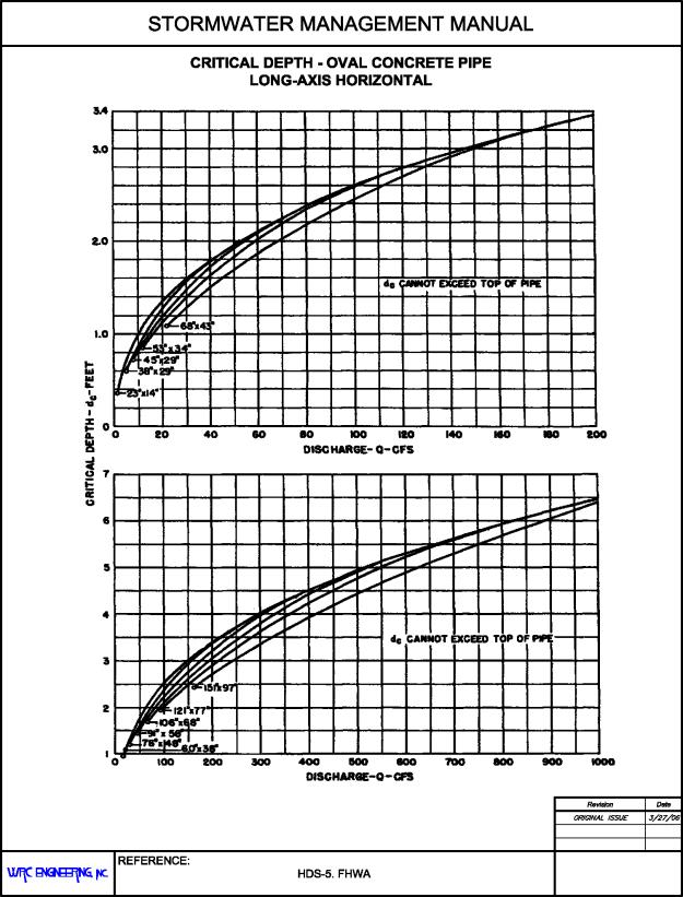
FIGURE 28.48.110(c)
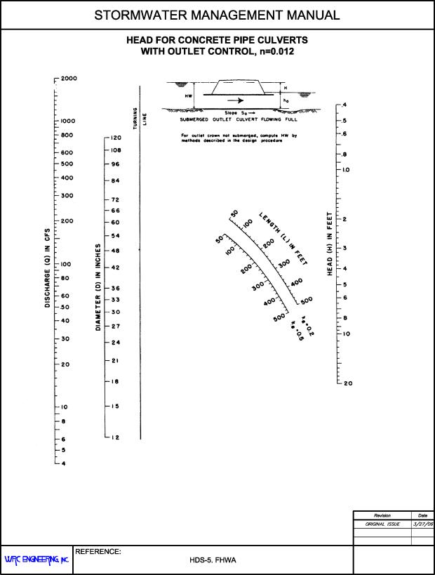
FIGURE 28.48.110(d)
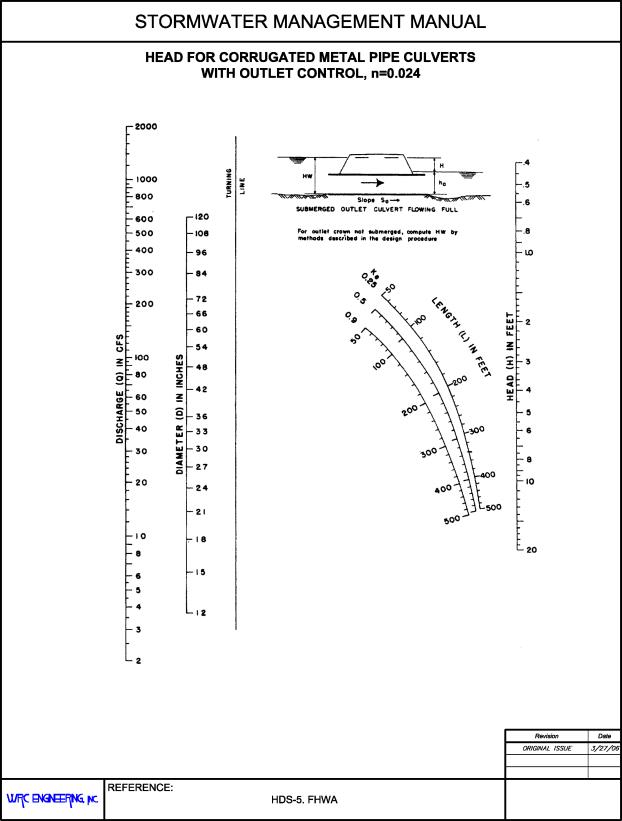
FIGURE 28.48.110(e)
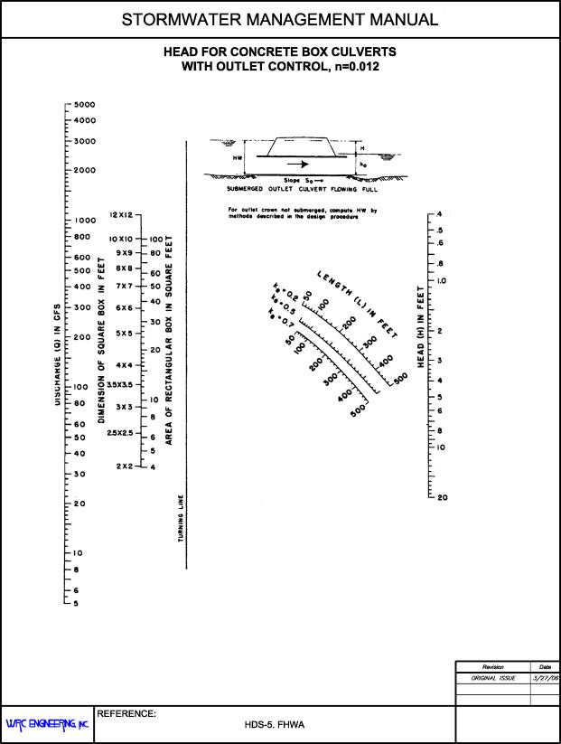
FIGURE 28.48.110(f)
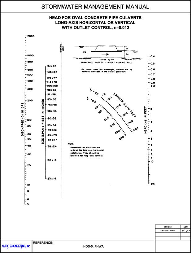
FIGURE 28.48.110(g)
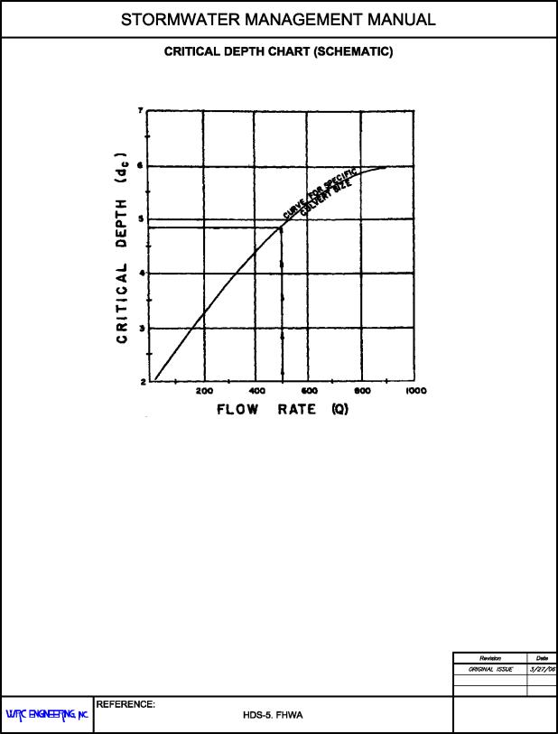
FIGURE 28.48.110(h)
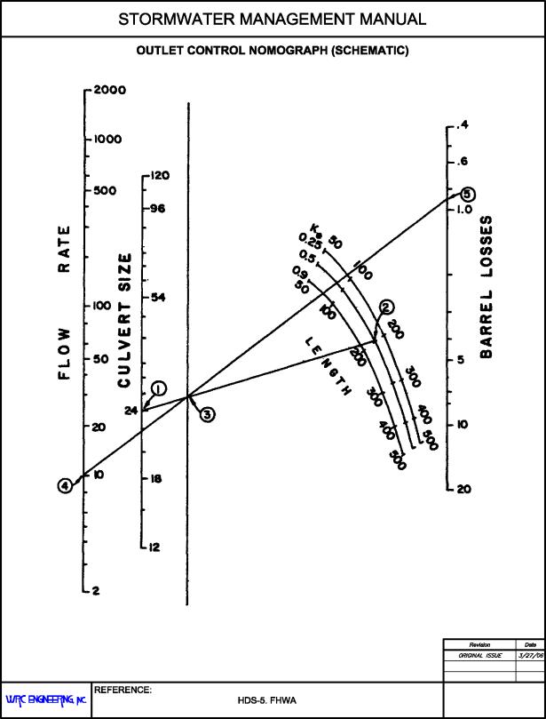
FIGURE 28.48.110(i)
(Res. 40-08 (§ 1203.5), 3-19-08)
28.48.120 Evaluation of results.
Repeat the design process until an acceptable culvert configuration is determined. If the culvert selected will not fit the site, return to the design process and select another culvert. Compare the headwater elevations calculated for inlet and outlet control. The higher of the two is designated the controlling headwater elevation. The culvert can be expected to operate with that higher headwater for at least part of the time.
If outlet control governs and the headwater depth is less than 1.2D, it is possible that the barrel flows partly full through its entire length. In this case, caution shall be used in applying the approximate method of setting the downstream elevation based on the greater of tailwater or (dc + D)/2. If an accurate headwater is necessary, backwater calculations shall be used to check the result from the approximate method. If the headwater depth falls below 0.75D, the approximate method shall not be used.
Due to problems arising from topography and other considerations, the actual design of a culvert installation is more difficult than the simple process of sizing culverts. However, the process presented herein shall be followed to ensure that some special problem is not overlooked. Several combinations of entrance types, invert elevations, and pipe diameters shall be tried to determine the most economic design that will meet the conditions imposed by topography and engineering.
(Res. 40-08 (§ 1203.6), 3-19-08)
28.48.130 Outlet velocity calculation.
The outlet velocity is calculated as follows:
(a) If the controlling headwater is based on inlet control, determine the normal depth and velocity in the culvert barrel. The velocity at normal depth is assumed to be the outlet velocity.
(b) If the controlling headwater is in outlet control, determine the area of flow at the outlet based on the barrel geometry and the following:
(1) Critical depth if the tailwater is below critical depth.
(2) Tailwater depth if the tailwater is between critical depth and the top of the barrel.
(3) Height of the barrel if the tailwater is above the top of the barrel.
(Res. 40-08 (§ 1203.7), 3-19-08)
28.48.140 Computer applications.
Although the nomographs discussed in this chapter are still used, engineers are increasingly designing culverts using computer applications. Among these applications are the FHWA’s HY8 Culvert Analysis and numerous proprietary applications. If a computer application other than HY8 is to be used, the designer must first submit documentation of the program to the local jurisdiction for approval.
(Res. 40-08 (§ 1203.8), 3-19-08)
28.48.150 Outlet protection.
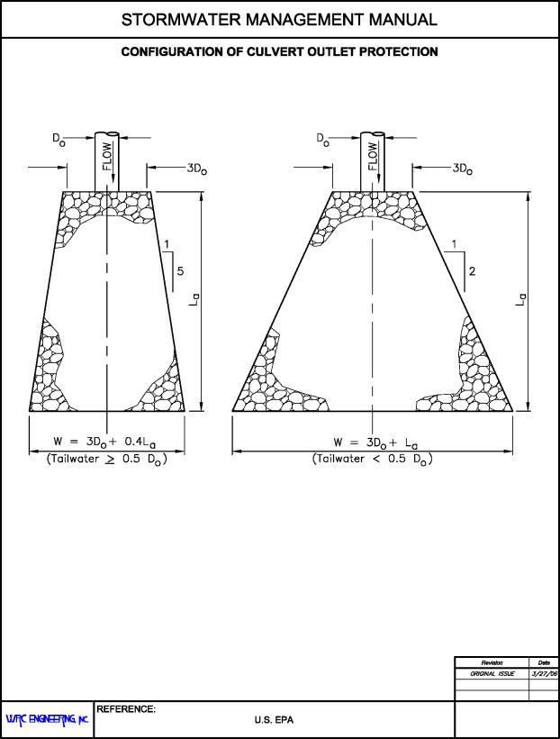
Table 28.32.310 in Chapter 28.32 GJMC, Open Channels, presents maximum permissible mean channel velocities. For unlined channels, erosion protection in the form of a horizontal riprap lined apron is required for all culvert outlets when the outlet velocity exceeds the values presented in Table 28.32.310. The length of the apron, La, is determined using the following empirical relationships that were developed for the U.S. Environmental Protection Agency:
|
|
(28.48-6) |
and
|
|
(28.48-7) |
Where:
|
D0 |
= |
maximum inside culvert width (ft.) |
|
Q |
= |
pipe discharge (cfs) |
|
TW |
= |
tailwater depth (ft.) |
Where there is no well-defined channel downstream of the apron, the width, W, of the apron shall be as follows, as shown in Figure 28.48.150(a):
|
|
(28.48-8) |
and
|
|
(28.48-9) |
The width of the apron at the culvert outlet shall be at least three times the culvert width.
Where there is a well-defined channel downstream of the apron, the bottom width of the apron shall be at least equal to the bottom width of the channel and the lining shall extend at least 1.0 foot above the tailwater elevation and at least two-thirds of the vertical conduit dimension above the invert.
The side slopes shall be 2:1 or flatter, the bottom grade shall be level, and there shall be overfall at the end of the apron or culvert.
The median stone diameter required, d50, is determined from the following equation:
|
|
(28.48-10) |
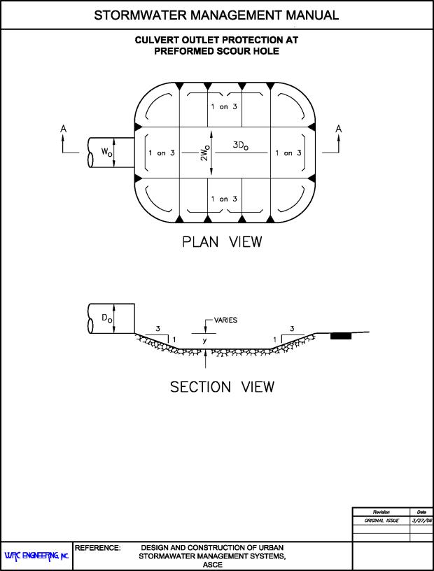
Preformed scour holes may be used where flat aprons are impractical. Figure 28.48.150(b) shows a general design of a scour hole. The stone diameter is determined using the following equations:
|
|
(28.48-11) |
and
|
|
(28.48-12) |
where y = depth of scour hole below culvert invert.
When riprap is not an option or is unavailable, the engineer has other natural and manmade materials available for use in erosion protection. Other options include gabions, concrete, recycled concrete, shotcrete, masonry, geotextiles, and woody plants. Outlet protection measures other than riprap may be used if first approved by the local jurisdiction.
(Res. 40-08 (§ 1203.9), 3-19-08)
28.48.160 Trash/safety racks.
(a) The use of typical gratings at inlets to culverts and long underground pipes shall be considered on an individual basis. While there is a sound argument for the use of gratings for safety reasons, field experience has clearly shown that when the culvert is operating during heavy runoff, normal gratings often become clogged and the culvert is rendered ineffective. A general rule of thumb is that if it will be possible to see daylight from one side of the culvert to the other, a trash/safety rack will not be needed. At entrances to longer culverts, a trash rack is necessary. Engineering judgment shall be used to determine if trash/safety racks will be used. Factors which may influence whether or not trash/safety racks will be used include the following:
(1) Tributary land use (urban, rural, forest).
(2) Location (urban/rural).
(3) Design flow.
(4) Size of culvert.
(5) Anticipated debris loading.
(6) Performance of nearby existing structures.
(b) Trash/safety racks shall be required for all culverts located adjacent to schools, parks, playgrounds, and other recreational facilities where the pipe alignment or length does not allow for an unobstructed view through the culvert. Where it is found that trash/safety racks are needed, the open area through the grate at the design water surface shall be four times the design flow area of the culvert.
(Res. 40-08 (§ 1203.10), 3-19-08)
28.48.170 Culvert inlets.
One of the most important considerations in the design of a culvert is the inlet configuration. Since the natural channel is usually wider than the culvert barrel, the culvert inlet edge represents a flow contraction and may be the primary flow control. The provision of a more gradual flow transition will lessen the energy loss and thus create a more hydraulically efficient inlet condition. The inlet type can also increase the overall structural integrity by retaining fill slope and preventing inlet scour with subsequent undermining of the culvert. All culverts shall be designed either with headwalls and wingwalls or flared-end sections at the inlet and outlet.
A multitude of different inlet configurations are utilized on culvert barrels. These include both prefabricated and constructed-in-place installations. Commonly used inlet configurations include projecting culvert barrels, cast-in-place concrete headwalls, precast or prefabricated end sections, and culvert ends mitered to conform to the fill slope. Structural stability, aesthetics, erosion control, and fill retention are considerations in the selection of various inlet configurations.
(Res. 40-08 (§ 1204), 3-19-08)
28.48.180 Projecting inlets.
Projecting inlets vary greatly in hydraulic efficiency and adaptability to requirements with the type of pipe material used. The primary advantage of projecting inlets is relatively low cost. Corrugated metal pipe projecting inlets have limitations which include low efficiency and susceptibility to damage. A projecting entrance of corrugated metal pipe is equivalent to a sharp-edged entrance with a thin wall and has an entrance coefficient of approximately 0.9, Table 28.48.110. Bell-and-spigot concrete pipe or tongue-and-groove concrete pipe with the bell end or grooved end used as the inlet section are quite efficient hydraulically, having an entrance coefficient of approximately 0.2, Table 28.48.110. For concrete pipe that has been cut, the entrance is square-edged, the entrance coefficient is approximately 0.5, Table 28.48.110.
(Res. 40-08 (§ 1204.1), 3-19-08)
28.48.190 Inlets with headwalls.
Headwalls may be used for a variety of reasons, including increasing the efficiency of the inlet, providing embankment stability, and providing embankment protection against erosion. The relative efficiency of the inlet varies with the pipe material used. Corrugated metal pipe in a headwall is essentially a squared-edged entrance with an entrance coefficient of approximately 0.5. The entrance losses may be reduced by rounding the entrance. For tongue-and-groove or bell-end concrete pipe, little increase in hydraulic efficiency is realized by adding a headwall. The primary reasons for using headwalls are embankment protection and ease of maintenance.
Wingwalls are used where the side slopes of the channel adjacent to the entrance are unstable and where the culvert is skewed to the normal channel flow. Little increase in hydraulic efficiency is realized with the use of wingwalls, regardless of the pipe material used and, therefore, the use shall be justified for reasons other than an increase in hydraulic efficiency.
(Res. 40-08 (§ 1204.2), 3-19-08)
28.48.200 Tapered inlets.
Inlet configuration is one of the prime factors influencing the performance of a culvert operating under inlet control. Inlet edges can cause severe contraction of the flow, as in the case of a thin edge, projecting inlet. In a flow contraction, the effective cross-sectional area of the barrel may be reduced to about one-half of the actual available barrel area. As the inlet configuration is improved, the flow contraction is reduced, thus improving the performance of the culvert.
A tapered inlet is a flared culvert inlet with an enlarged face section and a hydraulically efficient throat section. Tapered inlets improve culvert performance by providing a more efficient control section (the throat). However, tapered inlets are not recommended for use on culverts flowing under outlet control because the simple beveled edge is of equal benefit. The two most common improved inlets are the side-tapered inlet and the slope-tapered inlet. FHWA’s HDS-5 provides guidance on the design of improved inlets.
(Res. 40-08 (§ 1204.3), 3-19-08)
28.48.210 Bridge hydraulics.
Bridges are required across nearly all open channels sooner or later and, therefore, sizing the bridge openings is of great importance. Open channels with improperly designed bridges will either have excessive scour or deposition or not be able to carry the design flow. Confining flood waters by bridges can cause excessive backwater resulting in flooding of upstream property, backwater damage suits, overtopping of roadways, costly maintenance, or even loss of a bridge. Bridge openings shall be designed to have as little effect on the flow characteristics as reasonable, consistent with good design and economics.
(Res. 40-08 (§ 1205), 3-19-08)
28.48.220 Hydraulic analysis.
The hydraulic analysis procedures described in this chapter are suitable, although methods such as FHWA HY-4 or HEC-RAS are acceptable as well. If a computer application other than HY-4 or HEC-RAS is to be used, the designer must first submit documentation of the program to the local jurisdiction for approval. The preliminary assessment approach described below is presented in greater detail in the FHWA Hydraulics of Bridge Waterways.
(Res. 40-08 (§ 1205.1), 3-19-08)
28.48.230 Expression of backwater.
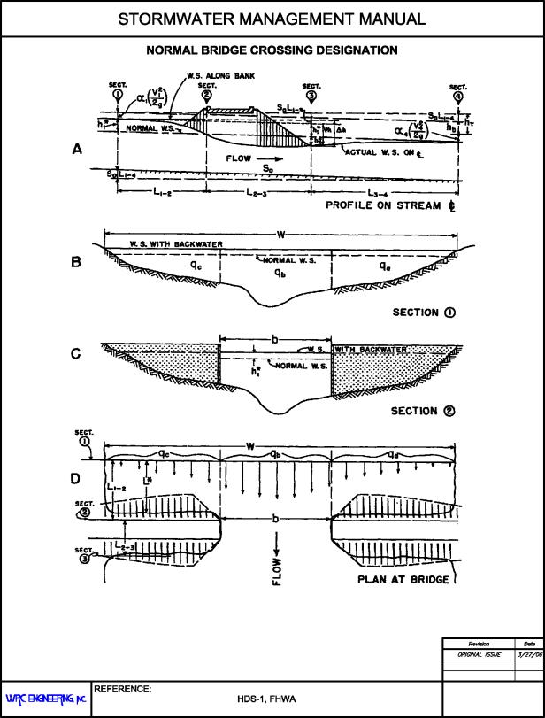
A practical expression for backwater has been formulated by applying the principle of conservation of energy between the point of maximum backwater upstream from the bridge and a point downstream from the bridge at which normal stage has been reestablished, as shown in Section 4 of Figure 28.48.230. The expression is reasonably valid if the channel in the vicinity of the bridge is reasonably uniform, the gradient of the bottom is approximately constant between Sections 1 and 4, there is no appreciable erosion of the bed in the constriction due to scour, and the flow is subcritical.
The expression for computation of backwater upstream from the bridge constricting the flow is as follows:
|
|
(28.48-13) |
Where:
|
h1* |
= |
total backwater (ft.) |
|
K* |
= |
total backwater coefficient |
|
|
= |
kinetic energy coefficient |
|
An2 |
= |
gross water area in constriction measured below normal stage (ft.2) |
|
Vn2 |
= |
average velocity in constriction or Q/An2(ft./s). The velocity Vn2 is not an actual measurable velocity but represents a reference velocity readily computed for both model and field structures |
|
A4 |
= |
water area at Section 4 where normal stage is reestablished (ft.2) |
|
A1 |
= |
total water area at Section 1 including backwater (ft.2) |
|
g |
= |
acceleration constant (32.2 ft./sec2) |
To compute backwater by Equation 28.48-13, it is necessary to obtain the approximate value of h1* by using the first part of the equation:
|
|
(28.48-14) |
The value of A1 in the second part of Equation 28.48-13, which depends on h1*,can then be determined. This part of the expression represents the difference in kinetic energy between Sections 4 and 1, expressed in terms of the velocity head V2n2/2g.Equation 28.48-13 may appear cumbersome, but it was set up as shown to permit omission of the second part when the difference in kinetic energy between Sections 4 and 1 is small enough to be insignificant in the final result.
To permit the designer to readily recognize cases in which the kinetic energy term may be ignored, the following guides are provided: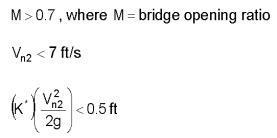
If values meet all three conditions, the backwater obtained from Equation 28.48-14 can be considered sufficiently accurate. Should one or more of the values not meet the conditions set forth, it is required to use Equation 28.48-13 in its entirety. The use of the guides is further demonstrated in the examples given in FHWA Hydraulics of Bridge Waterways that shall be used in all bridge design work.
(Res. 40-08 (§ 1205.2), 3-19-08)
28.48.240 Backwater coefficient.
The value of the overall backwater coefficient K*, which was determined experimentally, varies with the following:
(a) Stream constriction as measured by the bridge opening ratio, M.
(b) Type of bridge abutment: wingwall, spill through, etc.
(c) Number, size, shape, and orientation of piers in the constriction.
(d) Eccentricity or asymmetric position of bridge with respect to the floodplain.
(e) Skew (bridge crosses floodplain at other than 90-degree angle).
The overall backwater coefficient K* consists of a base curve coefficient, Kb, to which are added incremental coefficients to account for the effect of piers, eccentricity, and skew. The value of K* is primarily dependent on the degree of constriction of the flow but also changes to a limited degree with the other factors.
(Res. 40-08 (§ 1205.3), 3-19-08)
28.48.250 Effect of M and abutment shape (base curves).
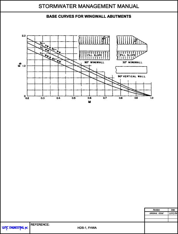
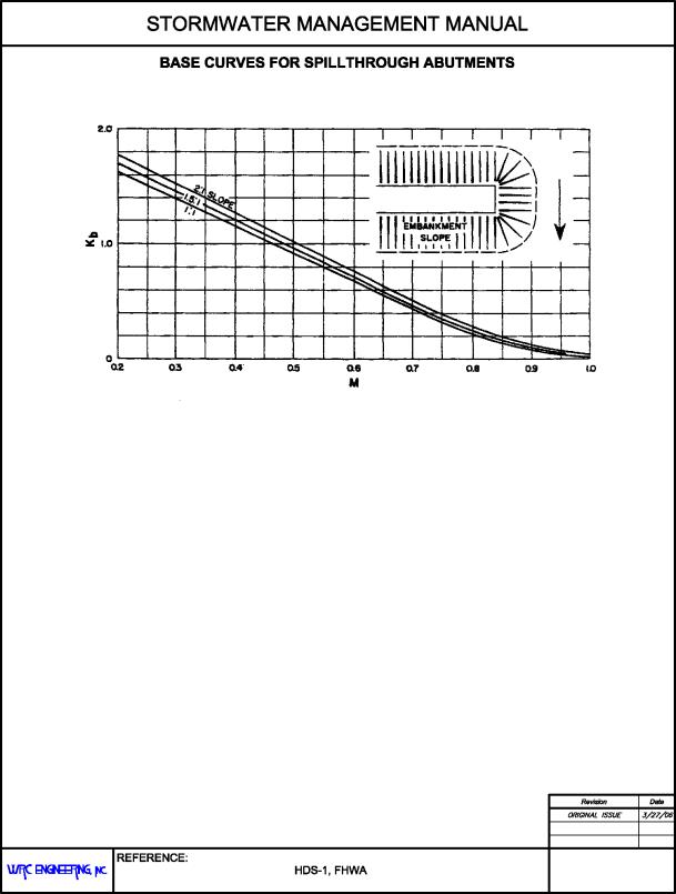
Figure 28.48.250(a) shows the base curves for backwater coefficient, Kb, plotted with respect to the opening ratio, M, for several wingwall abutments and vertical wall type. Note how the coefficient Kb increases with channel constriction. The several curves represent different angles of wingwalls as can be identified by the accompanying sketches. The lower curves represent the better hydraulic shapes.
Figure 28.48.250(b) shows the relation between the backwater coefficient, Kb, and M for spill-through abutments for three embankment slopes. A comparison of the three curves indicates that the coefficient is little affected by embankment slope. Figures 28.48.250(a) and 28.48.250(b) are “base curves” and Kb is referred to as the “base curve coefficient.” The base curve coefficients apply to normal crossings for specific abutment shapes but do not include the effect of piers, eccentricity, or skew.
(Res. 40-08 (§ 1205.4), 3-19-08)
28.48.260 Effect of piers (normal crossings).
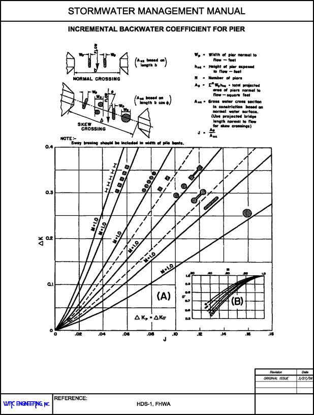
The effect on the backwater from introduction of piers in a bridge constriction has been treated as an incremental backwater coefficient designated ΔKp, which is added to the base curve coefficient when piers are a factor. The value of the incremental backwater coefficient, ΔKp, is dependent on the ratio that the area of the piers bears to the gross area of the bridge opening; the type of piers (or pilings in the case of pile bents); the value of the bridge opening ratio, M; and the angularity of the piers with the direction of flood flow. The ratio of the water area occupied by piers, Ap, to the gross water area of the constriction, An2, both based on the normal water surface, has been assigned the letter J. In computing the gross water area, An2, the presence of piers in the constriction is ignored. The incremental backwater coefficient for the more common types of piers and pile bents can be obtained from Figure 28.48.260. The procedure is to enter Chart A, Figure 28.48.260, with the proper value of J and read ΔK and obtain the correction factor σ from Chart B, Figure 28.48.260, for opening ratios other than unity. The incremental backwater coefficient is then:
|
|
(28.48-15) |
The incremental backwater coefficients for piers can, for all practical purposes, be considered independent of diameter, width, or spacing but shall be increased if there are more than five piles in a bent. A bent with 10 piles shall be given a value of ΔKp about 20 percent higher than those shown for bents with five piles. If there is a good possibility of trash collecting on the piers, it is advisable to use a value greater than the pier width to include the trash. For a normal crossing with piers, the total backwater coefficient becomes:
|
K* = Kb (Figures 28.48.250(a) or 28.58.250(b) + ΔKp (Figure 28.48.260) |
(28.48-16) |
(Res. 40-08 (§ 1205.5), 3-19-08)
28.48.270 Bridge sizing and design.
The method of planning for bridge openings must include water surface profiles and hydraulic gradient analyses of the channel for the 100-year event. Once this hydraulic gradient is established without the bridge, the maximum reasonable effect on the channel flow by the bridge shall be determined.
(a) Bridge Design Standards. All bridges shall be designed to pass the 100-year design flow and meet all applicable floodplain regulations. The 100-year water surface elevation within the bridge shall be a minimum of 1.0 foot below the bridge low chord.
Where bridge abutments and foundations are located below the 100-year water surface elevation, concrete wingwalls at angles of 40 degrees to 60 degrees shall be tied to the existing side slopes to prevent erosion behind the abutments.
Where supercritical flow exists in a lined channel, the bridge shall have no influence on the flow. There shall be no encroachment into the 100-year water surface elevation.
The design and supporting calculations for both private bridges and low water crossings shall be prepared and certified by a Colorado Registered Professional Engineer.
(b) Design Procedure. The following is a brief step-by-step outline for determination of backwater produced by a bridge constriction:
(1) Determine the magnitude and frequency of the discharge for which the bridge is to be designed.
(2) Determine the stage of the stream at the bridge site for the design discharge.
(3) Plot representative cross-section of stream for design discharge at Section 1. If the stream is essentially straight and the cross-section substantially uniform in the vicinity of the bridge, the natural cross-section of the stream at the bridge site may be used for this purpose.
(4) Subdivide the above cross-section according to marked changes in depth of flow and roughness. Assign values of Manning’s roughness coefficient, n, to each subsection. Typical roughness coefficients can be found in Table 28.32.040(d) of Chapter 28.32, Open Channels. Careful judgment is necessary in selecting these values.
(5) Compute conveyance and then discharge in each subsection.
(6) Determine the value of the kinetic energy coefficient.
(7) Plot the natural cross-section under the proposed bridge based on normal water for design discharge and compute the gross water area, including area occupied by piers.
(8) Compute the bridge opening ratio, M, observing modified procedure for skewed crossings.
(9) Obtain the value of Kb from the appropriate base curve.
(10) If piers are involved, compute the value of J and obtain the incremental coefficient, ΔKp.
(11) If eccentricity is severe, compute the value of eccentricity and obtain the incremental coefficient, ΔKe.
(12) If a skewed crossing is involved, observe proper procedure in previous steps, then obtain the incremental coefficient, ΔKs, for proper abutment type.
(13) Determine the total backwater coefficient, K*, by adding incremental coefficients to the base curve coefficient, Kb.
(14) Compute the backwater by Equation 28.48-13.
(15) Determine the distance upstream to where the backwater effect is negligible.
Detailed steps illustrated by examples are presented in FHWA Hydraulics of Bridge Waterways.
(Res. 40-08 (§ 1206), 3-19-08)
28.48.280 Example application – Culvert sizing.
(a) Problem. Determine the culvert size necessary to convey the 100-year discharge in Doe Creek beneath John Boulevard. The results of the analysis are shown in the Culvert Design Form of Figure 28.48.280(a).
|
Top of road elevation = 4,928 ft. |
|
Culvert inlet elevation = 4,920 ft. |
|
Culvert outlet elevation = 4,918 ft. |
|
Culvert length = 200 ft. |
|
Inlet – Groove end with headwall and wingwalls at 45 degrees |
|
Outlet – Groove end with headwall and wingwalls at 45 degrees |
|
Flow = 191 cfs |
|
Tailwater depth = 4 ft. |
(b) Solution.
(1) Step 1. Assume a reinforced concrete pipe diameter and determine the headwater to depth ratio for inlet control from Figure 28.48.100(b). Assume a reinforced concrete pipe diameter of five feet. Given are a 100-year design flow of 191 cfs and a grooved end with headwall inlet configuration.
|
HW/D = 1.28 |
See Figure 28.48.280(b) |
(2) Step 2. Calculate the required headwater depth assuming inlet control conditions. Multiply the pipe diameter times the headwater to depth ratio.
|
Headwater = HWi = D*(HW/D) = 5.0*1.28 = 6.4 ft. |
(3) Step 3. Calculate the required headwater elevation assuming inlet control conditions.
|
FALL = 0, since the culvert invert is at grade |
|
HWi = HWd |
|
ELi = ELsf |
|
ELhd = ELi + HWi = 4,920 + 6.4 = 4,926.4 ft. |
(4) Step 4. Estimate the critical depth, dc, in the culvert from Figure 28.48.110(a).
|
dc = 3.9 ft. (see Figure 28.48.280(c)) |
(5) Step 5. Since the tailwater depth is less than the culvert diameter, compute the estimated water depth at the culvert outlet assuming the tailwater does not control the outlet conditions.
|
Outlet Depth = (dc + D)/2 = (3.9+5.0)/2 = 4.5 ft. |
(6) Step 6. Determine the flow depth at the culvert outlet, ho. The estimated depth is the maximum value of the tailwater depth and the water depth assuming no tailwater.
|
4.5 ft. > 4.0 ft., therefore ho = 4.5 ft. |
(7) Step 7. Estimate the head, H, for outlet control conditions from Figure 28.48.110(d).
|
H = 2.6 ft. (see Figure 28.48.280(d)) |
(8) Step 8. Calculate the required outlet control headwater elevation, ELho.
|
ELho = ELo + H + ho = 4,918 + 2.6 + 4.5 = 4,925.1 ft. |
(9) Step 9. Determine if the culvert is under inlet control or outlet control and provide the resulting control headwater elevation and depth.
|
ELhd > ELho (4,926.4 > 4,925.1), the culvert is under inlet control |
|
Control Headwater Elevation = 4,926.4 |
|
HW = 6.4 ft. |
(10) Step 10. Calculate the outlet velocity by an appropriate method and determine the amount of outlet protection needed, see GJMC 28.48.150.
|
v = 10.0 ft./s |
(Res. 40-08 (§ 1207), 3-19-08)


