Chapter 28.56
DETENTION AND RETENTION
Sections:
28.56.020 Detention versus retention.
28.56.030 Local detention facilities.
28.56.040 Regional detention facilities.
28.56.050 Drainage fee in lieu of detention.
28.56.070 Drainage fee calculation.
28.56.080 Detention for management of stormwater quality.
28.56.090 Design storm criteria.
28.56.100 Geometric requirements.
28.56.110 Dry basin bottom drainage.
28.56.120 Accessibility and maintenance.
28.56.130 Calculating storage volume available.
28.56.140 Groundcover and landscaping.
28.56.150 Freeboard requirements.
28.56.160 State Engineer’s Office.
28.56.170 Embankment protection.
28.56.180 Inlet and outlet design.
28.56.210 Hydrologic design methods and criteria.
28.56.240 Compensating detention analysis.
28.56.250 Over-detention analysis.
28.56.260 Hydraulic design of outlet works.
28.56.010 Introduction.
The main purpose of a detention basin is to store runoff and reduce peak discharge by allowing flow to be discharged later at a controlled rate, and within a reasonable time. This controlled discharge rate is based on either limited downstream capacity (regional and local facilities) or on a limit on the increase in flows over predevelopment conditions (local facilities only). Detention has been shown to be very beneficial in controlling flood peaks in an urbanized area. Use of detention includes local detention such as in-channel or within a parking lot, and regional detention, such as a large recreational lake or reservoir and off-line detention facilities. Regional and local detention facilities are more fully discussed below. Policy regarding detention and extended detention (retention) is found in GJMC 28.16.090 and 28.16.100.
It is important that any extended detention (retention) be supported by valid water rights that allows for retention without impacting any vested water rights on the stream system.
(Res. 40-08 (§ 1401), 3-19-08)
28.56.020 Detention versus retention.
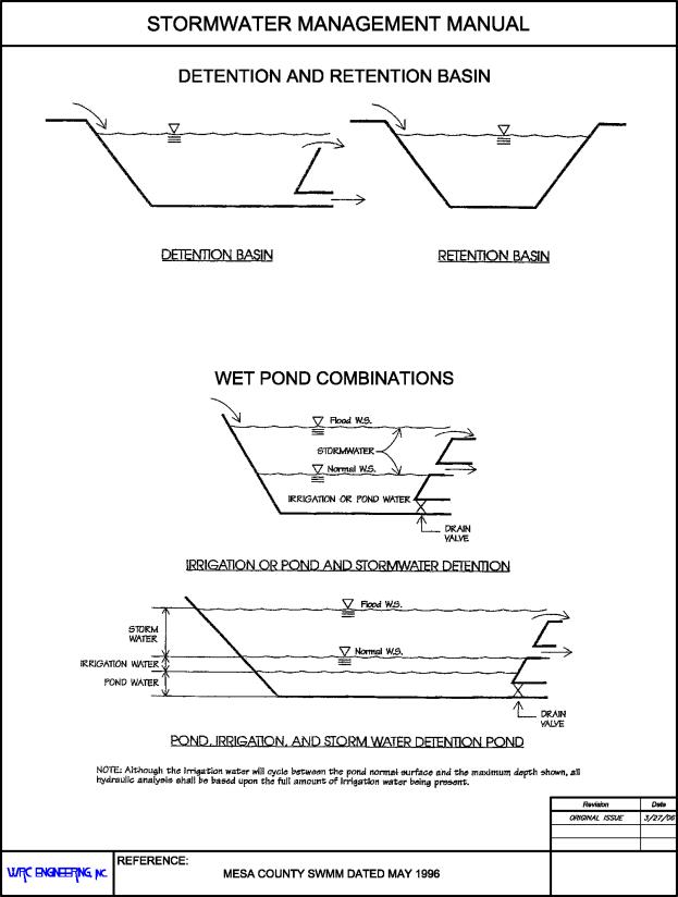
Stormwater storage reservoir types are numerous, but they essentially fit into one of two categories: detention or retention. The words “pond” and “basin” are used interchangeably when used in connection with both detention and retention reservoirs. A detention basin or pond detains water temporarily, releasing water through a pipe or channel by means of a weir, orifice, or pump. Because of its ability to release flow during inflow, the overall volume of storage required for a given storm event is reduced. Another advantage of the detention basin is the positive means of outflow, resulting in fewer problems with long-term ponding. A retention basin or pond retains water without any initial release during inflow. Once the storm event is over, pond drainage may occur due to evaporation and percolation into the soil. In some instances, retention basins may also involve a gated pipe or pump which is closed or inoperative during the storm event. However, if a gated pipe or pump is an available or desirable option, it would normally be advantageous to release water during stormwater inflow, which would change the basin from a retention basin to a detention basin. The difference in detention and retention basins is depicted in Figure 28.56.020.
The words “pond” and “basin” may be used to refer to reservoirs that remain dry outside of storm events, or store water for other purposes, e.g., irrigation, recreation, aesthetics, etc., in addition to receiving stormwater during storm events. Words “wet” and “dry” are used as prefixes to describe the condition of ponds and basins. However, a wet pond and dry basin each have a specific meaning.
Wet ponds may be desirable compared to dry basins in some circumstances. It may be that ample storage volume exists to provide an aesthetic, recreational, or irrigation pond below the required reservoir volume. Use of irrigation storage facilities for stormwater detention purposes must be reviewed by the appropriate jurisdiction(s) on a case-by-case basis. It is required that the stormwater reservoir volume provided must be in addition to the maximum expected base storage (irrigation or wet pond) volume. This is depicted in Figure 28.56.020.
(Res. 40-08 (§ 1402), 3-19-08)
28.56.030 Local detention facilities.
Local detention facilities are usually designed by and financed by developers or local property owners. The facilities are intended to allow development by protecting a site from existing flooding conditions or to protect downstream property from increased runoff caused by development. Two classes of local facilities are defined below.
(a) Local Minor Facilities. Local minor detention facilities are defined as serving a single development with a hydrologic basin smaller than or equal to 20 acres and are designed to mitigate the impact of increased runoff due to development. The outlet capacity is generally based on predevelopment hydrology, and the detention structures are generally small (0.01 to one acre-foot). Detention storage volume may be provided as small landscaped or turfed basins, parking lot storage, or a suitable combination of all.
(b) Local Major Facilities. Local major detention facilities are defined as serving more than a single development or serving hydrologic basins greater than 20 acres in size. These facilities may serve dual functions. They typically reduce existing flooding problems to allow more development and/or control increased runoff caused by additional development. These facilities may store significant flood volumes and will generally be funded by the developer. They may handle both off-site and on-site flows. Due to their larger size, these basins are designed much the same as regional detention facilities.
(Res. 40-08 (§ 1403.1), 3-19-08)
28.56.040 Regional detention facilities.
Regional detention facilities are those identified in the current Grand Valley Stormwater Master Management plan or as designated by local jurisdiction. Generally, these facilities control flow on major drainageways, are large in size, and are owned and maintained by public agencies. The purpose of these facilities is to significantly reduce downstream flows in order to maximize the capacity of existing systems and maintain flows at or below historic rates.
(Res. 40-08 (§ 1403.2), 3-19-08)
28.56.050 Drainage fee in lieu of detention.
The developer may be given the option of paying a drainage fee in lieu of providing adequate detention facilities. Such an option may be considered only if the developer completes an engineering analysis to show that all downstream facilities have adequate capacity to handle the undetained flows from the proposed development. If such option is allowed, this does not waive the requirements for drainage planning submittal requirements as outlined in Chapter 28.12 GJMC.
(Res. 40-08 (§ 1404), 3-19-08)
28.56.060 Drainage fee basis.
(a) For stormwater management purposes, charges assessed to existing and new development to offset cost of providing drainage facilities and services are typically categorized as an impact fee or a utility fee.
(b) An impact fee is based on the cost of upgrading drainage services within a watershed, shared among all new developments within the watershed. The basis for sharing costs can be as simple as the size of the water tap and as complex as calculating imperviousness of the property then making adjustments for various best management practices, such as detention. An impact fee is a one-time charge against new development.
(c) A utility fee is based on the cost of upgrading and maintaining drainage services within a watershed to meet current standards or level-of-service. A utility fee is often assessed to all properties, developed or not, and often is limited to providing maintenance of the system and minor capital improvements. Utility fees are normally charged on a monthly basis.
(d) Since the local jurisdiction charge is a fee in lieu of detention for new development, it is considered a limited impact fee. Reasonableness tests applied to impact fees include:
(1) The system impact fee shall be related to the amount of drainage improvements needed to meet local standards.
(2) The impact fee shall only cover capital and related (i.e., engineering, construction administration, etc.) costs for improvements.
(Res. 40-08 (§ 1404.1), 3-19-08)
28.56.070 Drainage fee calculation.
(a) The formula used by local jurisdictions to calculate drainage fee is of the form:
|
Drainage Fee ($) = B(CD – CH)A0.7 |
(28.56-1) |
Where:
|
B |
= |
Fee constant (established annually by City Council of local jurisdiction) |
|
CD |
= |
100-year runoff coefficient (expressed as a decimal) based on developed land use conditions |
|
CH |
= |
100-year runoff coefficient (expressed as a decimal) based on pre-developed land use conditions |
|
A |
= |
Area of development (acres) |
|
Assigning B = $14,000, A = 1 acre, CD = 0.60 and CH = 0.51, based on SCS Type C soils, and an imperviousness of two percent pre-developed and 50 percent developed, the fee in lieu of detention would be $1,260. |
||
(b) The equation used in Mesa County and the other local jurisdictions takes into account key factors for a fee in lieu of detention, such as:
(1) The fee is based on area.
(2) The fee takes into account imperviousness by using the rational method C values.
(3) The fee takes into account the difference between pre- and post-development runoff rates, which is the main function of on-site detention.
(c) The constant B needs to closely reflect the actual cost of providing detention, and must be changed with time as the need arises. Local jurisdictions will review this figure annually and make appropriate recommendations for its adjustment.
(Res. 40-08 (§ 1404.2), 3-19-08)
28.56.080 Detention for management of stormwater quality.
In addition to the primary purpose of detention and retention facilities to reduce peak flows, they can be adapted to enhance stormwater quality.
The outlet for a detention basin can be designed to allow for a slower rate of release and thus provide time for particulate pollutants to settle out of the stormwater. Such basins are called extended detention basins (EDB). It is recommended that an EDB outlet be designed to completely drain a full basin in 48 hours, allowing for the removal of a significant portion of insoluble pollutants with proper operation and maintenance.
A retention pond (RP) is a sedimentation facility designed to have a permanent water pool. This pool of water is mixed with stormwater during storm runoff events from frequently occurring storms and allows for sedimentation and thus water quality enhancement to occur.
For frequently occurring storms, both EDBs and RPs capture the total runoff as a surcharge. However, in the case of RPs, the stormwater is allowed to mix with the permanent pool water as it rises above the permanent pool level. All surcharged water above the permanent pool level is to be released over 48 hours. Details related to the design of EDBs and RPs can be found in Chapter 28.60 GJMC, Construction Site Stormwater Runoff Control, and Chapter 28.64 GJMC, Post-Construction Stormwater Management.
For the 100-year detention, the water quality volume is considered to be a part of the volume required for detention purposes.
(Res. 40-08 (§ 1405), 3-19-08)
28.56.090 Design storm criteria.
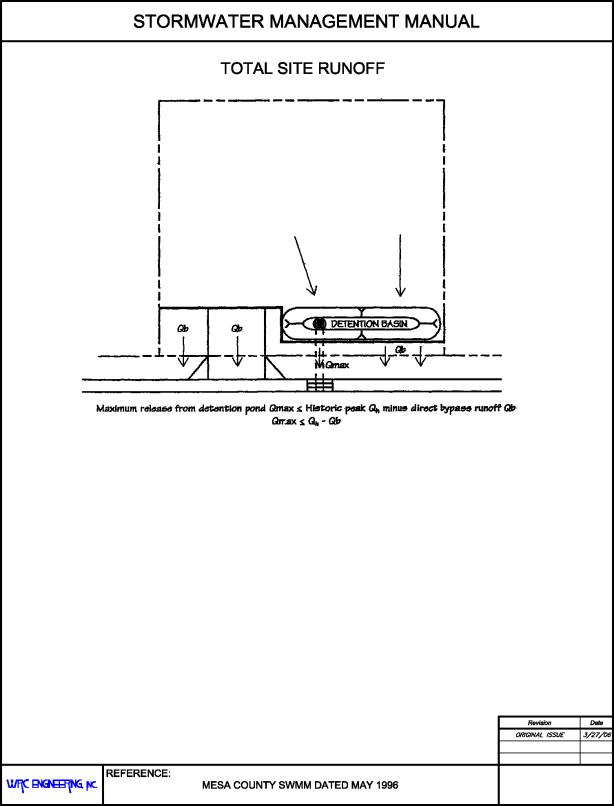
Peak runoff from a site may not be increased in the 10- and 100-year storms due to development. The site runoff may be a composite of detention/retention basin release/overflow and direct runoff, both of which must be considered. If direct runoff is allowed from the site, the sum of the direct runoff plus the release from the detention basin must not exceed the historic rate. This is depicted in Figure 28.56.090 and discussed further in GJMC 28.56.240.
(Res. 40-08 (§ 1406.1), 3-19-08)
28.56.100 Geometric requirements.
For proper function and safety considerations, geometric requirements shall be as shown on Figure 28.56.100.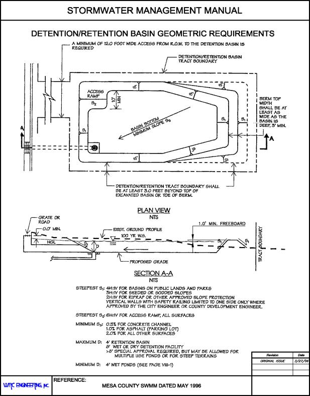
(Res. 40-08 (§ 1406.2), 3-19-08)
28.56.110 Dry basin bottom drainage.
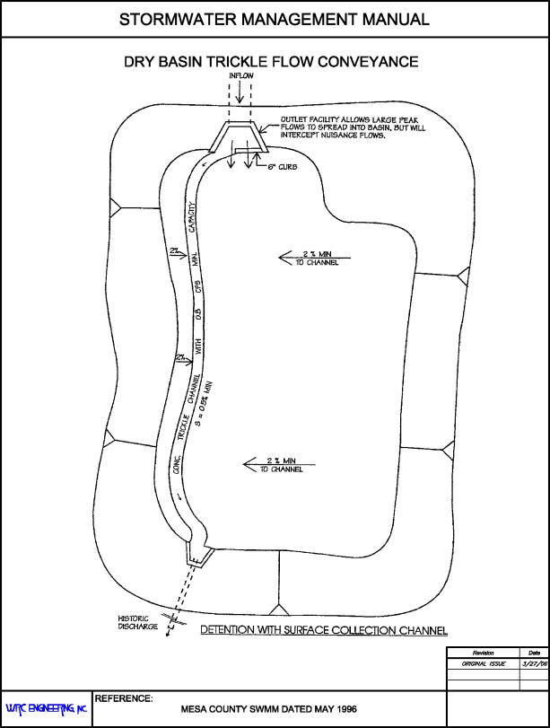
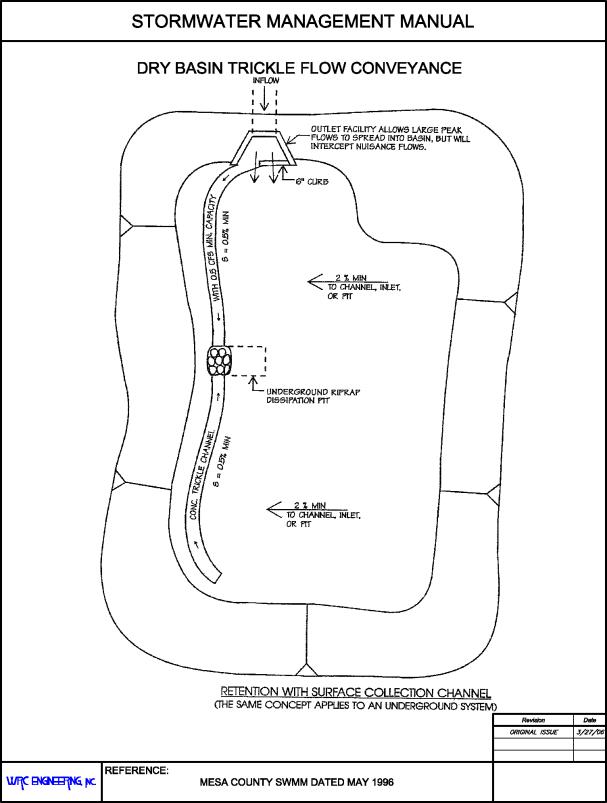
Most drainage conveyance systems are designed to divert even minor nuisance flows to stormwater storage facilities. For dry basins, this can present an aesthetic and maintenance problem. Conveyance facilities to a dry basin shall be capable of transporting flow to the outlet facility rather than causing a soggy bog condition that cannot be properly maintained. Facilities conveying trickle or nuisance flows, such as from irrigation sprinklers, shall be adequate to convey at least 0.5 cfs. Reference is made to Figures 28.56.110(a) and 28.56.110(b).
The outlet facility for a retention basin would be a dry well or riprap filled dissipation pit. For a detention basin, the nuisance flows shall be conveyed to the basin outlet.
(Res. 40-08 (§ 1406.3), 3-19-08)
28.56.120 Accessibility and maintenance.
All reservoirs or ponds which serve more than a single lot or site must be provided with a detention/retention tract dedicated for maintenance access. Maintenance of required volume and inflow and outflow works is necessary for the facility to function as required. Dedicated rights-of-way and/or easements must be provided as required in GJMC 28.16.020(b).
(Res. 40-08 (§ 1406.4), 3-19-08)
28.56.130 Calculating storage volume available.
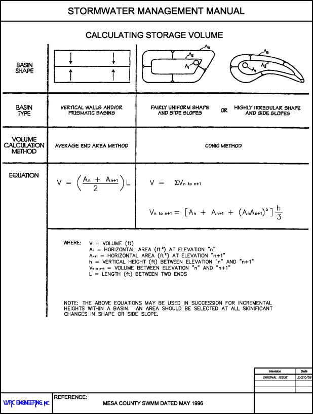
Storage volume shall be calculated by the methods shown prescribed in Figure 28.56.130.
(Res. 40-08 (§ 1406.5), 3-19-08)
28.56.140 Groundcover and landscaping.
After final grading, the slopes and bottom of each detention and retention basin shall be protected from erosion by seeding and mulching, sodding or other approved groundcover and shall be in accordance with jurisdictional specifications.
The planting of trees and shrubs on the slopes of stormwater basins is also encouraged. Temporary and/or permanent irrigation systems shall be provided as required for the type of groundcover and landscape installed and approved.
(Res. 40-08 (§ 1406.6), 3-19-08)
28.56.150 Freeboard requirements.
The minimum required freeboard for open space detention/retention facilities is 1.0 foot above the computed 100-year water surface elevation.
(Res. 40-08 (§ 1406.7), 3-19-08)
28.56.160 State Engineer’s Office.
Any dam constructed for the purpose of storing water, with a surface area, volume, or dam height as specified in § 37-87-105, C.R.S., as amended, shall require the approval of the plans by the State Engineer’s Office. All detention and retention storage areas shall be designed and constructed in accordance with these criteria. Those facilities subject to State statutes shall be designed and constructed in accordance with the criteria of the State.
(Res. 40-08 (§ 1406.8), 3-19-08)
28.56.170 Embankment protection.
Whenever a detention pond uses an embankment to contain water, the embankment shall be protected from catastrophic failure due to overtopping. Overtopping can occur when the pond outlets become obstructed or when a larger than 100-year storm occurs. Failure protection for the embankment may be provided in the form of a buried heavy riprap layer on the entire downstream face of the embankment or a separate emergency spillway having a minimum capacity of twice the maximum release rate for the 100-year storm. Structures shall not be permitted in the path of the emergency spillway or overflow. The invert of the emergency spillway shall be set equal to or above the 100-year water surface elevation.
(Res. 40-08 (§ 1406.9), 3-19-08)
28.56.180 Inlet and outlet design.
The outlet from the detention basin shall consist of a short (maximum 25 feet) length(s) of CAP or RCP with an 18-inch minimum diameter. Multiple pipe outlets may be required to control different design frequencies. The invert of the lowest outlet pipe shall be set at the lowest point in the detention pond or at the top of the minimum pool, if present. The outlet pipe(s) shall discharge into a standard manhole or into a drainageway with proper erosion protection for the proposed structure. If an orifice plate is required to control the release rates, the plate(s) shall be hinged to open into the detention pipes to facilitate back flushing of the outlet pipe(s).
Inlet to the detention pipes can be by way of surface inlets and/or by a local private storm sewer system.
(Res. 40-08 (§ 1406.10), 3-19-08)
28.56.190 Off-site flows.
It is rarely the case that a new development comprises an entire drainage basin. Instead, developments are most often located within a larger drainage basin. This means that unless the new development is located at the very upstream edge of a drainage basin, it will most likely receive sheet flow, if not concentrated flow, from off-site areas. Developers must look not only at the new development but also at the surrounding topography to determine just how much off-site area drains to the new development site.
For drainage design of new developments, there are two considerations for accommodating off-site storm runoff. These are peak runoff rates from off-site areas and routing of off-site storm runoff relative to the new development.
(a) Peak Storm Runoff Rates.
(1) Undeveloped Off-Site Areas. Runoff rates from off-site areas that are undeveloped but have a comprehensive development plan (comp plan) in place will be calculated using imperviousness values in Table 28.28.020 for the land use or surface characteristic specified by the comp plan. Runoff rates from off-site areas that are undeveloped and do not have a comp plan in place will be calculated using an imperviousness of 45 percent as specified in Table 28.28.020 (or as specified by the local jurisdiction).
(2) Developed Off-Site Areas. Runoff rates from off-site areas that are developed should be determined by calculating the actual imperviousness of the area using approved drainage reports, aerial photography, and field investigations. If this information is not available, imperviousness shall be determined based on general land use or surface characteristic as shown in Table 28.28.020.
The reduction of peak runoff rates from detention shall only be assumed for developments that are confirmed to have detention facilities and shall be subject to approval by the local jurisdiction. The discharge rates from these detention facilities shall be assumed to be those rates approved in the final drainage report for each off-site upstream area having detention facilities.
(b) Routing of Off-Site Storm Runoff. There are two methods by which off-site flows can be routed relative to the new development. These are routing around the new development and routing through the new development.
(1) Routing Around the New Development. Ideally the new development will be graded so off-site storm runoff is routed around the development based on peak rates determined in subsection (a) of this section. If this method is chosen, off-site flows must be routed to their historic path immediately downstream of the new development. Concentrated flows draining to the development should be maintained as concentrated flows downstream of the development and sheet flows should be maintained as sheet flow.
(2) Routing Through the New Development. If the site cannot be graded to accommodate rerouting off-site flows, the development’s detention pond must be sized to account for any off-site flow that comes into the new development and drains to the new detention pond. It is possible that routing off-site runoff through the new detention pond will significantly alter the volume and outlet requirements of the new detention pond.
The effects of routing storm runoff from off-site areas through the new detention pond shall be determined by hydrograph routing methods. A hydrograph of the off-site area, assuming ultimate development conditions without detention, shall be generated to achieve a total volume of runoff. The developed condition hydrograph shall then be truncated at the allowable release rate and extended in time such that the total runoff volume is the same. This modified hydrograph is a reasonable representation of the ultimate development runoff that is routed through a detention pond within the off-site development.
The modified off-site hydrograph is then added to the developed conditions hydrograph for the new development (assuming no on-site detention). This composite hydrograph shall then be routed through the new detention pond to verify that the release rates from the new detention pond meet allowable release rates. In this instance, the allowable release rate is the sum of the allowable release rates from both the off-site area and the new development. The design of the detention pond may require iteration on the detention volume and outlet configuration to achieve the required results.
(Res. 40-08 (§ 1406.11), 3-19-08)
28.56.200 Retention.
Retention will only be considered on a case-by-case basis with the following minimum requirements:
(a) Retention basins must drain within 48 hours of all storm events up to the 100-year storm event, beginning either at the start of the storm or when runoff first reaches the basin. Total runoff volume shall be determined by calculating imperviousness then converting this to a curve number (CN) following the procedures in Chapter 28.28 GJMC. Using the CN, excess precipitation for the design storm is determined using procedures described in GJMC 28.28.070. The design storm shall be the 24-hour precipitation amount of 2.01 inches multiplied by a factor of 1.5.
(b) The design of the retention basin must be supported by vertical hydraulic conductivity data for subsurface soil and/or rock obtained via an appropriate engineering test such as a tri-axial cell test, a permeameter test, or a vertical conductivity aquifer test conducted by a qualified geotechnical engineer familiar with the Mesa County soils and geology. Test data shall then be used in an appropriate calculation to determine the required size of the retention basin and the time required for complete infiltration of the 100-year storm event. One of the following models shall be used to demonstrate the design meets all criteria:
(1) Hydrus-2D (U.S. Dept. of Agriculture, Agricultural Research Service).
(2) SEEP/W (GeoSlope International, Inc.).
(3) Equivalent model (upon approval of local jurisdiction).
(c) When using vertical hydraulic conductivity data in these calculations, a saturated K-value shall only be used when it has been demonstrated that the infiltration media over the entire length of the infiltration path are saturated. If the infiltration path is characterized by unsaturated conditions, a partially saturated K-value shall be used for infiltration calculations.
(d) Measures that minimize sediment from entering and clogging the pond surface shall be implemented. These include pre-sediment basins and/or frequent sediment removal. Depth of storage shall be minimized and surface area shall be maximized for infiltration purposes. The wetted sides of the pond shall not be included in the area used to calculate infiltration releases.
(e) An emergency overflow from the retention area shall be provided with a minimum capacity of the 100-year peak inflow rate. The overflow path shall be carefully selected and analyzed for capacity and downstream impact. The overflow shall be located at the maximum retention volume water surface. A minimum of 1.0 foot of freeboard shall be provided above the maximum retention volume water surface.
(f) An operation maintenance plan shall be developed and be part of the development agreement that includes monitoring and reporting requirements and penalties for noncompliance. This plan may include pumping to meet the drain time requirements and should consider that there may be power outages during a major storm.
(Res. 40-08 (§ 1406.12), 3-19-08)
28.56.210 Hydrologic design methods and criteria.
The hydrologic design of detention facilities is based on the type of facility (regional vs. local) and the method used to estimate the runoff (HEC-1 vs. the rational method). If HEC-1 is used, a full hydrograph is available for traditional storage routing. If the rational method is used, only a peak flow rate is available. GJMC 28.52.220 through 28.56.250 discuss the procedures for these two methods. Note that the procedures used to calculate storm runoff are described in Chapter 28.28 GJMC.
(Res. 40-08 (§ 1407), 3-19-08)
28.56.220 HEC-1 method.
The HEC-1 method may be used to develop inflow hydrographs for hydrologic basins of any size, and may be used for both local and regional facilities. The inflow hydrographs shall be based on ultimate development conditions.
This program can calculate a hydrograph for any location in the hydrologic basin. The data input file must be structured so that the proposed detention basin site is a hydrograph-routing or hydrograph-combining point.
(a) Detention Basin Outflow Limitations. The controlled outlet capacity has direct influence on the required size of the basin. The outflow limitation can be based on either the existing undeveloped peak flow from the hydrologic basin or on limitations in the capacity of the downstream conveyance system (based on a hydrologic analysis of local conditions). The outflow limitation for local facilities is stated in GJMC 28.16.090. The design maximum outlet capacity of a regional facility must be coordinated with the local jurisdiction.
(b) Hydrologic Calculation Method. After the inflow hydrograph has been calculated and the outflow limits have been determined, the required storage volume can be estimated. Separate methods for calculating required storage are used depending on the method used to estimate the inflow hydrograph.
In order to calculate the required storage volume at a particular detention basin site, the following information must be available or prepared:
(1) Inflow hydrograph;
(2) Outlet capacity limitation;
(3) Proposed outlet discharge versus elevation data for the proposed basin site;
(4) Proposed storage vs. elevation data for the proposed basin site;
(5) Proposed drain time for the proposed basin site.
(c) The HEC-1 computer program can be used to determine the required storage volume and outflow limitation based on a reservoir routing procedure. Initial estimates of outlet size are made and the program is run. The output is reviewed and changes are made to the outlet configuration as needed until the desired degree of flood peak attenuation and acceptable drain time is achieved.
(Res. 40-08 (§ 1407.1), 3-19-08)
28.56.230 Rational method.
The minimum required volume shall be determined using the HEC-1 method or the following equations. These empirical equations were developed as part of the UDFCD hydrology research program and modified to reflect rainfall conditions in Mesa County. The equations are based on a computer modeling study and represent average conditions.
One of the most difficult aspects of storm drainage is obtaining consistent results between various methods for estimating detention requirements. These equations provide consistent and more effective approaches to the sizing of on-site detention ponds. The equations presented in this section may be used for hydrologic basins with a total area of less than 160 acres, per the rational method restrictions set forth in GJMC 28.28.100(c). The use of these equations in the design of regional detention facilities must be approved by Mesa County or the applicable local jurisdiction.
(a) Minimum Detention Volumes.![]()
For the 100-year,![]()
For the 10-year,![]()
Where:
|
V |
= |
required volume for the 100- or 10-year storm (acre-feet) |
|
P |
= |
Developed basin imperviousness (percent) |
|
A |
= |
Tributary area (acres) |
|
X |
= |
Mesa County and the other local jurisdictions adjustment factor per Table 28.56.230(a) |
|
Ultimate Development Percent Imperviousness |
X100 |
X10 |
|---|---|---|
|
< 50% |
0.42 |
0.26 |
|
≥ 50% |
0.48 |
0.38 |
(b) Allowable Release Rates. The maximum release rates at the ponding depths corresponding to the 10- and 100-year volumes are as follows:
|
Control Frequency |
Soil Group |
||
|---|---|---|---|
|
A |
B |
C |
|
|
10-year |
0.05 |
0.09 |
0.12 |
|
100-year |
0.25 |
0.43 |
0.50 |
The predominant soil group for the total basin area tributary to the detention pond shall be used for determining the allowable release rate. Information on the soils in Mesa County can be found in published SCS soil surveys.
(Res. 40-08 (§ 1407.2), 3-19-08)
28.56.240 Compensating detention analysis.
(a) If any storm runoff will be discharged from the property without first being routed through a detention pond, on-site detention facilities are to be designed using the compensating detention procedure. The total of all undetained area shall not exceed five percent or 5,000 square feet, whichever is less.
(b) Compensating detention is based on the following assumptions:
(1) The 10- and 100-year peak discharge from the property from detained and undetained area when added together will be no greater than allowable discharge. Therefore, the more undetained release of storm runoff from the site, the less the detention pond is permitted to release, which requires proportionally larger detention volume.
(2) Regardless of the method used, the volume of the detention pond must be adjusted to result in reduced discharge rates. For the HEC-1 method, the detention volume is determined using actual runoff hydrographs and storage routing based on the outlet configuration. For the rational method, the increase in volume is accomplished by simply computing the volume based on the entire property area, not just the area tributary to the detention pond. This is a reasonable assumption given the five percent area or 5,000 square feet size limitation on undetained area.
(c) The compensating detention procedure is given in six steps below. The following procedure applies to both the HEC-1 and rational method methods for determining detention volumes, except as specifically noted otherwise.
(1) Step 1. If the undetained area is less than five percent of the total project area or 5,000 square feet, whichever is less, continue. If not, then the undetained area must either be reduced in size or the site layout revised to be in compliance with the SWMM.
(2) Step 2. Determine the allowable release rate for the 10- and 100-year flood events based on the pre-project site conditions using the entire site area. See Table 28.56.230(b).
(3) Step 3. Determine the post-project runoff rates for the 10- and 100-year floods for the undetained area only.
(4) Step 4. Determine the adjusted allowable release rates by subtracting the runoff rates from the post-project, undetained area from the allowable release rates in Step 2.
(5) Step 5. Determine minimum required 100-year and 10-year storage volumes for the area tributary to the detention pond. If using the rational method, the storage volume is determined using the equations in GJMC 28.56.230 based on the entire project area, not just the area tributary to the detention pond.
(6) Step 6. Determine the final outlet configuration that results in the adjusted allowable release rates at the computed detention volumes for the entire site.
(Res. 40-08 (§ 1407.3), 3-19-08)
28.56.250 Over-detention analysis.
Over-detention is defined as detaining developed conditions peak flows to the point that release rates are lower than pre-developed conditions. Over-detention is sometimes required to meet capacity limitations of downstream drainage facilities. Specific over-detention requirements are identified in basin-wide or watershed master plans or by the local jurisdiction within which the detention pond is proposed.
Over-detention requirements are unique for each basin or watershed and are often based on a detailed hydrologic investigation using hydrograph methods to generate peak flows and route the flows through the drainage system. Simplified detention volume and release rate methods are not appropriate, and over-detention volume and release rate requirements shall be determined using a hydrograph analysis in accordance with the SWMM requirements.
(Res. 40-08 (§ 1407.4), 3-19-08)
28.56.260 Hydraulic design of outlet works.
Hydraulic design data for sizing of detention facilities outlet works is as follows:
(a) Weir Flow. The general form of the equation for horizontal crested weirs is:
|
|
(28.56-5) |
Where:
|
Q |
= |
discharge (cfs) |
|
C |
= |
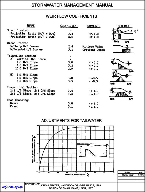
weir coefficient (see Table 28.56.260) |
|
L |
= |
horizontal length (feet) |
|
H |
= |
total energy head (feet) |
Another common weir is the v-notch, whose equation is as follows:
|
|
(28.56-6) |
Where:
|
θ |
= |
angle of the notch at the apex (degrees) |
When designing or evaluating weir flow, the effects of submergence must be considered. A single check on submergence can be made by comparing the tailwater to the headwater depth. The example calculation for a weir design on Figure 28.56.100 illustrates the submergence check.
(b) Orifice Flow. The equation governing the orifice opening and plate is the orifice flow equation:
|
|
(28.56-7) |
Where:
|
Q |
= |
Flow (cfs) |
|
Cd |
= |
Orifice coefficient |
|
A |
= |
Area (ft.2) |
|
g |
= |
Gravitational constant = 32.2 ft./sec2 |
|
h |
= |
Head on orifice measured from center of the opening (ft.) |
An orifice coefficient (Cd) value of 0.65 shall be used for sizing of squared edged orifice openings and plates.
(Res. 40-08 (§ 1408), 3-19-08)


