


Chapter 19.123
TOWN CENTER DESIGN STANDARDS
Sections:
Article I. Introduction
19.123.020 Applicability and compliance.
19.123.030 How the provisions of this chapter are applied.
Article II. Block Frontage Standards
19.123.050 How to use this chapter.
19.123.060 Block frontage designation maps.
19.123.070 About the transparency standards.
19.123.080 Storefront block frontage standards.
19.123.090 Storefront corner block frontage standards.
19.123.100 Landscaped block frontage standards.
19.123.110 Secondary block frontage standards.
19.123.120 Access corridor frontage standards.
19.123.130 Where properties front onto multiple streets.
19.123.140 Where properties have multiple designations along one frontage.
19.123.150 High-visibility street corners.
Article III. Site Planning
19.123.180 Side and rear yard setbacks.
19.123.190 Internal open space.
19.123.200 Internal pedestrian access and design.
19.123.210 Service areas and mechanical equipment.
Article IV. Building Design
19.123.240 Building massing and articulation.
19.123.260 Building materials.
19.123.270 Blank wall treatment.
Article I. Introduction
19.123.010 Purpose.
This chapter is authorized by the City Council as a major implementation tool of the Mountlake Terrace Comprehensive Plan. Overall, this chapter intends to:
A. Provide clear objectives for the planning and design of development projects in the Town Center and other applicable mixed-use areas.
B. Preserve and protect the public health, safety, and welfare of the citizens of Mountlake Terrace.
C. Ensure that new multifamily, mixed-use, and commercial development is of high quality and appropriate to Mountlake Terrace’s character and context.
D. Promote increased pedestrian, bicycling, and transit use in commercial and multifamily areas.
E. Enhance the livability of residential developments.
F. Increase awareness of design considerations among the citizens of Mountlake Terrace.
G. Maintain and enhance property values within Mountlake Terrace. (Ord. 2755 § 3 (Exh. B), 2019).
19.123.020 Applicability and compliance.
A. The design provisions in this chapter apply to all new development within the Town Center and TCR zone, including, but not limited to, building additions and site improvements. Exception: Additions to single-household dwellings are exempt from this chapter.
B. Relationship to Other Codes and Documents. Where provisions of this chapter conflict with provisions in any other section of the Mountlake Terrace Municipal Code (MTMC), this chapter prevails unless otherwise noted.
C. For building additions, remodels, and site improvements, two different thresholds have been established to determine how the standards herein are applied to such projects.
1. Level I improvements include all exterior remodels, building additions, and/or site improvements that affect the exterior appearance of the building/site and/or cumulatively increase the gross floor area on a site by up to 50 percent within three years of the date of permit issuance. The requirement for such improvements is only that the proposed improvements meet the standards and do not lead to further nonconformance with the standards.
For example, if a property owner decides to replace a building facade’s siding, then the siding must meet the applicable exterior building material standards, but elements such as building articulation would not be required.
2. Level II improvements include all improvements that cumulatively increase the gross floor area on a site by 50 percent or more within three years of the date of permit issuance. Such developments must conform to all applicable standards, except in a case where there are multiple buildings on one site, and only one building is being enlarged. In that scenario, improvements to the additional buildings are not required, but conformance with all other standards apply. (Ord. 2755 § 3 (Exh. B), 2019).
19.123.030 How the provisions of this chapter are applied.
Most sections within this chapter herein include the following elements:
A. Purpose statements, which are overarching objectives.
B. Standards use words such as “must” and “is/are required,” signifying required actions.
C. Guidelines use words such as “should” or “is/are recommended,” signifying voluntary measures.
D. Departures are provided for specific standards. They allow alternative designs provided the reviewing authority determines the design meets the purpose of the standards and guidelines and other applicable criteria. See MTMC 19.110.260 for related procedures associated with departures.
E. This chapter contains some specific standards that are easily quantifiable, while others provide a level of discretion in how they are complied with. In the latter case, the applicant must demonstrate to the director, in writing, how the project meets the purpose of the standard or standards. (Ord. 2755 § 3 (Exh. B), 2019).
Article II. Block Frontage Standards
19.123.040 Purpose.
A. To achieve the envisioned character of Mountlake Terrace Town Center as set forth in the goals and policies of the Town Center Subarea Plan and other applicable mixed-use areas.
B. To enhance pedestrian environments by emphasizing activated ground-level block frontage designs for commercial, mixed-use, and multifamily developments.
C. To minimize potential negative impacts of driveways and off-street parking facilities on the streetscape.
D. To promote good visibility between buildings and the street for security for pedestrians and to create a more welcoming and interesting streetscape. (Ord. 2755 § 3 (Exh. B), 2019).
19.123.050 How to use this chapter.
Site orientation standards for individual properties depend on the block frontage designated for that location. The following steps will help in using this chapter:
A. Go to the map in MTMC 19.123.060 to find the property and the block frontage type designation. For development that fronts onto multiple streets, see provisions in MTMC 19.123.140.
B. Go to the appropriate code section in this chapter for the standards for applicable block frontage type designation. Table 19.123.050 includes a summary of key block frontage types.
|
|
Permitted Frontage |
Details |
|---|---|---|
|
Storefront |
|
• No new ground-level parking adjacent to the street. • Special transparency, weather protection, and entry requirements. • Minimum commercial space height and depth. • No ground floor residential uses except for live/work units on select Storefront designated blocks where the storefront space meets height and depth standards. |
|
Secondary |
Storefront or Landscape Frontages Allowed |
• Ground-level parking must not be visible from the street. • Landscaping to soften facades of non-storefronts and buffer parking areas. • Minimum facade transparency requirements per use and setback. |
|
Landscape |
|
• Ground-level parking must not be visible from the street. • Landscaping to soften facades and buffer parking areas. • Minimum facade transparency requirements per use and setback. |
(Ord. 2755 § 3 (Exh. B), 2019).
19.123.060 Block frontage designation maps.
The block frontage designations established by this chapter are maintained under the direction of the director. All notations, references, and other information shown have the same force and effect as if fully described in this title.
Note that these block frontage designation maps are different than the streetscape designation map in Figure 19.50.080. Block frontage designations and standards regulate the development frontages, which includes the building and associated site development that occurs within the property boundary. The streetscape designations and standards set forth in MTMC 19.50.080 regulate the design of sidewalks and planting strips within the right-of-way. In some cases, the streetscape standards call for expanded sidewalks that extend beyond the property line. Also note that the streetscape standards sometimes vary on the type of block frontage design.
Figure 19.123.060
Map 1: Mountlake Terrace Town Center block frontage designations map.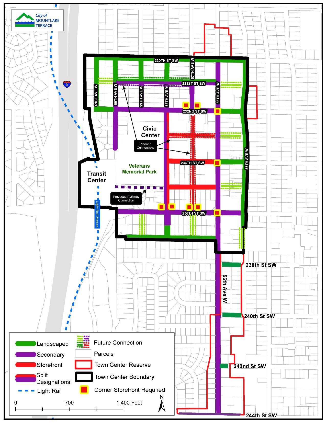
(Ord. 2755 § 3 (Exh. B), 2019).
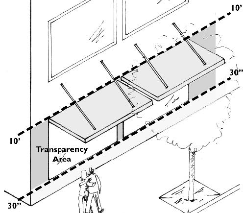
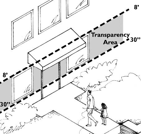
19.123.070 About the transparency standards.
All block frontage designations contain distinct minimum facade transparency standards. The purposes of these standards are to maintain “eyes on the street” for safety and create welcoming pedestrian environments. Table 19.123.070 below includes details in how they are measured.
|
Transparency Area |
||
|
Storefront |
Ground floor nonresidential and nonstorefront |
Residential buildings and residential portions of mixed-use buildings |
|
|
|
|
|
The transparency area is on the ground floor between 30" and 10' above sidewalk grade |
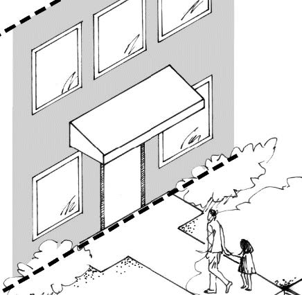
The transparency area is between 30" and 8' above grade |
All vertical surfaces of the facade are used in the calculations |
|
Other Transparency Provisions |
||
|
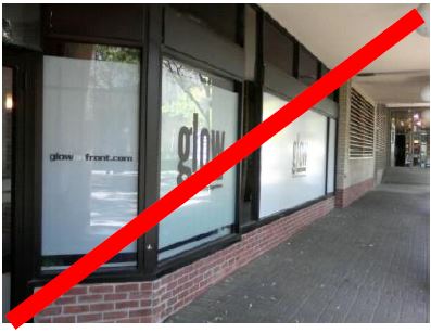
Windows must be transparent Ground-level window area for storefronts and other nonresidential uses that is covered, frosted, or perforated in any manner that obscures visibility into the building must not count as transparent window area. Also, mirrored glass and highly reflective or darkly tinted windows must not be counted as transparent windows. |
Covered windows |
Perforated sign |
|
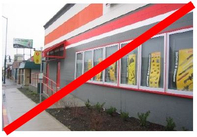
Display windows and parking garages Display windows may be used for up to 25% of nonresidential transparency requirements (except for ground-level storefront-designated block frontages on 57th Ave W and 233rd Street SW) provided they are at least 30" deep to allow changeable displays and the interior wall is nonstructural so it can be removed if the windows are not used for display. Tack-on display cases as shown in the far right example do not qualify as transparent window area. For parking garages (where allowed by block frontage standards), the left image illustrates how such a structure can meet (and not meet) the applicable transparency standards. |
Integrated display windows |
Tack-on display cases |
|
Parking garage with windows |
Parking garage without windows |
|


(Ord. 2755 § 3 (Exh. B), 2019).
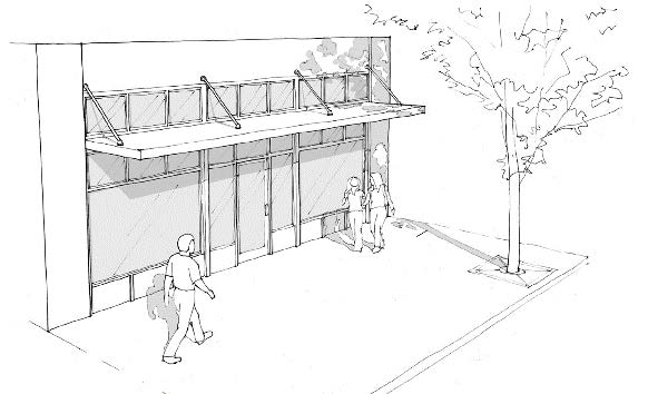
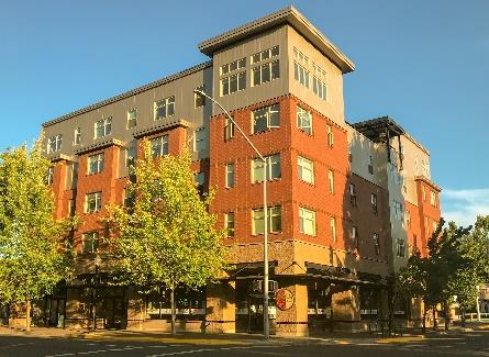
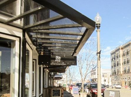
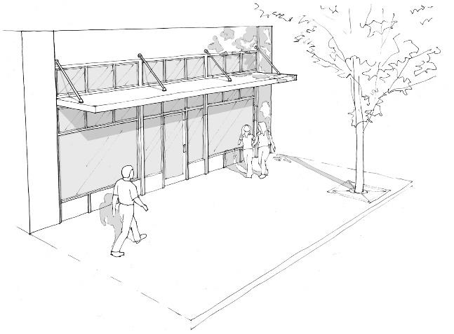
19.123.080 Storefront block frontage standards.
A. Purpose. Storefront block frontages are the most vibrant and active shopping and dining areas within Mountlake Terrace. Blocks designated as storefront block frontages include continuous storefronts placed along the sidewalk edge with small-scale shops and many business entries.
Figure 19.123.080(A)
Storefront vision and key standards.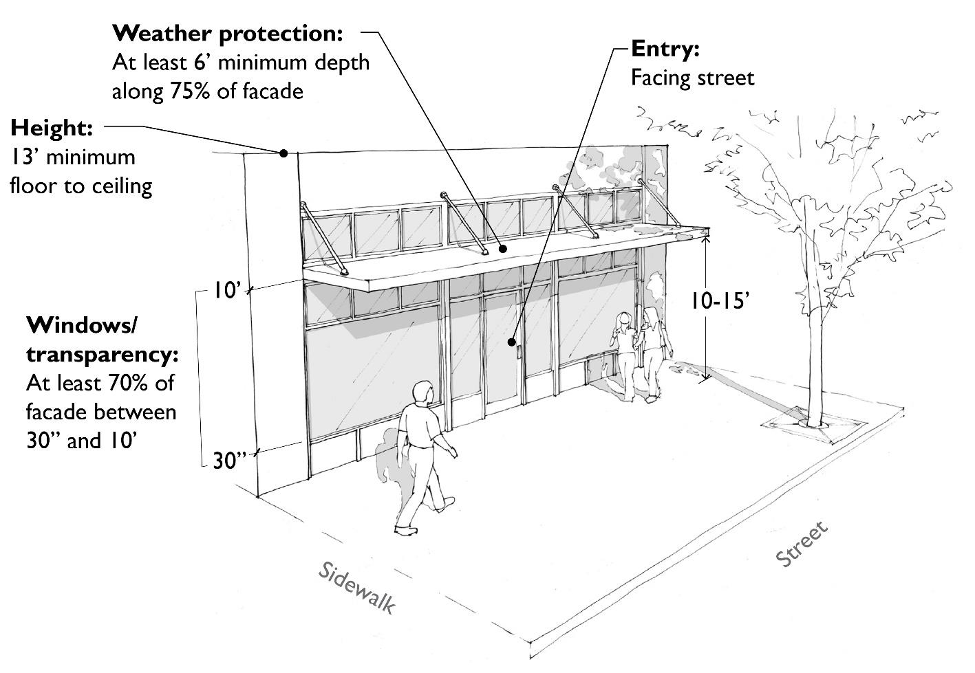
B. Standards. All development on sites with a storefront block frontage designation must comply with the standards in Table 19.123.080(B) below:
|
The ➲ symbol refers to departure opportunities in MTMC 19.123.080(C). |
||
|---|---|---|
|
Element |
Standards |
Additional Provisions and Examples |
|
Ground-level |
|
|
|
Land use |
MTMC 19.50.040 sets forth ground-level uses permitted on storefront block frontages. |
Lobbies and accessory uses associated with upper-floor professional-office and multi-household residential uses are allowed provided they are limited to 20% of all storefront block frontages and other storefront frontages. |
|
Floor to ceiling height |
13' minimum |
Applies to the minimum retail space depth. |
|
Retail space depth |
50' minimum on 57th Ave W and 233rd Street SW and 30' minimum elsewhere (applies to new buildings only). ➲ |
|
|
Building placement |
Buildings must be placed at the back edge of the required sidewalk. Additional setbacks are allowed for a widened sidewalk or pedestrian-oriented space (MTMC 19.123.190(D)). |
Corner storefront building example. |
|
Building entrances |
Primary building entrances must face the street. For corner buildings, primary entrances for ground-level building corner uses may face either street or the street corner. |
|
|
Facade transparency |
At least 70% of the transparency area. ➲ |
|
|
Weather protection |
Weather protection over the sidewalk is required along at least 75% of the storefront facade, and it must be a minimum of 6' deep and have 10' to 15' of vertical clearance. ➲ Weather protection must not interfere with street trees, street lights, street signs, or extend beyond the edge of the sidewalk. |
|
|
Parking location |
New ground-level (surface or structured) parking adjacent to the street is prohibited. Parking may be placed below, above, and/or behind storefronts. ➲ |
|
|
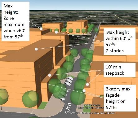
SPECIAL FOR STOREFRONT BLOCK FRONTAGES ALONG 57TH AVENUE WEST |
||
|
Height Stepbacks |
• Lower floors: Maximum building facade height of three stories. • Stepback minimum (after first, second or third floors): 10'. • Upper floors: Maximum building height within 60' of 57th Avenue W: Seven stories or 80' (whichever is less). • Maximum building height when more than 60' from 57th Avenue W: See MTMC 19.50.050 for standards applicable to the subject zone. |
|
C. Departure Criteria. Departures from the standards in Table 19.123.090(B) that feature the ➲ symbol will be considered per MTMC 19.110.260 provided the alternative proposal meets the purpose of the standards and the following criteria:
1. Retail Space Depth. Departures from this standard are not allowed for storefronts adjacent to 57th Street W and 233rd Street SW. Elsewhere, reduced depths on up to 25 percent of the applicable block frontage will be considered where the applicant can successfully demonstrate the proposed alternative design and configuration of the space is viable for a variety of permitted retail uses.
2. Facade Transparency. Departures for facade transparency in the transparency area may be reduced to a minimum of 40 percent for block-frontages other than 57th Avenue W and 233rd Street SW if the facade design between ground-level windows provides visual interest to the pedestrian and mitigates the impacts of blank walls.
3. Weather Protection. The reduced extent (to no less than 50 percent of block frontages) or width of weather-protection features (to no less than four feet in width) will be considered provided the designs are proportional to architectural features of the building and building design trade-offs (elements that clearly go beyond minimum building design standards in this chapter) meet the purpose of the standards. (Ord. 2755 § 3 (Exh. B), 2019).
19.123.090 Storefront corner block frontage standards.
All development on sites with a storefront corner block frontage designation must comply with the standards in Table 19.123.080(B) above, except that the storefront block frontage standards must apply to storefront building elevations at least 30 feet (horizontally) from the corner of the building and the entire length of the building that’s sited up to the edge of the sidewalk (as a storefront). For required building stepbacks on 57th Avenue W on the north side of 232nd Street SW, the subject stepback provisions apply only to the first 30 feet of 57th Avenue W block frontage north of 232nd Street SW.
Figure 19.123.090
Storefront corner block frontage example.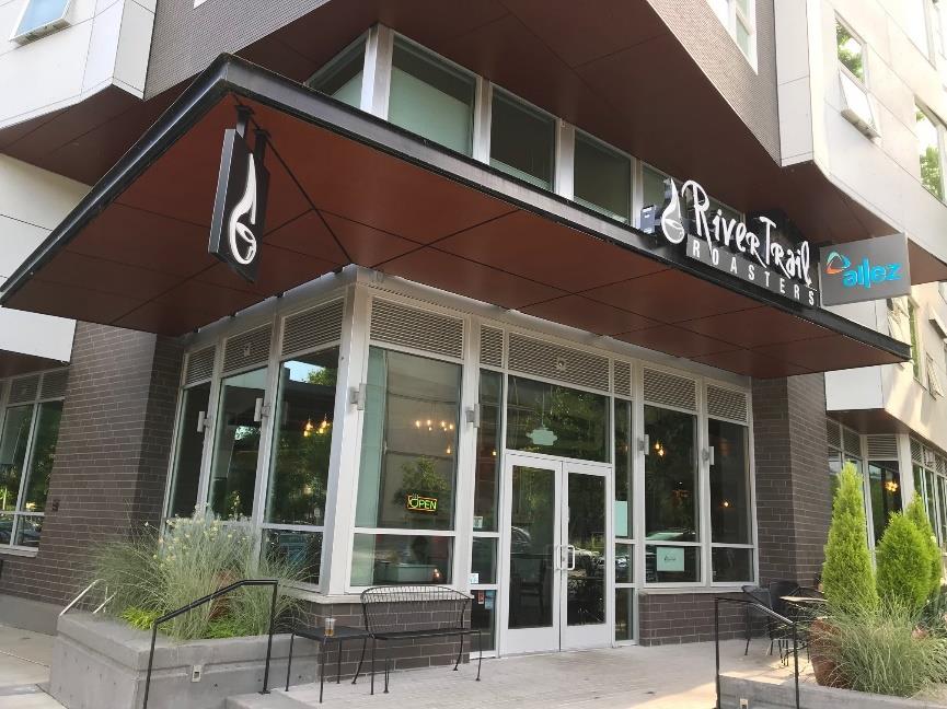
(Ord. 2755 § 3 (Exh. B), 2019).
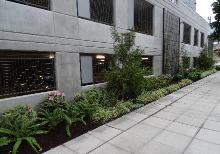
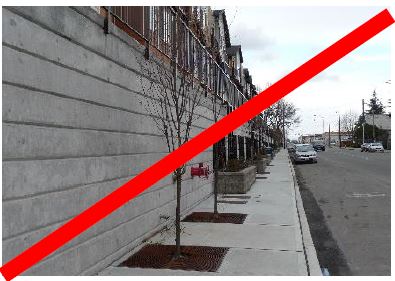
19.123.100 Landscaped block frontage standards.
A. Purpose. Landscaped block frontages emphasize landscaped street setbacks, clear pedestrian connections between the building and the sidewalk, and minimized surface parking lots along the frontages.
Figure 19.123.100(A)
Landscaped frontage vision and key standards.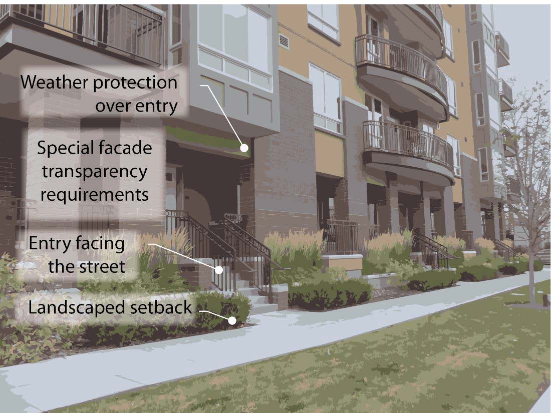
B. Standards. All development on sites containing a landscaped block frontage designation must comply with the standards in Table 19.123.100(B) below.
|
The ➲ symbol refers to departure opportunities in MTMC 19.123.100(C). |
||
|---|---|---|
|
Element |
Standards |
Additional Provisions and Examples |
|
Ground-level |
|
|
|
Land use |
MTMC 19.50.040 sets forth permitted land uses. |
|
|
Building placement |
10' minimum setbacks are required, or greater where specified for the applicable zone in MTMC Title 19. ➲ |
|
|
Building entrances |
Building entries must face the street or a pedestrian-oriented space (MTMC 19.123.190(D)) that is adjacent to the street. |
Landscaped frontage example meeting setback, entry, weather protection, and transparency standards. |
|
Facade transparency |
For buildings with ground-level nonresidential uses, at least 40% of the transparency area. ➲ For buildings with ground-level residential uses, at least 20% of the facade. ➲ |
|
|
Weather protection |
Weather protection at least 3' deep must be provided over individual residential and commercial tenant entries and at least 5' deep for shared residential and professional office entries. |
|
|
Parking location |
Ground-level parking must not be visible from the street. Where parking is integrated at or near the ground-level, it must be set back and completely screened by landscaped berms (upper right example). The lower right example illustrates a prohibited design. |
|
|
Landscaping |
All areas between the sidewalk and the building must be landscaped, except for pathways, porches, decks, and other areas meeting the definition of pedestrian-oriented space (MTMC 19.123.190(D)). Landscaped areas must contain Types I, II, or IV landscaping (as defined in MTMC 19.130.240) and may incorporate rain gardens and other forms of stormwater management. |
|
C. Departure Criteria. Departures to the landscaped block frontage standards in Table 19.123.100(B) that feature the ➲ symbol will be considered per MTMC 19.110.260 provided the alternative proposal meets the purpose of the standards and the following criteria:
1. Building Placement. Reduced setbacks (down to a minimum of eight feet) will be considered where the ground floor is elevated a minimum average of 30 inches (required when the ground floor setback is less than 10 feet) and design treatments that create an effective transition between the public and private realm. For example, a stoop design or other similar treatments that utilize a low fence or retaining wall, and/or hedge along the sidewalk may provide an effective transition (see Figure 19.123.110(C) for examples).
2. Facade Transparency. Facade transparency in the transparency area may be reduced from the minimum by 50 percent if the facade design between ground-level windows provides visual interest to the pedestrian and mitigates the impacts of blank walls. (Ord. 2755 § 3 (Exh. B), 2019).
19.123.110 Secondary block frontage standards.
A. Purpose. Secondary block frontages allow flexibility to integrate either a storefront or a landscaped frontage in a pedestrian-friendly configuration.
|
Storefront Frontage |
|
Landscaped Frontage |
|
OR |

B. Standards. Development must conform to either storefront or landscaped block frontage standards and associated departure options and departure criteria as established above, with only the following modifications in Table 19.123.110(B) below:
|
The ➲ symbol refers to departure opportunities in MTMC 19.123.110(C). |
||
|---|---|---|
|
Element |
Standards |
Additional Provisions and Examples |
|
Building placement |
Buildings may be placed up to the sidewalk edge provided they meet storefront block frontage standards in MTMC 19.123.080 (this includes standards for ground-level, building placement, building entrances, facade transparency, and weather protection elements). |
The minimum setback for buildings that do not meet applicable storefront block frontage standards is 10’ or greater where specified for the applicable zone in MTMC Title 19. ➲ |
|
Facade transparency |
Storefront buildings are subject to storefront block frontage transparency standards above. For other building frontages, transparent windows must be provided along at least 15% of the entire building facade, plus: • Buildings designed with ground-floor nonresidential uses within 10' of sidewalk, must feature at least 40% transparency within the transparency area. ➲ • Buildings designed with ground floor nonresidential uses within 20' of sidewalk, must feature at least 25% transparency within the transparency area. ➲ |
|
C. Departure Criteria. Departures to the secondary block frontage standards in Table 19.123.110(B) that feature the ➲ symbol will be considered per MTMC 19.110.260 provided the alternative proposal meets the purpose of the standards and the following criteria:
1. Building Placement. Reduced setbacks (down to a minimum of five feet for buildings with ground floor residential uses and a minimum of two feet for other buildings) will be considered where the ground floor is elevated a minimum average of 30 inches (required when the ground floor setback is less than 10 feet) and design treatments create an effective transition between the public and private realm. For example, a stoop design or other similar treatments that utilize a low fence or retaining wall, and/or hedge along the sidewalk may provide an effective transition (see Figure 19.123.110(C) for examples).
2. Facade Transparency. Facade transparency in the transparency area may be reduced from the minimum by 50 percent if the facade design between ground-level windows provides visual interest to the pedestrian and mitigates the impacts of blank walls.
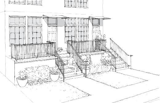
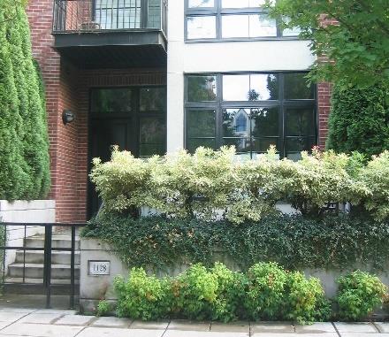
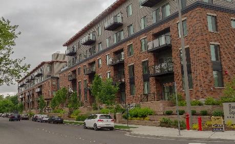
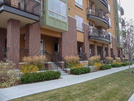
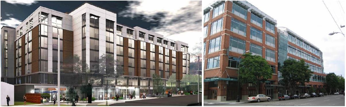
Figure 19.123.110(C)
Acceptable examples of possible setback departures.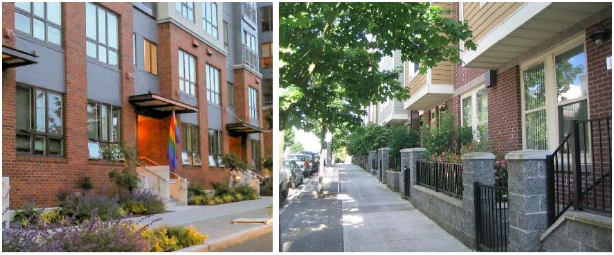
The apartment building (left image) includes a street setback of about six to eight feet and features a landscape planter, an elevated ground-level, and generous window transparency. The elevated stoop frontages (right image) is another acceptable reduced setback departure example. The combination of landscaping elements, facade transparency, low fencing, and facade materials and detailing help to create an effective transition between the public and private realm.
(Ord. 2755 § 3 (Exh. B), 2019).
19.123.120 Access corridor frontage standards.
A. Purpose. Access corridor frontage standards provide eyes on the pathway to create a safe and welcoming through-block connection while preserving the privacy of adjacent ground-level residential units.
B. Standards.
1. Building elevations facing an access corridor must feature at least 10 percent window transparency. ➲
2. Where ground-level residential uses are within five feet of a shared-lane or pathway, at least one of the following design features must be integrated to enhance the safety and privacy of adjacent residential units:
a. Windows must be placed at least six vertical-feet above the access corridor.
b. A combination of landscaping, planter walls, and/or elevated ground floor (at least one foot above access corridor grade) that meet the purpose of the standards.
3. Where nonresidential ground-level uses abut an access corridor, at least 25 percent of the applicable building elevation between four and eight feet above the ground-floor surface elevation must be transparent. ➲
Figure 19.123.120(A)
Access corridor example illustrating shared pedestrian and vehicular access.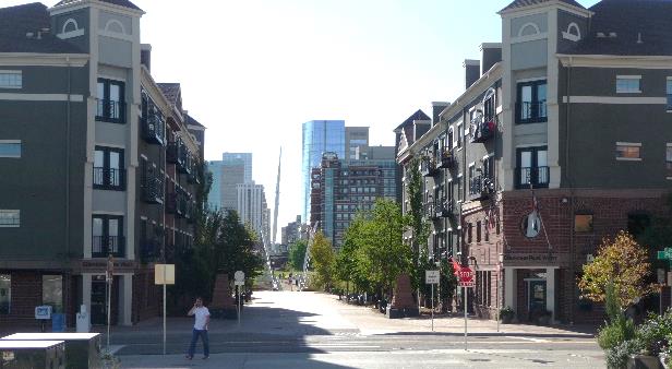
Figure 19.123.120(B)
Pedestrian access corridor examples.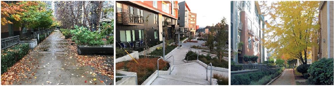
(Ord. 2755 § 3 (Exh. B), 2019).
19.123.130 Where properties front onto multiple streets.
Where a property fronts onto more than one street, each building frontage must comply with the standards for the block frontage upon which it fronts, with the following clarifications:
A. Where a conflict exists between frontage standards, the director will apply the standards of a block frontage pursuant to the following order of preference:
1. Storefront;
2. Secondary; then
3. Landscaped.
Subsections B through E of this section clarify how the order of preference works for particular frontage elements.
B. Building Location. For corner sites with landscaped block frontage on one street and storefront or secondary on another, a storefront frontage may wrap around the corner (on the landscaped block frontage side) for up to a half-block width or no more than 120 feet (whichever is less).
C. Entrances. For corner sites, entrances on both streets are encouraged, but only one entrance is required. For corner sites with frontage on a storefront block frontage on one side, an entrance must be placed on the storefront block frontage side or facing the corner. For corner sites with a mix of designations that do not include a storefront block frontage, the entry must be placed on the order of preference identified above.
Departures may be considered provided the location and design of the entry and block frontage treatments are compatible with the character of the area and enhance the character of the street.
D. Transparency. For corner sites, at least one block frontage must meet the applicable transparency standards, based on the order of preference above. For the second block frontage, the director may approve a reduction in the minimum amount of transparency by 50 percent. For street corners with the same designations on both frontages, buildings must employ the full transparency on the dominant frontage (based on the frontage width or established neighborhood pattern). Exception: No reductions in the minimum required window transparency are allowed on 57th Ave W and 233rd Street SW where designated as a storefront.
Figure 19.123.130
Clarifying block frontage standards on street corners.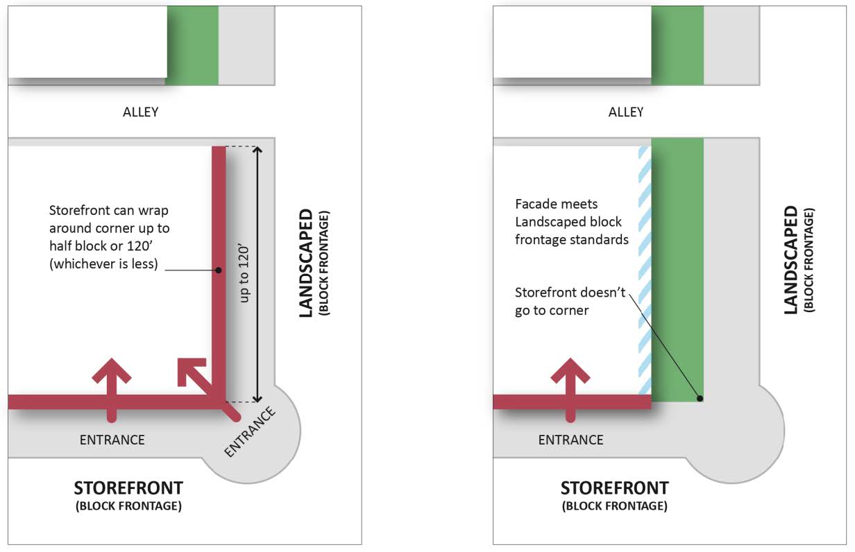
In the left example, the entrance may be placed along the storefront block frontage and/or directly on the corner.
(Ord. 2755 § 3 (Exh. B), 2019).
19.123.140 Where properties have multiple designations along one frontage.
Where an individual property has a frontage with multiple block frontage designations, the following standards apply:
A. Storefront and Any Other Block Frontage Designation. Storefront block frontage designation applies.
B. Secondary and Landscaped Block Frontage Designation. Secondary block frontage designation applies. (Ord. 2755 § 3 (Exh. B), 2019).
19.123.150 High-visibility street corners.
A. Description/Purpose. The high visibility street corner requirements apply to those sites designated as such on Figure 19.123.150(A). The purpose is to accentuate designated street corners with high visibility to the public.
Figure 19.123.150(A)
High visibility street corners.
B. Standards. At least one of the following special features must be included (Figure 19.123.150(B) below illustrates acceptable examples):
1. Corner plaza.
2. Cropped building corner with a special entry feature.
3. Decorative use of building materials at the corner.
4. Distinctive facade articulation.
5. Sculptural architectural element.
6. Other decorative elements that meet the purpose of the standards.
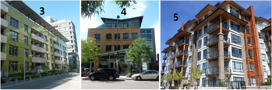
Figure 19.123.150(B)
Acceptable high visibility street corner examples.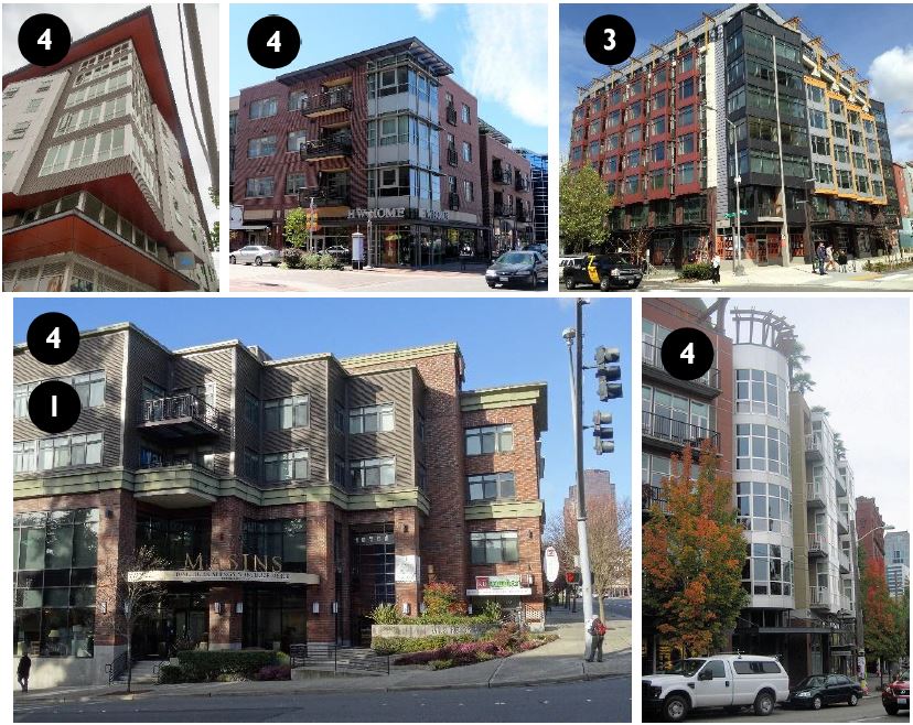
All of the buildings above integrate distinctive articulation features (4). The bottom left example also integrates a corner plaza (1).
(Ord. 2755 § 3 (Exh. B), 2019).
Article III. Site Planning
19.123.170 Purpose.
A. To promote thoughtful layout of buildings, parking areas, and circulation, service, landscaping, and amenity elements.
B. Enhance Mountlake Terrace’s visual character.
C. Promote compatibility between developments and uses.
D. Enhance the function of developments. (Ord. 2755 § 3 (Exh. B), 2019).
19.123.180 Side and rear yard setbacks.
A. Purpose.
1. To promote the functional and visual compatibility between developments, particularly between zones of different intensity.
2. To protect the privacy of residents on adjacent properties.
B. Side and Rear Setback Standards. Table 19.50.050 sets forth a range of minimum side and rear yard setbacks in all TC and TC-R zones between zero and 15 feet. The provisions below clarify specific setback requirements:
1. Zero side and rear yard setbacks are allowed for buildings up to six stories in height, except within and adjacent to the TC-R zone, where developments integrated windowless fire walls that meet the design provisions of MTMC 19.123.270(D).
|
Min. Setback |
Applicability/Standard |
|---|---|
|
0' |
For windowless firewalls up to 6 stories in height. Provision does not apply to the development within or abutting the TC-R zone. All firewalls must meet the design provisions of MTMC 19.123.270(D). |
|
5' |
Minimum setback except: • Where zero setbacks are allowed (window-less firewalls as described above) • Where setbacks greater than 5' are required per provisions below |
|
>5' |
In all sites abutting residential zones – see subsection (C) of this section. |
|
15' – 20' |
When required per subsection (E) of this section for light and air access and privacy along side and rear property lines. |
C. Special Setback/Building Height Standards for Sites Abutting Residential Zones. For sites abutting a residential zone, the side and rear yard setback must be the same as the applicable residential zoning district, up to the maximum height limit of the applicable residential zoning district, above which the minimum side yard setback must increase at a 45-degree angle inward up to the maximum height of the applicable TC zoning district. See Figure 19.123.180(C) for an illustration.
Figure 19.123.180(C)
Illustrating minimum side and rear yard setbacks to an abutting residential zoning district.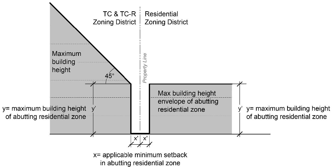
D. Balconies near Side and Rear Property Lines Adjacent to Property in Any Residential Zone. Balconies and rooftop decks above the ground floor within 15 horizontal feet of a side property line abutting a residentially zoned property must feature a railing system that is at least 50 percent opaque. Specifically, 50 percent of the area below the top edge of the railing must be a sight-obscuring structure.
Departures to this standard will be allowed if the balcony will not cause visual or privacy impacts due to its location, orientation, design or other consideration.
Figure 19.123.180(D)
Privacy standards for balconies within 15 feet of side or rear property lines.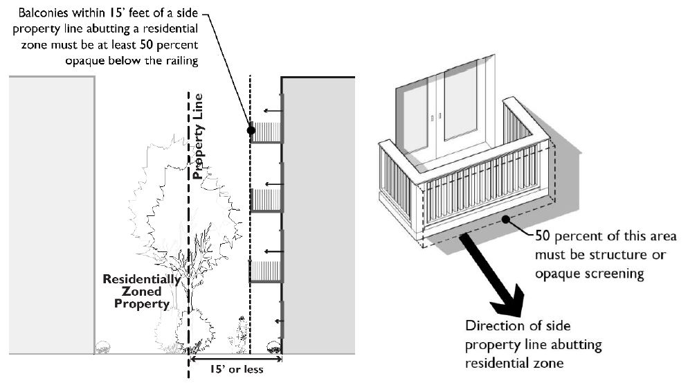
E. Light and Air Access and Privacy near Interior Side and Rear Property Lines. Buildings or portions thereof containing multifamily dwelling units whose only solar access (windows) is from the applicable side or rear of the building (facing towards the side or rear property line) must be set back from the applicable side or rear property lines at least 15 feet. See Figure 19.123.180(E). For such building elevations taller than four stories, floors above the fourth-floor must be set back at least 20 feet from the applicable side or rear property lines. Note: These standards do not apply to side or rear property lines where adjacent to a street, access corridor, or easement where no building may be developed.
Departures will be allowed where it is determined that the proposed design will not create a compatibility problem in the near and long term based on the unique site context.
Figure 19.123.180(E)
Light/air access and privacy standards for multifamily residential buildings along side and rear property lines.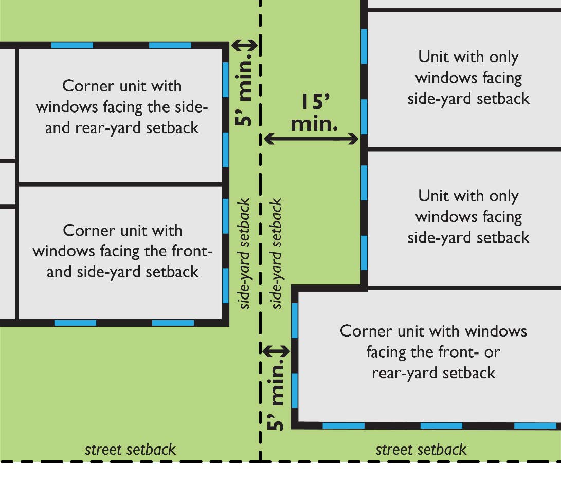
Note that the minimum setbacks noted above only apply to buildings (and portions thereof) featuring the stated characteristics.
F. Upper-Level Setbacks. Buildings over six stories are subject to the following minimum side and rear yard setbacks:
1. Fifteen feet for floors above the sixth floor.
2. Twenty feet for floors above the eighth floor.
Departures will be allowed where it is determined that the proposed design will not create a compatibility problem in the near and long term based on the unique site context. (Ord. 2755 § 3 (Exh. B), 2019).
19.123.190 Internal open space.
A. Purpose.
1. To create useable space that is suitable for leisure or recreational activities for residents.
2. To create open space that contributes to the residential setting.
3. To provide plazas that attract shoppers to commercial areas.
4. To provide plazas and other pedestrian oriented spaces in commercial areas that enhance the employees’ and public’s opportunity for active and passive activities, such as dining, resting, people watching, and recreational activities.
5. To enhance the development character and attractiveness of commercial development.
B. Usable Residential Open Space.
1. All multifamily development, including multifamily portions of mixed-use development, must provide minimum usable open space equal to 100 square feet per dwelling unit for studio and one-bedroom dwellings and 150 square feet per dwelling unit for dwellings with two or more bedrooms. The required open space may be provided in a combination of ways:
a. Shared Open Space. All of the required open space may be in the form of shared open space available to all residents and meeting the requirements of subsection (B)(2) of this section.
b. Ground-Level Individual Outdoor Space. All of the required open space for a unit may be provided by ground-level outdoor space that is adjacent and directly accessible to the subject unit. Such open spaces must be:
i. Outdoor spaces may be located in the front, side, or rear yard provided they are generally level, feature no dimension less than 10 feet, and enclosed by a fence and/or hedge at least 32 inches in height to qualify.
Departures will be considered for this provision.
ii. Private porches may qualify as outdoor space provided they are at least 36 square-feet in area, with no dimension less than six feet.
Individual ground-level open space that is in excess of minimum requirements must not be used in the calculations for determining the minimum usable open space requirements for other units in the development.
c. Balconies. Up to 25 percent of the required open space may be provided by private balconies provided such spaces are at least 32 square feet in area, with no dimension less than four feet (not including railings), to provide a space usable for human activity.
d. Common Indoor Recreation Areas. For mixed-use buildings up to 50 percent of the required open space may be provided by common indoor recreation areas meeting the following conditions:
i. The space must meet ADA standards and must be located in a visible area, such as near an entrance, lobby, or high traffic corridors.
ii. The space must be designed specifically to serve interior recreational functions and not merely be leftover unrentable space used to meet the open space requirement. Such space must include amenities and design elements that will encourage use by residents.
e. Shared Roof Decks. For multifamily buildings, up to 50 percent of the required open space may be provided by shared roof decks located on the top of buildings which are available to all residents and meet the requirements below. For mixed-use buildings, 100 percent of the required open space may be provided by shared roof decks. Design requirements:
i. Space must feature hard surfacing, provide amenities such as seating areas, landscaping, and/or other features that encourage use.
ii. Space must integrate landscaping elements that enhance the character of the space and encourage its use.
iii. Space must incorporate features that provide for the safety of residents, such as enclosures, railings, and appropriate lighting levels.
Figure 19.123.190(B)(1)(e)
Rooftop deck examples.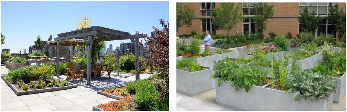
2. Shared Open Space Design Requirements. Shared open space can include landscaped courtyards or decks, entrance plazas, gardens with pathways, children’s play areas, pools, and water features provided they are accessible to all residents of the development. Accessible areas used for stormwater retention, infiltration, or other multipurpose recreational and/or green spaces that meet the design criteria herein may qualify as shared open space.
Special requirements for shared open spaces include the following:
a. Shared open space must be located in centralized areas that are visible from units within the development.
b. Required setback areas must not count as shared open space unless the design of the space meets the standards herein.
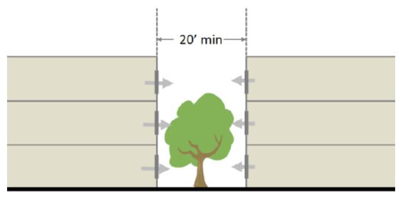
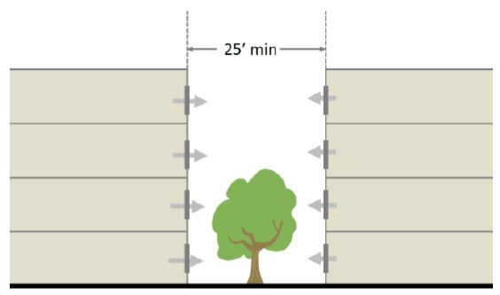
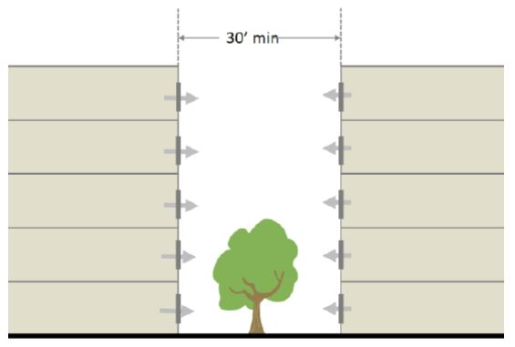
c. Shared open space must feature no dimension less than 15 feet in order to provide functional leisure or recreational activity. Wider minimum dimensions are required perpendicular to building elevations containing windows of dwelling units whose only solar access is from the applicable building wall. Specifically:
i. Twenty feet minimum for such elevations up to three stories tall.
ii. Twenty-five feet minimum for such elevations four stories tall.
iii. Thirty feet minimum for such elevations five or more stories tall.
d. Shared open space must feature paths or walkable lawns, landscaping, seating, lighting, and play structures, sports courts, or other pedestrian amenities to make the area more functional and enjoyable for a range of users.
e. Shared open space must be separated from ground-level windows, streets, service areas and parking lots with landscaping, fencing, and/or other acceptable treatments that enhance safety and privacy for both the shared open space and dwelling units.
f. When possible, the space should be oriented to receive sunlight, facing east, west or preferably south.
g. Stairways and service elements located within or on the edge of shared open space must not be included in the open space calculations.
h. Shared porches may qualify as shared open space, provided they are at least eight feet in depth and 96 square feet in total area.
i. The space must be accessible to all residents of the development.
Figure 19.123.190(B)(2)
Shared open space examples.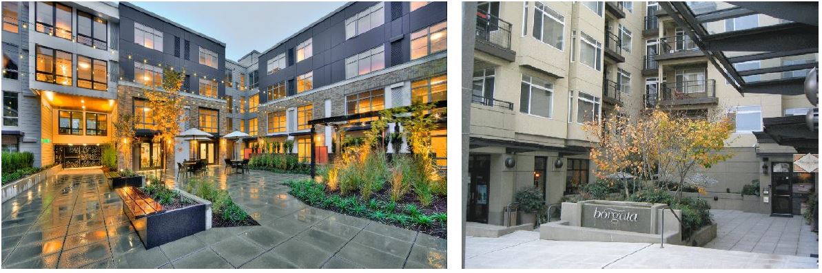
The upper left example is a courtyard over a parking deck. Notice the transition elements between the courtyard and adjacent residential units. The upper right courtyard is shared by ground-level commercial uses and apartments above.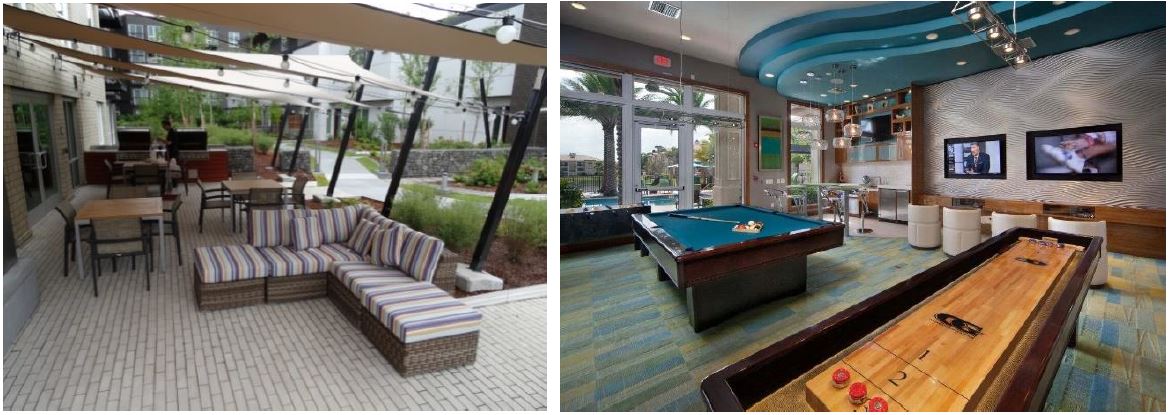
The left image above includes a covered gathering space with outdoor grills adjacent to a landscaped commons with a central pathway. The right image is an example of shared indoor recreation space.
|
|
20 feet minimum for such elevations up to three-stories tall. |
|
|
25 feet minimum for such elevations four-stories tall. |
|
|
30 feet minimum for such elevations five or more stories tall |
C. Usable Commercial Open Space. New developments on designated storefront block-frontages and other developments with non-residential uses with more than 10,000 square feet of gross floor area must provide 400 square feet of pedestrian-oriented space for each 100 lineal feet of block frontage. Pedestrian-oriented space located adjacent to street corners may be counted for the frontages of both streets. Portions of sidewalks that are wider than the minimum required in MTMC 19.50.090 may be used to meet up to 50 percent of this requirement.
Departure: Pedestrian-oriented space area may be reduced by 50 percent if the director finds the project includes exceptional design features and elements that meet the purpose of the standards. This includes open spaces that feature a combination of design (site materials, amenities, and configuration) and location/context that clearly exceed typical plaza designs found in the region.
D. Pedestrian-Oriented Space Design Criteria. This subsection describes the requirements and desired characteristics of pedestrian oriented open space (which may be used to meet the requirements of subsection C of this section).
1. Required Pedestrian-Oriented Open Space Features.
a. Visual and pedestrian access into the site from a street, private access road, or nonvehicular courtyard.
b. Paved walking surfaces of either concrete or approved unit paving. Form-in-place pervious concrete paving is allowed.
c. Lighting must conform to MTMC 19.120.030.
d. The spaces must be located in or adjacent to areas with significant pedestrian traffic to provide interest and security, such as adjacent to or visible from a building entry.
e. At least two feet of seating area (a bench or ledge at least 16 inches deep and appropriate seating height) or one individual seat per 60 square feet of plaza area or open space.
f. Landscaping components that add visual interest and do not act as a visual barrier. This could include planting beds, raised planters, and/or potted plants.
2. Desirable Pedestrian-Oriented Open Space Features.
a. Pedestrian amenities, such as site furniture, artwork, drinking fountains, shade structures, kiosks, or other similar features.
b. Adjacent buildings with transparent windows and doors covering at least 50 percent of the facade between 30 inches and 10 feet above the ground-level.
c. Pedestrian weather protection, alcoves, seating, or other features along building edges to allow for outdoor gathering.
3. Features Prohibited within a Pedestrian-Oriented Open Space.
a. Asphalt pavement.
b. Adjacent service areas (e.g., trash areas, loading docks) that are not separated with landscaping, as required by MTMC 19.123.210.
c. Adjacent chain-link fences.
d. Adjacent “blank walls” without “blank wall treatment” (see MTMC 19.123.270).
e. Outdoor storage.
Figure 19.123.190(D)
Example of site development integrating pedestrian-oriented space.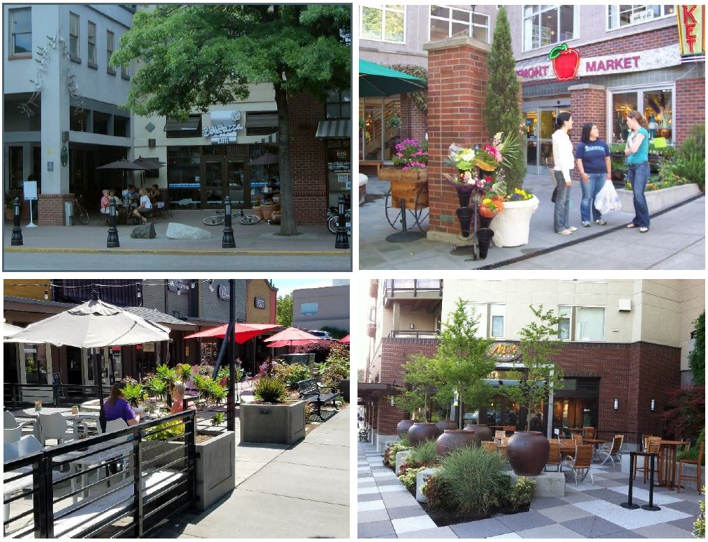
Figure 19.123.190(D)(1)
Example of a small pedestrian-oriented open space.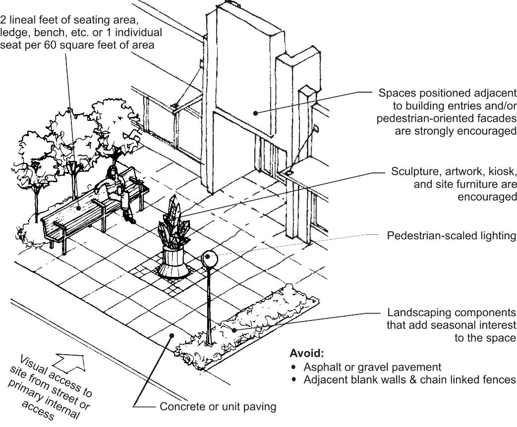
(Ord. 2755 § 3 (Exh. B), 2019).
19.123.200 Internal pedestrian access and design.
A. Purpose.
1. To improve the pedestrian and bicycling environment by making it easier, safer, and more comfortable to walk or ride among residences, to businesses, to the street sidewalk, to transit stops, through parking lots, to adjacent properties, and connections throughout the city.
2. To enhance access to on- and off-site open space areas and pedestrian/bicycle paths.
B. Access to Sidewalk. All buildings must feature pedestrian connections to a sidewalk per applicable block frontage standards in Article II of this chapter.
C. Internal Circulation.
1. For sites with multiple buildings, pedestrian paths connecting businesses and residential entries on the same development site must be provided. Routes that minimize walking distances must be utilized to the extent practical.
Departures will be allowed where steep slopes prevent a direct connection or where an indirect route would enhance the design and/or use of a common usable open space. See subsection D of this section for pathway design standards.
2. Sites with Residential Units. Provide direct pedestrian access between all ground-related unit entries and a public street or to a clearly marked pathway network or open space that has direct access to a public street. Residential developments must provide a pedestrian circulation network that connects all main entrances on the site to other areas of the site, such as:
a. Parking areas.
b. Recreational areas.
c. Common outdoor areas.
d. Any pedestrian amenities.
For townhouses or other residential units fronting the street, the sidewalk may be used to meet this standard. (Ord. 2755 § 3 (Exh. B), 2019).
19.123.210 Service areas and mechanical equipment.
A. Purpose.
1. To minimize adverse visual, odor, and noise impacts of mechanical equipment, utility cabinets and service areas at ground and roof levels.
2. To provide adequate, durable, well-maintained, and accessible service and equipment areas.
3. To protect residential uses and adjacent properties from impacts due to location and utilization of service areas.
B. Location of Ground-Related Service Areas and Mechanical Equipment.
1. Service areas (loading docks, trash dumpsters, compactors, recycling areas, electrical panels, and mechanical equipment areas) must be located for convenient service access while avoiding negative visual, auditory, olfactory, or physical impacts on the streetscape environment, pedestrian-oriented spaces, uses within the development, and adjacent residentially zoned properties.
The director may require evidence that such elements will not significantly impact neighboring properties or public areas. (For example, the director may require noise damping specifications for fans near residential zones.)
2. Exterior Loading Areas. Exterior loading areas for commercial uses must not be located within 20 feet of a residentially zoned property.
Departures may be allowed where such a restriction does not allow feasible development, and alternative design measures can successfully mitigate potential negative impacts. For example, areas and drives may be required by the reviewing authority to be separated from the residential lot by a masonry wall at least eight feet high.
3. Service areas must not be visible from the sidewalk and adjacent properties. Where the director finds that the only option for locating a service area is an area visible from a street, internal pathway or pedestrian area, or from an adjacent property, the area must be screened with structural and or landscaping screening measures provided in subsection C of this section and Chapter 19.130 MTMC.
4. Design for Safety. Other provisions of this section notwithstanding, service areas used by residents must be located to avoid entrapment areas and other conditions where personal security is potentially a problem. The director may require pedestrian-scaled lighting or other measures to enhance security.
5. Locate and/or shield noise producing mechanical equipment such as fans, heat pumps, etc, to minimize sounds and reduce impacts at property lines adjacent to residentially zoned properties.
6. Dumpster Storage Areas.
a. Dumpster storage areas must be provided for all nonresidential and multifamily development.
b. Dumpster storage areas must be on site and must not be located in the public right-of-way.
c. Dumpster storage areas must be sized to accommodate the minimum dumpster sizes (as required by the applicable utility provider) for garbage, recycling, and composting.
C. Screening of Ground-Related Service Areas and Mechanical Equipment. Service elements are encouraged to be integrated within the structure. Where they are not provided within the structure, the following standards apply:
1. Where screening of ground-level service areas is required (see subsection (B)(3) of this section), the following applies:
a. A structural enclosure must be constructed of masonry, heavy-gauge metal, or decayresistant material that is also used with the architecture of the main building. The reviewing authority may allow materials other than those used for the main building if the finishes are similar in color and texture or if the proposed enclosure materials are more durable than those for the main structure. The walls must be sufficient to provide full screening from the affected roadway, pedestrian areas or adjacent use. The enclosure may use overlapping walls to screen dumpsters and other materials (see Figure 19.123.210(D)).
b. Gates must be made of heavy-gauge, site-obscuring material. Chain link or chain link with slats is not an acceptable material for enclosures or gates.
c. Where the interior of a service enclosure is visible from surrounding streets, pathways, and buildings, an opaque or semi-opaque horizontal cover or screen must be used to mitigate unsightly views. The horizontal screen/cover should be integrated into the enclosure design (in terms of materials and/or design).
d. Collection points must be located and configured so that the enclosure gate swing does not obstruct pedestrian or vehicular traffic, or does not require that a hauling truck project into any public right-of-way. Ensure that screening elements allow for efficient service delivery and removal operations.
e. The service area must be paved.
2. The sides and rear of service enclosures must be screened with landscaping at least five feet wide in locations visible from the street, parking lots, and pathways to soften views of the screening element and add visual interest.
Departures to the provisions of subsections (C)(1) and (2) of this section will be considered per MTMC 19.110.260 provided the enclosure and landscaping treatment meet the purpose of the standards and add visual interest to site users.
3. Where loading docks are sited along block frontages (only allowed when no other reasonable options are available as determined by the director), they must be designed to minimize impacts on the pedestrian environment. Standards:
a. Configure loading docks/bays to minimize their frontage length along blocks.
b. Integrate architectural and/or landscaping design features to screen loading dock elements and add visual interest to pedestrians along adjacent sidewalks. See blank wall provisions of MTMC 19.123.270 for standards and examples.
D. Utility Meters, Electrical Conduit, and Other Service Utility Apparatus. These elements must be located and/or designed to minimize their visibility to the public. Project designers are strongly encouraged to coordinate with applicable service providers early in the design process to determine the best approach in meeting these standards. If such elements are mounted in a location visible from the street, pedestrian pathway, shared open space, or shared auto courtyards, they must be screened with vegetation and/or integrated into the building’s architecture.
Figure 19.123.210(D)
Utility meter location and screening – good and bad examples.
Place utility meters in less visible locations. The lower left example is successfully tucked away in a less visible location and screened by vegetation. The right image is poorly executed and would not be permitted in such visible locations (along the sidewalk). Such meters must be coordinated and better integrated with the architecture of the building.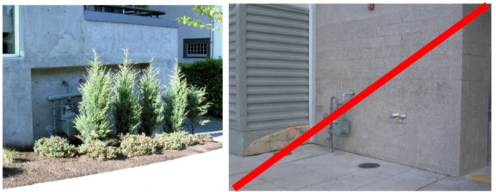
E. Location and Screening of Roof-Mounted Mechanical Equipment.
1. All rooftop mechanical equipment, including air conditioners, heaters, vents, and similar equipment must be effectively screened from public view both at grade and from nearby higher buildings with the exception of solar panels and roof-mounted wind turbines. Screening must be located so as not to interfere with operation of the equipment.
2. Rooftop mechanical equipment and associated screening features must be set back from the exterior building walls by at least 10 feet. Exceptions may be made where the screening element is designed to help meet one or more building design standards of Article IV of this chapter.
3. For rooftop equipment, all screening devices must be well integrated into the architectural design through such elements as parapet walls, false roofs, roof wells, clerestories, or equipment rooms. Screening walls or unit-mounted screening is allowed but less desirable. Wood must not be used for screens or enclosures. Louvered designs are acceptable if consistent with building design style. Perforated metal is not permitted.
4. The screening materials must be of material requiring minimal maintenance and must be as high as the equipment being screened.
5. Locate and/or shield noise producing mechanical equipment such as fans, heat pumps, etc., to minimize sounds and reduce impacts at property lines of adjacent properties.
Also see MTMC 19.123.250(F) for design provisions for flat rooftops.
Figure 19.123.210(E)
Examples of how to screen roof-mounted mechanical equipment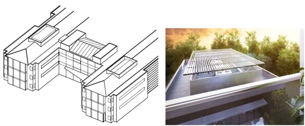
The left illustration shows how rooftop mechanical equipment can be located and screened effectively. The right images shows effective location and screening, including side walls and a trellis to screen views from taller surrounding buildings.
(Ord. 2755 § 3 (Exh. B), 2019).
Article IV. Building Design
19.123.220 Purpose.
This section provides direction for the design of buildings consistent with the goals and policies of the Mountlake Terrace Comprehensive Plan. See the individual “purpose” statements for each section in this chapter. (Ord. 2755 § 3 (Exh. B), 2019).
19.123.230 Applicability.
Public buildings may be exempted from building massing and articulation standards (see MTMC 19.123.240), building details standards (see MTMC 19.123.250), building materials provisions (see MTMC 19.123.260), and blank wall treatment standards (see MTMC 19.123.270) provided design treatments are integrated to meet the following objectives:
A. Enliven the pedestrian environment along the adjacent sidewalks.
B. Incorporate a prominent and inviting entry visible from the street.
C. Building design and materials should evoke a sense of permanence.
D. Site and building design stands out from the surrounding context as a distinct landmark and provides visual interest from all observable scales. (Ord. 2755 § 3 (Exh. B), 2019).
19.123.240 Building massing and articulation.
A. Purpose. To employ facade articulation techniques that reduce the perceived scale of large buildings and add visual interest from all observable scales.
B. Tower Design. The following standards apply to buildings over seven stories:
1. Tower Separation Standards. Towers (portions of buildings over seven stories) must maintain at least 40 feet of separation from other towers. Departures will be considered for towers constructed on the same site, provided the configuration and orientation of the towers maximize privacy and minimize skyline, skyview, and access to light impacts. Factors to consider in determining if a proposed departure meets the purpose include the extent of building area that doesn’t meet separation requirement, lot size and configuration, surrounding context, skyline views from a full range of observable views, and subject building uses.
2. Tower Form. Towers must employ original and distinctive form, including horizontal and vertically articulated components that provide depth, richness, and interest to the building from multiple vantage points. Simple box design for towers is prohibited. Example design treatments:
a. Round/sculpted forms.
b. Layered building forms.
c. Wall plane offsets and/or material changes that create shadows and relief.
d. Creative fenestration pattern changes.
Figure 19.123.240(B)
Tower design examples.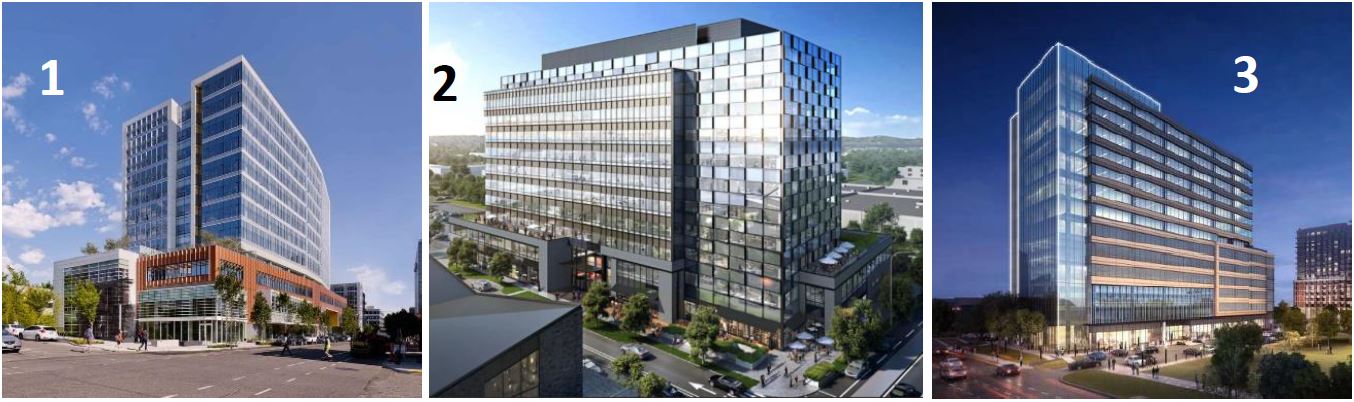
Building 1 includes substantial podium with a curved tower that includes vertical articulation on one side. Building 2 includes a number of massing offsets with changes in fenestration that lend interest and depth to the façade. Building 3 also uses a number of massing offsets and material/fenestration changes to add visual interest. All buildings have a strong ground-level emphasis.
C. Facade Articulation. All buildings under eight stories tall must include facade articulation features at maximum-specified intervals to create a human-scaled pattern. These standards apply to building elevations facing streets, parks, access corridors, and residential zones.
1. Maximum facade articulation intervals:
a. 57th Avenue W and 233rd Street SW: 30 feet.
b. Storefronts and other nonresidential frontages: 40 feet.
c. Residential frontages: The width of the dwelling units inside the building (e.g., if the units are 25 feet wide, the facade articulation must be 25 feet wide).
2. Articulation Features. At least three of the following articulation features must be employed for all buildings in compliance with the maximum-specified facade articulation intervals:
a. Use of a window fenestration pattern.
b. Use of weather protection features.
c. Use of vertical piers/columns (applies to all floors of the facade, excluding upper level stepbacks).
d. Change in roofline per subsection E of this section.
e. Change in building material and/or siding style (applies to all floors of the facade, excluding upper-level stepbacks).
f. Vertical elements such as a trellis with plants, green wall, art element that meet the purpose of the standard.
g. Providing vertical building modulation of at least 12 inches in depth if tied to a change in roofline per subsection E of this section or a change in building material, siding style, or color. Balconies may be used to qualify for this option if they are recessed or projected from the facade by at least 18 inches.
h. Other design techniques that effectively reinforce a pattern of articulated facades compatible with the building’s surrounding context.
Departures will be considered provided they meet the purpose of the standards and the design criteria below. For example, a departure may propose a design with only two articulation features instead of three and/or the articulation features exceed the maximum articulation interval.
Figure 19.123.240(C)(2)
Facade articulation examples.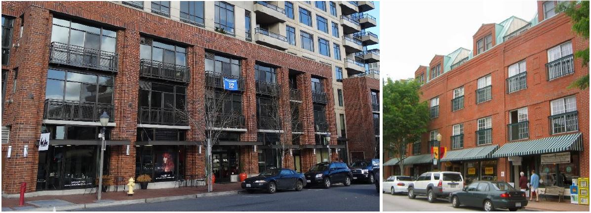
Both buildings use a combination of window patterns, weather protection features, and vertical piers to effectively articulate the facade.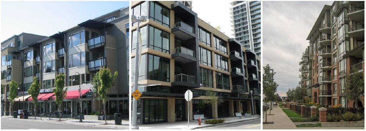
All three buildings above include a combination of window patterns and vertical building modulation. The left building uses recessed balconies, whereas the middle and right example use projecting balconies. The left and middle buildings also include weather protection features.
3. Departure Criteria Associated with Articulation Standards. Proposals must meet the purpose of the standards. The following criteria will be considered in determining whether the proposed articulation treatment meets the “purpose”:
a. Consider the type and width of the proposed articulation treatment and how effective it is in meeting the purpose given the building’s current and desired context (per Mountlake Terrace’s Town Center Subarea Plan).
b. Consider the applicable block-frontage designation. Secondary or landscaped block frontages warrant more flexibility than storefront block frontages.
c. Consider the size and width of the building. Smaller buildings (less than 120 feet wide) warrant greater flexibility than larger buildings.
d. Consider the quality of facade materials in concert with doors, windows, and other facade features and their ability to add visual interest to the street from a pedestrian scale and more distant observable scales.
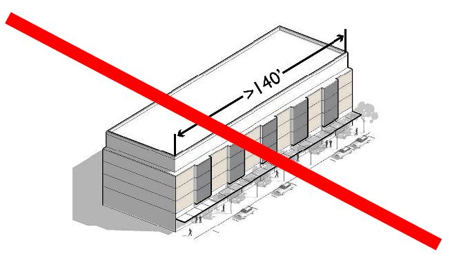
D. Maximum Facade Length. Building facades and other building elevations facing lower intensity zone edge must include at least one of the following features to break up the massing of the building and add visual interest. This standard applies to applicable building elevations longer than 140 feet.
1. Provide vertical building modulation at least six feet deep and 15 feet long. For multi-story buildings, the modulation must extend through at least one-half of the building floors.
2. Use of a contrasting vertical modulated design component featuring all of the following:
a. Utilizes a change in building materials that effectively contrast from the rest of the facade.
b. Component is modulated vertically from the rest of the facade by an average of six inches.
3. Facade employs building walls with contrasting articulation that make it appear like multiple distinct buildings. To qualify for this option, these contrasting facades must employ all of the following:
a. Different building materials and/or configuration of building materials.
b. Contrasting window design (sizes or configurations).
4. Departures to subsections (D)(1) through (3) of this section will be considered provided the design meets the purpose of the standards. Supplemental consideration for approving alternative designs:
a. Width of the Facade. The larger the facade, the more substantial articulation/ modulation features need to be.
b. Block Frontage Designation. Storefront designated block frontages warrant the most scrutiny.
c. The type of articulation treatment and how effective it is in meeting the purpose given the building’s context.
|
|
|
|
Less than 140' long: Meets standard |
More than 140' long: Does not meet standard |
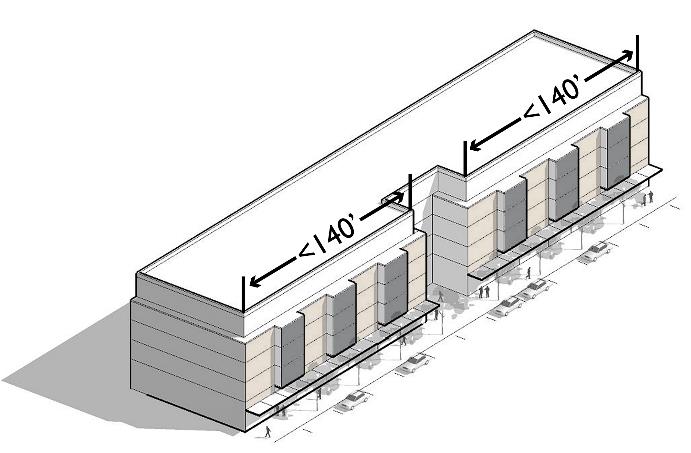
|
Building incorporates a courtyard along the facade (technique #1 noted above) to effectively break it up into smaller components: Meets standard. |
|
|
The left building uses technique # 1 (vertical building modulation at least six-feet deep and 15 feet wide). The right building uses technique #2 (contrasting vertical modulated design component) together with different window fenestration designs on each side. Both examples are effective in breaking up the perceived scale of the building and adding visual interest. |
|

E. Roofline Modulation. Roofline modulation is encouraged and it can be used as one of the facade articulation features in subsections C and D of this section. In order to qualify as an articulation feature, rooflines must employ one or more of the following:
1. For flat roofs or facades with horizontal eave, fascia, or parapet, the minimum vertical dimension of roofline modulation is the greater of two feet or 0.1 multiplied by the wall height (finish grade to top of the wall) when combined with vertical building modulation techniques described in subsections above. Otherwise, the minimum vertical dimension of roofline modulation is the greater of four feet or 0.2 multiplied by the wall height.
2. A pitched roofline or gabled roofline segment of at least 20 feet in width. Buildings with pitched roofs must include a minimum slope of 5:12 and feature modulated roofline components at the interval required per the applicable standard above.
3. A combination of the above.
Departures will be considered provided the roofline modulation design effectively reduces the perceived scale of the building and adds visual interest.
Figure 19.123.240(E)
Acceptable examples of roofline modulation.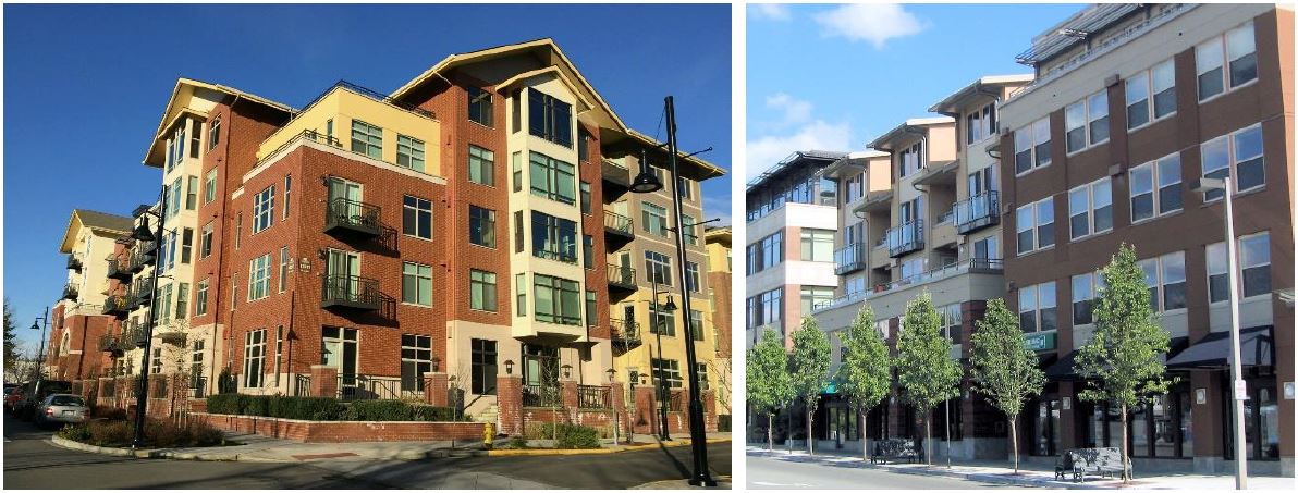
(Ord. 2755 § 3 (Exh. B), 2019).
19.123.250 Building details.
A. Purpose.
1. To encourage the incorporation of design details and small-scale elements into building facades that are attractive at a pedestrian scale.
2. To integrate window design that adds depth, richness, and visual interest to the facade.
B. Facade Details – Nonresidential and Mixed-Use Buildings. All building facades and other building elevations facing parks, pedestrian-oriented spaces, and containing primary building entrances must be enhanced with appropriate details. All new buildings must employ at least one detail element from each of the three categories below for each facade articulation interval (see MTMC 19.123.240(B)).
1. Window and/or entry treatment, such as:
a. Transom windows.
b. Roll-up windows/doors.
c. Recessed entry.
d. Decorative door.
e. Other decorative or specially designed window or entry treatment that meets the purpose of the standards.
Figure 19.123.250(B)(1)
Examples of decorative or specially designed windows and entries.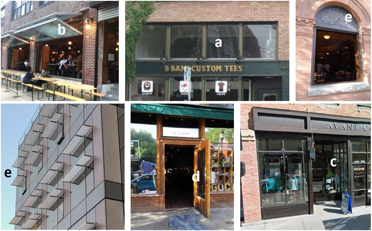
Examples of decorative or specially designed windows and entries. Upper left (b) = openable storefront window. Center top (a) = transom windows. Upper right (e) = openable window with decorative details. Lower left (e) = decorative window shades. Bottom middle (d) = Decorative door. Bottom right (c) = recessed entry.
2. Building elements and facade details, such as:
a. Custom-designed weather protection element such as a steel canopy, glass, or retractable awning. Custom-designed cloth awnings may be counted as a detail provided they are constructed of durable, high-quality material.
b. Decorative building-mounted light fixtures.
c. Bay windows, trellises, towers, and similar elements.
d. Other details or elements that meet the purpose of these standards.
Figure 19.123.250(B)(2)
Examples of attached elements that enhance the visual intrigue of the building.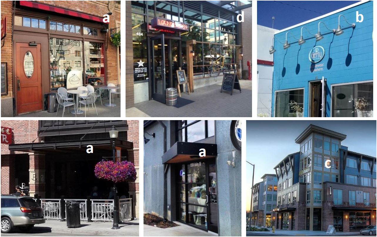
Examples of elements attached to facades that enhance the visual intrigue of the building. Upper left (a) = retractable awning. Top center (d) = custom hanging bike rack and repair station integrated as a storefront design element. Upper right (b) = decorative lighting fixtures. Lower left and middle (a) = custom decorative canopy. Lower right (c) decorative tower.
3. Building materials and other facade elements, such as:
a. Use of decorative building materials/use of building materials. Examples include decorative use of brick, tile, or stonework.
b. Decorative kick-plate, pilaster, base panel, or other similar feature.
c. Hand-crafted material, such as special wrought iron or carved wood.
d. Other details that meet the purpose of the standards.
Figure 19.123.250(B)(3)
Examples of building material details that enhance the visual intrigue of the building.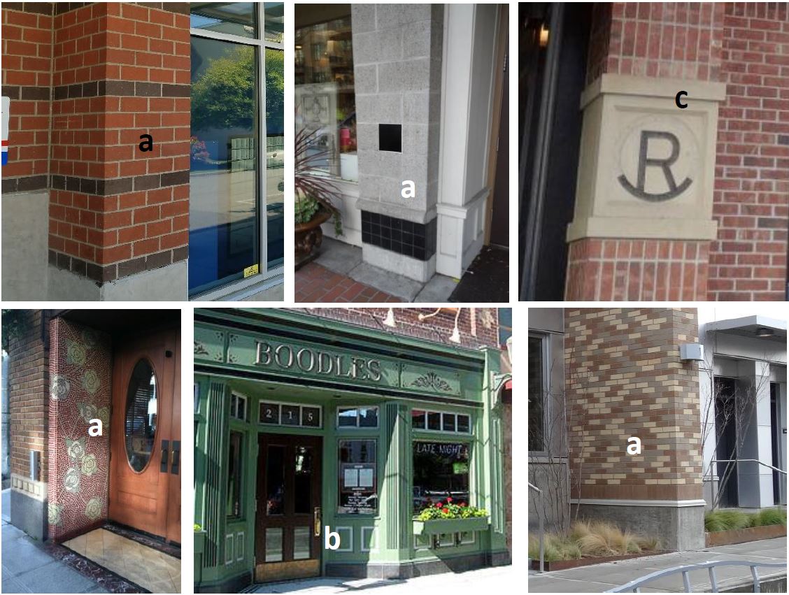
Examples of decorative surface materials. The letters match the detail options in subsection (B)(3) of this section.
Departures for facade detail standards of this subsection will be considered provided the facade (at the overall scale and at the individual articulation scale) meets the purpose of the standards.
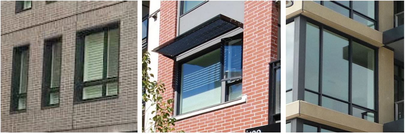
C. Window Design Standards.
1. All windows must be recessed by at least two inches from the facade to add depth and richness to the building. Other design treatments to windows that add depth, richness, and visual interest to the facade will be considered. Exemptions:
a. Storefront display windows.
b. Windows on buildings over seven stories in height provided such buildings comply with MTMC 19.123.240(B).
2. Highly reflective glass must not be used on more than 10 percent of a building facade or other building elevations facing parks and containing primary building entrances.
Figure 19.123.250(C)
Acceptable and unacceptable window design examples.
|
|
|
|
|
All but the lower middle image are recessed by at least two inches from the facade and add a sense of depth and richness to the facade. |
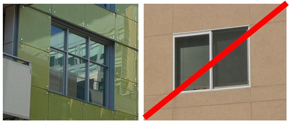
D. Cornice/Roofline Design. Buildings employing a flat roof must employ a distinctive roofline that effectively provides an identifiable “top” to the building. This could include a traditional cornice line or a contemporary interpretation of a traditional cornice line.
1. Such rooflines must be proportional to the size and scale of the building.
2. Understated cornice lines are permitted depending on the materials and design of the base and middle elements in reinforcing the base/middle/top configuration.
Figure 19.123.250(D) below illustrates acceptable and unacceptable examples.
Figure 19.123.250(D)
Examples of buildings employing confident and distinctive rooflines.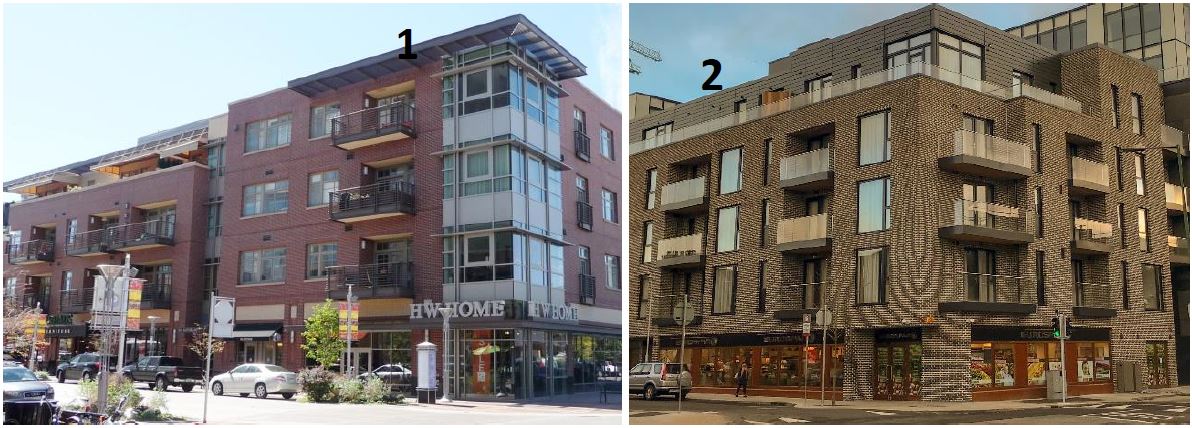
Building 1 uses a dramatic overhanging cornice at the corner. Building 2 uses a simple glass railing and an upper level building stepback. Building 3 uses a dramatic overhanging cornice line. Building 4 uses a “V” shaped roofline on its penthouse floor. Building 5 uses a highly articulated roofline with stepped overhangs.
Buildings 6 and 7 simply appear to end without any statement of confidence and do not meet the standard.
Rooftop solar units are permitted, provided the placement and design of units visible from the surrounding streetscape are carefully integrated into the overall design concept of the building.
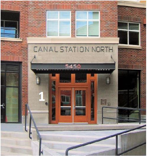
E. Articulated Building Entries. The primary building entrance for an office building, hotel, apartment building, public or community-based facility or other multi-story commercial building must be designed as a clearly defined and demarcated standout architectural feature of the building. Such entrances must be easily distinguishable from regular storefront entrances on the building. Such entries must be scaled proportional to the building. See Figure 19.123.250(E) below for good examples.
Figure 19.123.250(E)
Acceptable building entry examples.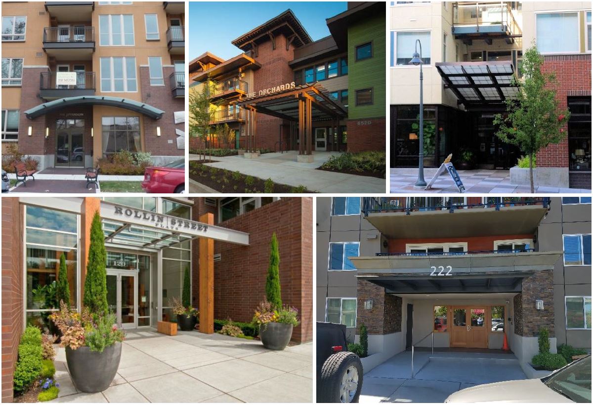
F. Flat Rooftop Design. All roofs must be designed as a fifth building elevation. This can be accomplished by exhibiting patterns of roofing colors and/or materials to add visual interest from surrounding development (current and future). Green roofs and rooftop decks are encouraged as a means to help comply with this standard.
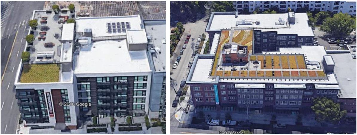
Figure 19.123.250(F)
Flat rooftop design examples.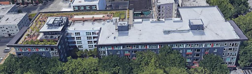
(Ord. 2755 § 3 (Exh. B), 2019).
19.123.260 Building materials.
A. Purpose.
1. To encourage the use of durable, high quality, and urban building materials that minimize maintenance cost and provide visual interest from all observable vantage points.
2. To promote the use of a distinctive mix of materials that helps to articulate facades and lends a sense of depth and richness to the buildings.
3. To place the highest priority on the first floor in the quality and detailing of materials at the pedestrian scale.
B. Special Conditions and Limitations for the Use of Certain Cladding Materials.
1. Concrete block (a.k.a. concrete masonry unit or CMU) may be used as a secondary cladding material (no more than one-third of total facade cladding) on all building facades and other building elevations facing parks, pedestrian-oriented spaces, and containing primary building entrances provided it is incorporated with other permitted materials.
Departures will be considered for alternative designs that use concrete block as the primary, but not the only, cladding material provided the design incorporates a combination of textures and/or colors to add visual interest. For example, combining split or rock-facade units with smooth blocks can create distinctive patterns. The figures below illustrate acceptable concrete block use/designs.
|
Building 1 uses smooth-faced CMU as a contrasting feature that helps to highlight the main building entry. The simple design helps to add emphasis to the doors, canopy and decorative sconce lights. |
Building 2 illustrates an acceptable departure example, as CMU is used as the primary cladding material. Note the use of beige split facade CMUs above each of the awnings and coupled with the use of smooth-faced gray CMUs on the vertical columns (which employ black accent tiles for added interest). |

2. Metal siding may be used on all street facing building elevations provided it complies with the following standards:
a. It must feature visible corner molding and trim and does not extend to the ground-level of nonresidential and mixed-use buildings and no lower than two feet above grade for residential buildings. Masonry, concrete, or other durable material must be incorporated between the metal siding and the ground plane.
b. Metal siding must be factory finished, with a matte, nonreflective surface.
Departures will be considered provided the material’s integration and overall facade composition meets the purpose of the standards.
Figure 19.123.260(B)(2)
Acceptable metal siding examples.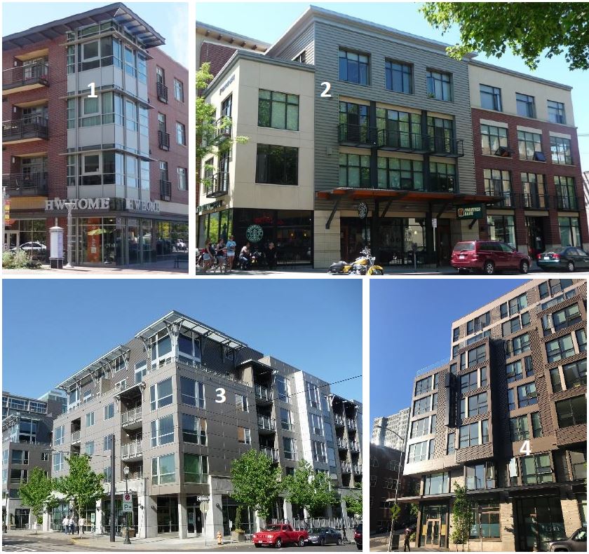
Buildings 1 and 2 successfully use metal siding more as an accent element to help articulate the facade. Metal siding is the primary material for Buildings 3 and 4, both of which integrate subtle changes in color to go with articulation features and design details.
3. Standards for the Use of Exterior Insulation and Finish System (EIFS). Such material/finishes may be used when it complies with the following:
a. EIFS is limited to no more than 20 percent of the total facade area and may not be the primary cladding material on nonresidential and mixed-use buildings.
b. EIFS must feature a smooth or sand finish only.
c. EIFS must be trimmed in wood, masonry, or other material and must be sheltered from weather by roof overhangs or other methods.
d. EIFS must not be used on the ground floor of facades containing nonresidential uses.
Departures will be considered provided the material’s integration and overall facade composition meets the purpose of the standards.
Figure 19.123.260(B)(3)
Acceptable and unacceptable EIFS examples.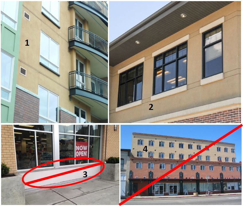
Buildings 1 and 2 mix EIFS with brick and other materials and integrate trim details around windows to add a sense of depth to the facade. Building 3 uses EIFS is between the window and sidewalk – this design is prohibited. Building 4 uses EIFS as the primary siding material, which is prohibited.
4. Cementitious wall board paneling/siding may be used provided it meets the following provisions:
a. Cement board paneling/siding may not be used on ground-level facades containing nonresidential uses.
b. Where cement board paneling/siding is the dominant siding material, the design must integrate a mix of colors and/or textures that are articulated consistent with windows, balconies, and modulated building surfaces and are balanced with facade details that add visual interest from the ground-level and adjacent buildings.
Departures will be considered provided the material’s integration and overall facade composition meet the purpose of the standards.
Figure 19.123.260(B)(4)
Acceptable and unacceptable cementitious wall board examples.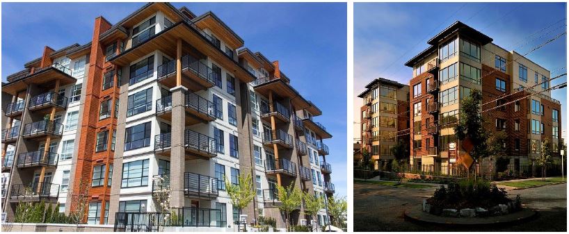
The above building uses cementitious wall board in different textures and colors to help articulate the facade. The white color replicates the board and batten style in the left image and green color in the right image effectively replicates horizontal wood siding.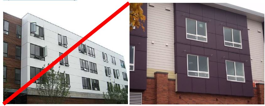
The wall board panels covering a large area in a single color would not meet the purpose of the standards. The right image is a better example and combines larger panels (dark maroon color) with horizontal wall board siding (beige color) as effective articulation features.
(Ord. 2755 § 3 (Exh. B), 2019).
19.123.270 Blank wall treatment.
A. Purpose.
1. To avoid untreated blank walls.
2. To retain and enhance the character of Mountlake Terrace’s streetscapes.
B. Blank Wall Definition. “Blank wall” means a ground floor wall or portion of a ground floor wall over 10 feet in height and a horizontal length greater than 15 feet and does not include a transparent window or door.
Figure 19.123.270(B)
Blank wall definition.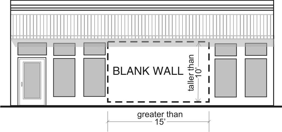
C. Blank Wall Treatment Standards. Untreated blank walls adjacent to a public street, pedestrian-oriented space, common usable open space, or pedestrian pathway are prohibited. Methods to treat blank walls can include:
1. Display windows at least 16 inches of depth to allow for changeable displays. Tack-on display cases (see Figure 19.123.270(C) below) do not qualify as a blank wall treatment.
2. Landscape planting bed at least five feet deep or a raised planter bed at least two feet high and three feet deep in front of the wall with planting materials that are sufficient to obscure or screen at least 60 percent of the wall’s surface within three years.
3. Installing a vertical trellis in front of the wall with climbing vines or plant materials.
4. Installing a mural as approved by the director and reviewed by the Arts Advisory Commission. Commercial advertisements are not permitted on such murals.
5. Special building detailing that adds visual interest at a pedestrian scale. Such detailing must use a variety of surfaces; monotonous designs will not meet the purpose of the standards.
For large visible blank walls, a variety of treatments may be required to meet the purpose of the standards.
Figure 19.123.270(C)
Blank wall treatment examples.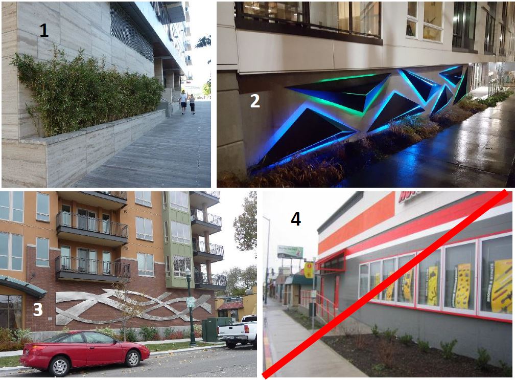
Buildings 1 – 3 feature acceptable treatments including a combination of high quality materials and landscaping (1), decorative lighting/sculptural element (2), and decorative artwork. The display cases in Building 4 don’t meet the 16" depth requirement, nor do they meet the purpose of the standards.
D. Firewalls. Firewalls along property lines are exempt from the above standards, but where they are visible to the public (from the adjacent street), they must be designed to provide visual interest from all observable distances. Examples may include the use of varying materials, textures, and/or colors, the use of green or living walls, and/or the use of modulated building walls to form design patterns.
Murals are also encouraged as a firewall treatment. Murals are subject to review by the Arts Advisory Commission and approval by the Director. Commercial advertisements are not permitted on such murals.
Figure 19.123.270(D)
Acceptable firewall design where visible to the public.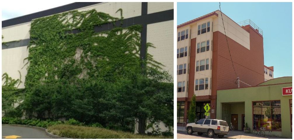
The left images uses a combination of paint bands and ivy to enhance the appearance of this large exposed firewall. The building in the right image uses simple scoring patterns and change in materials and color on part of the top floor to add visual interest.
|
|
Plain gray concrete block firewalls such as this are not allowed when visible from the street. |
(Ord. 2755 § 3 (Exh. B), 2019).