Appendices
Appendix 20C-1 Downtown Linkage System Construction Specifications
I. Need/Introduction
II. Landscaping
III. Timing of Required Installation
IV. Linkage System Requirements
I. Need/Introduction.
Purpose – In accordance with RCDG 20C.40.105-070 this appendix establishes the construction standards for linkage system walkway standards.
II. Landscaping.
A. Minimum landscaping standards are established by the Downtown Planting Requirements Chart, the Recommended Plant List and General Landscaping Specifications of the Development Guide.
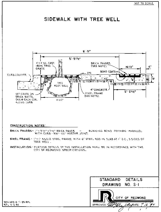
B. Street trees shall be planted within tree planters constructed in the sidewalk if the sidewalk abuts the back of curb. If trees cannot be planted within the treewells due to overhead and/or underground utilities, the trees may be planted behind the sidewalk.
C. Street trees may be planted between the curb and a meandering sidewalk if the minimum width of the landscape strip is three feet. This may be accomplished by providing a half-tree planter well within the sidewalk with a one-and-one-half-foot landscape strip.
D. All linkage system landscaped areas shall be irrigated.
III. Timing of Required Installation.
A. New Construction. All linkage systems shall be installed to City standards as specified in this section at the time new construction occurs.
B. Remodel. RCDG Title 20F governs the required improvements necessary in areas where the linkage system is nonconforming.
C. Split Improvements. In the case where an internal block linkage system is to be installed and the linkage system installation will involve more than one property owner, the applicant may use one of the following methods to determine which owner will install the different segments of the linkage system:
1. One property owner may install the sidewalk, landscaping, irrigation, street furniture, lighting and drainage and be compensated by the adjacent property owner for their fair share of the improvements.
2. The applicant may install 50 percent of the required improvements and the other property owner shall install the remaining improvements at the time of development.
IV. Linkage System Requirements.
A. Street Furniture.
1. Benches:
a. Number: The minimum lineal footage of seating is two feet per 60 feet of linkage system frontage or fraction thereof.
b. Location: Benches may be grouped to accent plazas, building entrances and other nodes of interest. Benches located along walkway shall be placed a minimum of two feet from the walkway, and pavement placed between the bench and walkway.
c. Installation: All benches shall be structurally sound and be secured to the point.
d. Style: Francis/Andrew Basic Bench Series 2, Big Toys Series 20 or approved bench of equivalent style.
e. General: Other seating may be substituted for benches subject to Design Review Board approval such as game tables, keblis benches, planters with seating ledge, and perching walls.
f. Exceptions:
i. Bench requirements may be waived by the Technical Committee if alternative methods of seating are provided such as planter wall or perching wall seating.
ii. Bench requirements may be waived for linkage systems which front on a street if the property is less than 200 feet in length along the said street. However, the Technical Committee or Design Review Board may require benches to be installed at key focal points or at the intersection of two linkage systems if it is felt the location of the benches will be a benefit to the City.
iii. The number of benches may be modified by the Technical Committee if the lot fronts on several linkage systems.
2. Waste Receptacle:
a. Number: The number of required waste receptacles shall be determined by a ratio of one receptacle per 200 feet of linkage system frontage or fraction thereof.
b. Location: Receptacles may be grouped to serve seating areas, plazas, or other nodes of interest. Receptacles shall be located on pads adjoining the walkway but not located directly upon the walkway.
c. Installation: All receptacles shall be structurally sound, securely fastened to the pavement, and have weep holes.
d. Style: Quality Industries Inc. litter receptacle No. 1617 or approved receptacle of equivalent style. All receptacles shall be round wood receptacles with top fastened to base and have a 26-gallon galvanized liner.
B. Walkway Lighting. The following walkway lighting shall be installed on all internal linkage systems and may be required on a site specific basis for all other linkage systems:
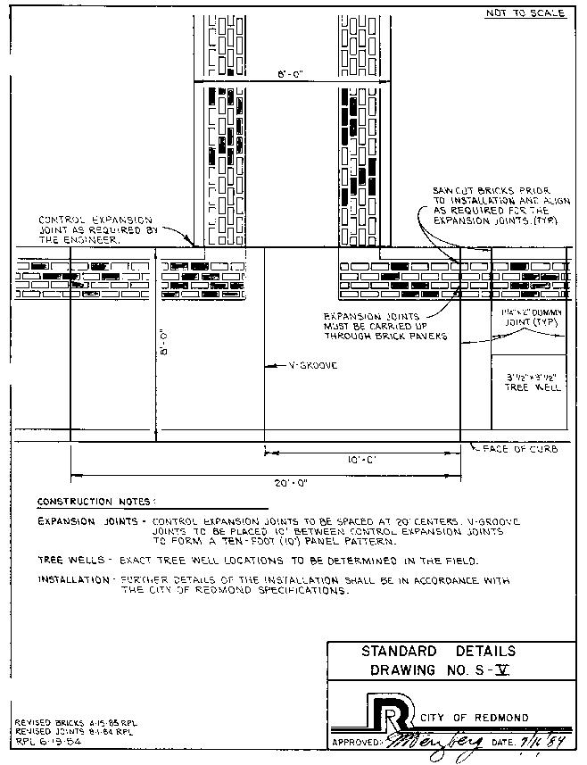
1. Illumination Level: Illumination shall be provided for the entire length of the walkway. The minimum illumination level is an average of one-half foot-candle and shall be provided by 100-watt sodium vapor light fixtures at a spacing and height specified by this section.
2. Spacing: Light fixtures shall be provided at a spacing from 40 feet to a maximum of 60 feet on center, and shall be staggered on opposite sides of the walkway. The starting point for spacing to be determined by City Engineer.
3. Height: The height of light fixtures shall be 14 feet.
4. Style: The style of light fixture shall be the Sterner Executive II or approved equivalent, with 100-watt sodium vapor luminaire. The style of the lighting pole shall be the Centrecon “S” Series octagonal-shape concrete pole with the No. 313 natural exposed buff finish, or approved equivalent.
5. General: Provision of special accent or feature lighting is encouraged.
C. Sidewalk Design.
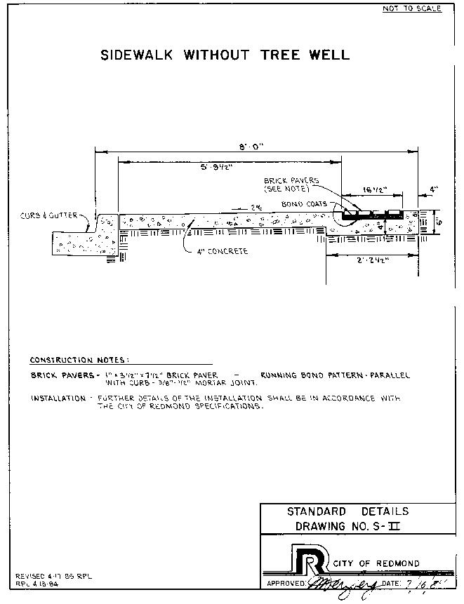
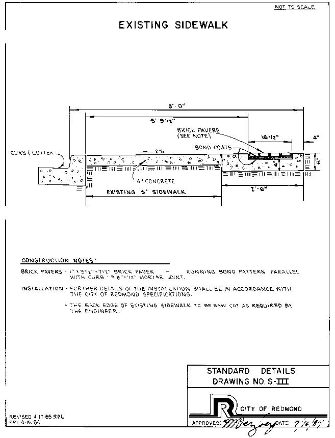
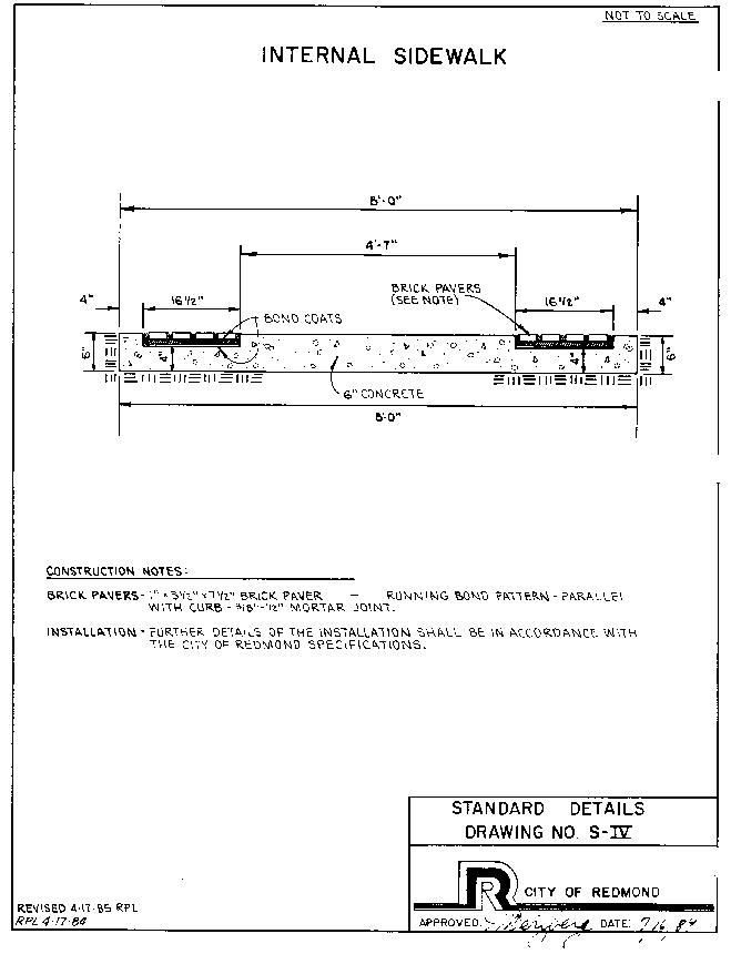
1. Width: All Downtown sidewalks shall be a minimum eight feet in width.
2. All Downtown sidewalks shall be constructed to City specifications as noted in this appendix and attached cross-sections.
3. The Technical Committee may alter the minimum eight-foot width if special circumstances arise.
4. Tree grates shall be:
a. Olympic Foundry 8045-56 or equivalent.
b. Size: 36 inches.
c. Sections Cast: two.
d. Hole Diameter: nine inches.
5. Other:
a. Provision of kiosks, water fountains, bicycle racks, tables and other forms of street furniture is encouraged and may be substituted for benches upon approval of the Design Review Board.
b. Brick paving in bench areas and to entries of buildings is strongly encouraged.
D. Cement Concrete Base Pavement.
1. Description: Cement concrete base pavement shall be constructed wherever brick paving is designated to be installed. This includes areas in the sidewalks, driveways, and crosswalks.
Cement concrete base pavement is intended as a base for brick pavers of varying depth. It shall meet the requirements of these specifications except that asphalt emulsion will not be allowed for use as a curing compound.
2. Materials: The class of concrete mix shall be 5-3/4 (1-1/4) six percent air entrained for all thickness of cement concrete base pavement shown in the standard plans.
3. Construction: The cement concrete base pavement shall conform to the sections shown on the standard plans. Cement concrete base pavement shall be six percent air entrained.
E. Cement Concrete Sidewalks.
1. Description: Cement concrete sidewalk shall be constructed in accordance with Section 42 of the APWA Standard Specifications, except as modified herein, as per detail drawing incorporated within these specifications and standard plan.
2. Materials:
a. Concrete Materials.
i. Portland Cement: ASTM C150, Type 1.
ii. Aggregate: ASTM C33, three-eighths-inch minus, standard Salmon Bay Pea Gravel. Provide aggregates from a single source for all exposed concrete. Local aggregate not complying with ASTM C33 but which have shown by special test or actual service to produce concrete of adequate strength and durability may be used when acceptable to the contracting agent.
iii. Water: Clean, fresh, drinkable.
iv. Air-Entraining Admixture: ASTM C260.
v. Water-Reducing Admixture: ASTM C494, Type A.
Calcium Chloride will not be permitted in concrete, unless authorized in writing by the City Engineer.
vi. Set Control Admixture: ASTM C494, Type B, Retarding.
b. Related Materials.
i. Washed Gravel: Either natural or crushed.
ii. Screeds: Two by four construction, tight knot cedar.
iii. Sealer: Sealer for exposed aggregate slab shall be Thompson Water Seal, or approved equal.
iv. Retardant: Sika Chemical Corp. “Rugasol-C”.
v. Anchor Bolts: ASTM A307.
vi. Pipe Sleeving: ASTM A36, ASA Schedule 40.
c. Concrete Mix.
i. Compressive Strength: 3,000 psi minimum at 28 days. Class 5-3/4(1-1/4) water content not to exceed 5.75 gals.
ii. Slump Range: Max. three and one-half.
iii. Air Content: Six percent plus or minus one percent.
iv. Admixtures: Use admixtures for water-reducing and set-control in strict compliance with the manufacturer’s directions.
v. Ready-Mix Concrete: Comply with requirements of ASTM C94, and as herein specified.
3. Execution.
a. Inspection: Examine the areas and conditions under which concrete curbs, walks and driveways are to be installed and notify contracting agent in writing of conditions detrimental to the proper and timely completion of the work. Do not proceed with the work until unsatisfactory conditions have been corrected in an acceptable manner.
b. Surface Preparation: Compaction of sub-base shall be to 95 percent as per APWA.
c. Adjustment of Utilities: Adjust existing and new building vents, fire hydrants, valves, etc., to meet required finish elevation and alignment.
d. Placing Reinforcement: Install welded wire fabric in as long lengths as practicable. Lap adjoining pieces at least one full mesh and lace splices with wire. Offset end laps in adjacent widths to prevent continuous laps in either direction. Place reinforcement to obtain at least the minimum coverage for concrete protection.
NOTE: Placing reinforcement may not be required on all projects and shall be reviewed on a case-by-case basis.
e. Wood Screeds: Two-inch by four-inch wood screeds shall be placed good edge up. Screeds shall have 12-inch long #4 reinforcing bars at four feet on center, horizontally through two inches by four inches. Screeds shall be staked with one-inch by two-inch by 18-inch fir stakes at three feet on center to secure. Care shall be taken to keep screeds plumb and in proper alignment and elevation during concrete placement.
NOTE: Wood screeds are not permitted within any public right-of-way. This specification shall only be used for inspection purposes within private development.
f. Embedded Items: Provide anchor bolts and pipe sleeves at locations and at elevations shown on drawings.
g. Concrete Placement: Deposit and consolidate concrete in a continuous operation, within the limits of construction joints, until the placing of a panel or section is completed.
Consolidate concrete during placing operations so that concrete is thoroughly worked around reinforcement and other embedded items and into corners.
Bring surfaces to the correct level with a straight-edge and strikeoff. Use bull floats or darbies to smooth the surface, leaving it free of humps or hollows. Do not sprinkle water on the plastic surface. Do not disturb the slab surfaces prior to beginning finishing operations. Maintain reinforcing in the proper position during concrete placement operations.
h. Finishing and Curing:
i. Exposed Aggregate: Expose aggregate before initial concrete sets by applying with roller Sika Chemical Corp. “Rugasol-C” per manufacturer’s specifications. Wash and brush with stiff-bristle brush for lite aggregate exposure. Submit two-foot by two-foot finish sample for approval before work is started.
Provide exposed aggregate finish as indicated on drawings. Exposed aggregate surface shall be hand exposed pebble aggregate finish with hard sharp true edges and corners with uniform coloration, integral aggregate mix of standard Salmon Bay Pea Gravel with a maximum diameter of three-eighths inch or as approved.
Protect freshly placed concrete from premature drying and excessive cold or hot temperature, and maintain without drying at a relatively constant temperature for a period of time necessary for hydration of cement and proper hardening.
Start initial curing as soon as free water has disappeared from concrete surface after placing and finishing. Weather permitting, keep continuously moist for not less than 72 hours.
Begin final curing procedures immediately following initial curing and before concrete has dried. Continue final curing for at least seven days and in accordance with ACI 301 procedures. Avoid rapid drying at end of final curing period.
NOTE: Exposed aggregate shall not be permitted within any public right-of-way. This specification shall only be used for inspection purposes within private developments. Also, no latents shall be deposited or washed into the storm sewer system.
ii. Finish: All public rights-of-way shall be finished according to this section.
After the concrete has been thoroughly compacted and leveled, it shall be floated with wood flats and finished at the proper time with a steel float. Joints shall be edged with a one-quarter-inch radius edger and the sidewalk edges shall be tooled with a one-half-inch radius edger.
Depending on the type, the sidewalk shall be divided into panels by scoring one-quarter inch deep in the manner shown on the standard drawing.
iii. Expansion Joints: As per 1982 Handbook for Ceramic Tile Installation, EJ71182, page 28.
4. Execution.
a. Existing Conditions: Verify that surface to receive brick paving is a smooth, even surface that shall provide finished grades indicated upon installation of brick. Surface to receive paving shall not vary more than one-quarter inch above and one-quarter inch below required plane. Notify General Contractor of any discrepancy in line or level. Expansion joints in concrete must be carried up through brick pavers.
Inspect Concrete for:
i. Cracks.
ii. Grease spots sealing agents and have removed prior to starting work. (Grease spots or remaining sealing agents will prevent proper bond.)
b. Installation:
i. Setting Bed for Brick: Well-Mixed Mortar – five parts mason’s sand, one part Portland cement, using five gallons of water per sack of cement to obtain a stiff mix. Mortar shall be stiff enough to compact by force, but loose enough for total imbedment of ribs on back of paver units.
(1) Lay out work to true lines, level and sloped to drain as required. Maintain the four-inch by eight-inch module of pattern indicated.
(2) Do no mortar work when temperature is below 40 degrees F., or in rainy weather unless under adequate cover. Deliver, store, and handle materials care fully to prevent damage by water, breakage, staining, or inclusion of dirt or foreign matter. Replace damaged or otherwise unsatisfactory material with new.
(3) Spread and compact setting bed to thickness required to provide for finish grades indicated.
(4) Do not lay pavers directly on setting bed, trowel or brush on a thin layer one-eighth-inch in thickness of neat cement over bed or trowel cement slurry directly onto the bed using a three-quarter-inch notched trowel.
(5) Set units while it is still plastic before initial set of bed and neat cement has taken place.
(6) Use story pole or rack method for layout and alignment.
(7) Beat paver units into total contact with plastic mortar. Set and level each area before the initial set. Do not set more than four rows at a time.
(8) All needed cuts of brick shall be accomplished with approved saw equipment; no brick is to be scored and broken. No paver shall be less than four inches long. Same day rough grout by sweeping a damp mixture of cement and sand (same mixture as deck mud) to within about one-half inch of the top of the pavers. Work off kneeling boards. Spray area off with a hose.
(9) Next Day Fine Grouting – Mix grout or pointing mortar, consisting of one part portland cement and one part dry mason’s sand, to a thick pouring consistency. Force into joints with trowel, cuts joint with trowel point to eliminate voids and to bond with rough grout. After joints have dried to thumbprint hardness, wipe off grout left on paver surface with dry burlap.
Clean pavers as work progresses to minimize final cleaning. Drag the surface of the pavers with damp heavy troweling or blankets; rinsing often in clean water. Continue to drag surface until all traces of mortar are removed and troweling or blankets rinse clean.
ii. Curling or Sealing: Cover area with polyethelyne covering. Restrict all traffic for 72 hours. Once cured, seal the area with commercial sealer. Sealer should contain not less than seven percent solids solvent based two floor coats.
(Owner or Architect/Engineer should obtain written warranty from contractor and sealer manufacturer as to precisely what work is being performed and what the results will be over what period of time.)
iii. Protection: Do not walk on pavers while work is in progress and do not allow foot or vehicular traffic for seven days. Provide adequate protection from damage, including staining and spillage, until final acceptance.
The surface shall be brushed with a fiber hair brush of an approved type in a transverse direction except that at driveway and alley crossings it shall be brushed longitudinally. The placing and finishing of all sidewalk shall be performed under the control of the Engineer, and the tools used shall meet with his approval.
Additional requirements for placing and finishing concrete in cold weather shall be as outlined in Section 39-3.21 as per APWA.
iv. Repairs and Protections:
(1) Repair or replace broken or defective concrete, as directed by contracting agent.
(2) Protect concrete from damage until acceptance of work. Exclude traffic from concrete for at least seven days after placement. When construction traffic is permitted, maintain concrete as clean as possible by removing surface stains and spillage of materials as they occur.
(3) Sweep concrete and wash free of stains, discolorations, dirt and other foreign material just prior to final inspection.
F. Brick Paving.
1. Description: Cement concrete base pavement of the class and thickness shown on the standard plans shall be constructed where brick paving is to be installed, and shall be as specified in Standard Details Drawing No. S-V.
2. Submittal Data: Submit certificate from manufacturer stating that brick pavers delivered to site conform to these specifications.
3. Products:
a. Brick Pavers:
i. Brick pavers to be red as manufactured by Mutual Materials Co. or Interpace. Size one inch by three and one-half inches by seven and one-half inches for all sidewalk runners and bands, three inches by three and one-half inches by seven and one-half inches for the driveway runners, crosswalks, and intersections.
ii. Pattern: Running Bond. All joints shall be three-eighths inch to one-half inch.
b. Bonding Agent: Grade Daraweld, Larson Products, Weldcrete, or Sonneborn Sonobond products.
(Ord. 2302. Formerly Appx. H)