


Chapter 28.44
STREETS
Sections:
28.44.020 Streets as part of the drainage system.
28.44.030 Drainage impacts on traffic and streets.
28.44.060 Temporary ponding and localized cross flow.
28.44.070 Pavement deterioration effects.
28.44.080 Sedimentation and debris.
28.44.090 Street classification and allowable flow depth and velocities.
28.44.100 Street hydraulic capacity evaluation.
28.44.110 Storm inlet selection, sizing, and location.
28.44.120 Hydraulic capacity of inlets on a continuous grade.
28.44.130 Hydraulic capacity of inlets in sump conditions.
28.44.140 Inlet clogging considerations.
28.44.150 Grate selection and rating.
28.44.160 Inlet location and spacing.
28.44.010 Introduction.
This chapter presents criteria regulating the design of public streets for storm flow drainage and allowable encroachment of these flows within public street rights-of-way. Also included herein are criteria for the selection and placement of storm drain inlets as required to conform to maximum allowable street ponding. All design submittals involving the utilization of public streets for the conveyance of storm flows shall be reviewed based upon the criteria in this chapter.
(Res. 40-08 (§ 1101), 3-19-08)
28.44.020 Streets as part of the drainage system.
The primary function of public streets is the movement of traffic. Therefore, use of streets as part of the drainage system must be limited in order to minimize interference with traffic functions. Street inundation and ponding limits are specified in this chapter in order to limit this potential interference. However, due to the nature of the storms typical to Mesa County, and the resulting ephemeral interference with traffic movement, these limits are not highly restrictive.
Streets typically convey runoff collected not only on the street surface itself, but often from some portion of the surrounding area as well. As an integral part of the drainage system, streets must be capable of conveying some portion of said runoff to a primary drainage conveyance facility such as a storm drain or open channel drainage system. The maximum allowable capacity of a street is based upon its cross-sectional configuration, longitudinal slope, and the maximum allowed ponding depth. Where the calculated minor storm event flow depth exceeds this maximum depth, inlets must be used to reduce street flow. During a major storm event, streets become emergency runoff channels, routing floodwaters away from structures as much as possible. During such an event, many streets will be inundated to a degree such that they are impassable to most vehicles.
(Res. 40-08 (§ 1102), 3-19-08)
28.44.030 Drainage impacts on traffic and streets.
A number of factors may affect traffic movement and the streets themselves when used for drainage purposes. Five of these factors are discussed in the following sections.
(Res. 40-08 (§ 1103), 3-19-08)
28.44.040 Sheet flow.
Rainfall on the paved surface of a street must flow overland (sheet flow) until it reaches a channel. In this case, the channel will be either a curb-and-gutter or a roadside ditch. Ignoring the effects of street inundation due to upgradient runoff, the depth of sheet flow will be near zero at the street crown, increasing in the direction of the collection channel (i.e., the gutter).
Sheet flow can interfere with traffic movement by increasing the risk of hydroplaning or splashing. Hydroplaning is a phenomenon in which one or more of a vehicle’s tires lose significant contact with the pavement and become supported by a thin layer of water. This water acts as a lubricant between the pavement and the vehicle, and can cause loss of vehicle control. The potential for hydroplaning increases with vehicle speed and with the depth of water on the road surface, so extra attention shall be paid to this issue during the design of arterial and highway-type roadways. Sheet flow depths can be decreased by increasing the street cross-slope.
Splashing is also dependent on vehicle speeds and water depth, and can interfere with traffic movement by reducing driver visibility. Again, increasing street cross-slope may help to reduce sheet flow depths and splashing potential. In general, a two percent cross slope is desirable to promote swift removal of runoff and reduce sheet flow depths while minimizing potential vehicle side-slippage from ice buildup during winter months.
(Res. 40-08 (§ 1103.1), 3-19-08)
28.44.050 Gutter flow.
Where curb-and-gutter is utilized, all runoff tributary to a street will be directed to, and flow in, a gutter until it reaches a storm drain inlet or other primary conveyance. Generally, flow width will increase in the downstream direction due to an ever-increasing tributary area (and thus higher flows), eventually spreading into the traffic lane(s) and to the street crown. It is important to take into account the gutter flow width and its effect upon traffic movement. For streets where on-street parking is allowed (e.g., residential streets), gutter flow may spread at least to the inner edge of the parking lane without interfering with moving traffic. However, where no street parking is allowed, flow spreading beyond the actual gutter almost immediately reaches a travel lane. Drivers tend to avoid even partially inundated lanes if possible, causing traffic congestion and occasionally vehicular collisions. However, some interference with traffic movement is allowable and expected, even during the minor storm. The duration of such interference is to be minimized wherever possible. Emergency vehicles must be able to travel all streets without encountering extensive (potentially vehicle-disabling) ponding depths. These depths are defined in GJMC 28.44.090 as maximum total gutter depths for the minor storm event.
(Res. 40-08 (§ 1103.2), 3-19-08)
28.44.060 Temporary ponding and localized cross flow.
Grade changes and street crowns at intersections can cause storm runoff to flow at depths greater than the intended design depth and to flow at greater depths for longer durations than anticipated. This localized, temporary ponding poses a high safety risk, especially on roads with higher speed limits (e.g., arterials). Because the ponding is localized, drivers may not be aware of the obstruction and vehicles may enter the ponded area at high speeds (see reference to hydroplaning, GJMC 28.44.040). Even if traffic is moving at low speeds, vehicles encountering a deeper ponded area may stop entirely to avoid entering such an area or may experience engine stalling while attempting to cross such an area. Both of these scenarios have the effect of reducing or halting traffic movement. Therefore, street and drainage design must incorporate measures to control the depths at locations where temporary ponding may occur through the use of grading changes or additional inlets. For streets with high traffic volumes, it may be necessary to take steps to effectively eliminate any temporary ponding in order to avoid extensive interference with traffic movement.
Cross flow occurs as a result of a number of scenarios that cause significant flow depths other than that which is the result of sheet flow to travel across traffic lanes. The most common location to encounter this phenomenon is at intersections where gutter flow from the cross-street spills across the intersection. Where allowable, a concrete V-pan may be utilized to control these flows (see City of Grand Junction Standard Details for Construction of Streets, Storm Drains and Utilities, Revised July 2005, page C-12). Localized cross flow can have the same negative effects on vehicular safety and traffic movement as general temporary ponding. Therefore, careful consideration shall be given to potential cross flow locations during design to minimize its effects, especially for streets with higher speed limits and/or higher traffic volume.
(Res. 40-08 (§ 1103.3), 3-19-08)
28.44.070 Pavement deterioration effects.
Utilization of streets for drainage of storm runoff can have a significant effect on roadway maintenance and repair and can, in certain cases, contribute to the structural failure of the roadway pavement. The latter situation may occur if water is able to penetrate the pavement and reach the subgrade. Subgrade saturation and/or material washout will eventually cause subgrade failure, leading to pavement failure and an unsafe/unstable road surface. These locations of distress are caused by other factors such as weathering, overweight vehicles, temperature and temperature changes, heavy traffic, machinery, pavement quality, subgrade inconsistencies, and pavement age. Water flow across undamaged pavement will not typically penetrate to the subgrade. Therefore, consistent roadway maintenance not only affects the efficiency of the street as a drainage system component, but can also reduce the likelihood of roadway failure due to the effects of ponding water.
Although undamaged pavement surfaces for the most part keep water from penetrating through to the subgrade, it is possible for some water to seep through with time. Street designs shall incorporate measures to decrease the duration for which a given section of pavement is submerged to minimize this seepage.
A common practice used to reduce the problem of bituminous surface deterioration is to seal-coat or overlay the existing pavement surface. While this method does effectively reduce pavement deterioration, it reduces the available street flow area with each layer added to the surface. To minimize this effect, it is recommended that the surface be scarified whenever possible before new layers of pavement are added.
(Res. 40-08 (§ 1103.4), 3-19-08)
28.44.080 Sedimentation and debris.
Sediment and debris buildup may occur on streets in any area where flow velocities tend to decrease such as near grade changes and inlets. Sediment and debris buildup can have a significant impact on the flow capacities of gutters and streets, causing increased flow width and thus increased interference with traffic movement.
Locations where significant deposits may occur shall be identified for maintenance purposes to include street sweeping and inlet cleanout as necessary. Inlets shall be designed to function properly based on expected sediment and debris clogging as specified later in this chapter.
Localized sedimentation issues due to construction activities shall be controlled per the criteria presented in Chapter 28.60 GJMC.
(Res. 40-08 (§ 1103.5), 3-19-08)
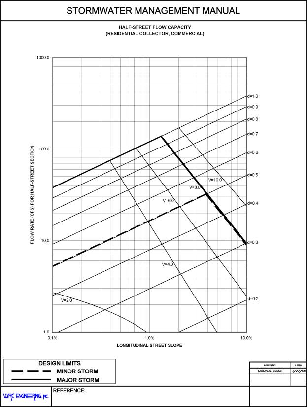
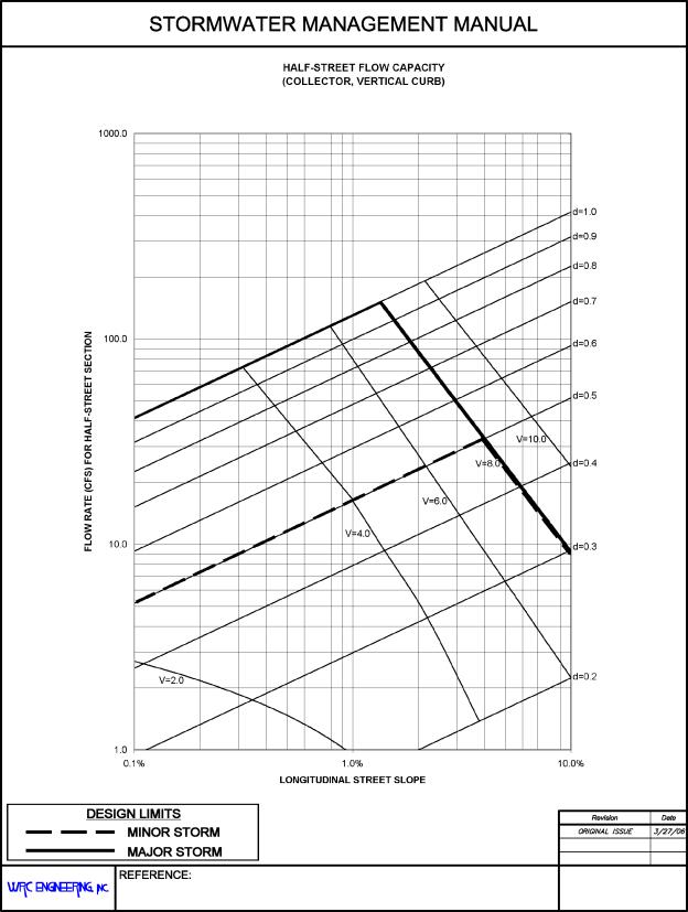
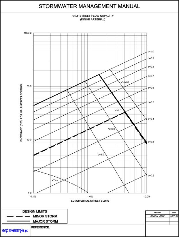
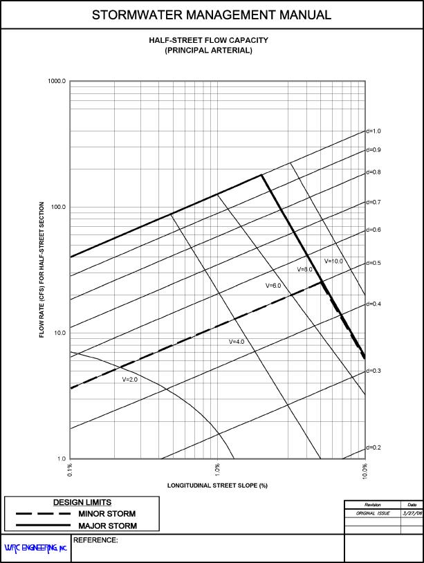
28.44.090 Street classification and allowable flow depth and velocities.
(a) Streets are classified according to estimated traffic volume and right-of-way width. The City of Grand Junction and Mesa County have adopted the Transportation, Engineering, and Design Standards (TEDS) manual (GJMC Title 29), including standard drawings and details for the construction of streets and location for utilities. While these drawings and details were developed and are maintained by the Grand Junction Department of Public Works and Utilities (Engineering Division), they have been adopted by the Mesa County Board of Commissioners (TEDS Chapter 1, p.1). Eight street classifications are specified therein, but some of these have been grouped together in this manual due to similar hydraulic characteristics. The rural roadway street type is not presented in this chapter since it utilizes a roadside ditch and culverts instead of curb-and-gutter. See Chapter 28.32 GJMC for open channel design criteria.
(b) The local jurisdictions within Mesa County have adopted the policy that streets can be used to convey storm runoff subject to the limits established by this manual. For the minor storm event:
(1) Flow depths must not exceed 0.5 feet at the gutter flowline;
(2) Must not exceed curb height (varies); and
(3) Flow velocities must not exceed 8.0 feet per second.
(c) Street flow depth from the major storm event must not exceed 1.0 foot from the gutter flowline and the flow velocity must not exceed 8.0 feet per second.
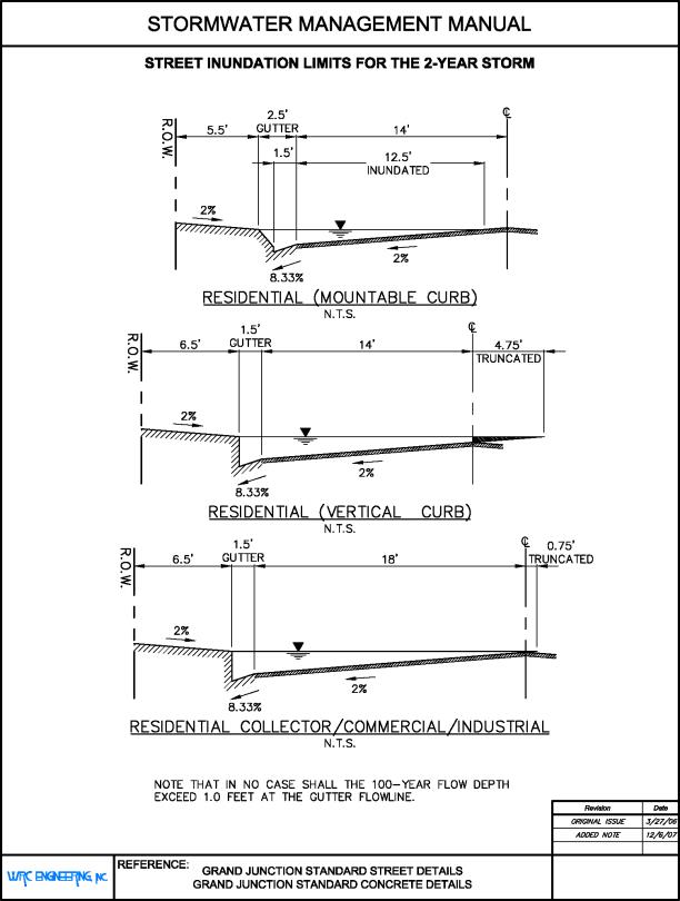
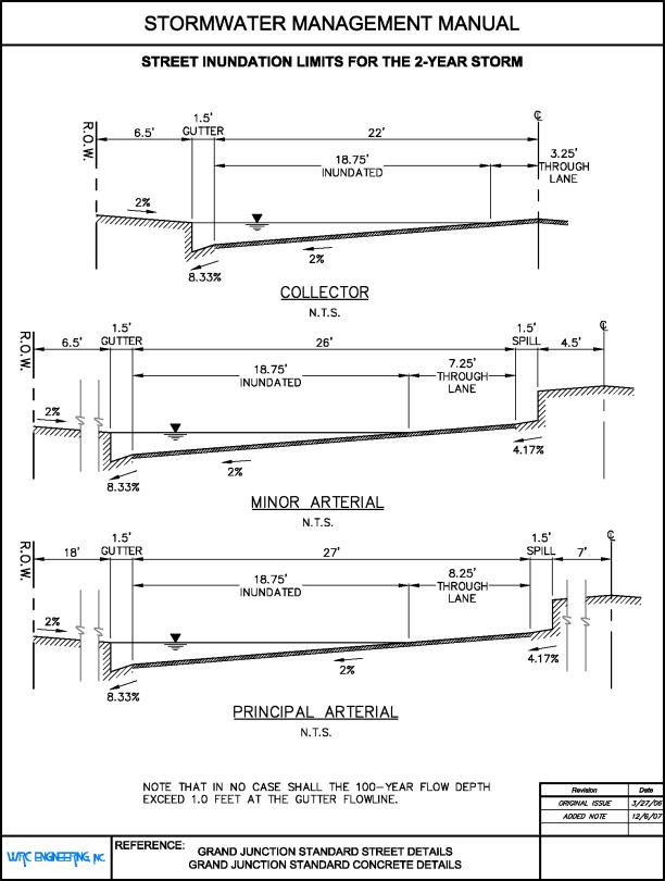
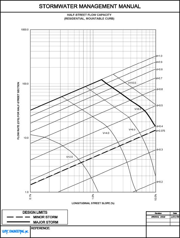
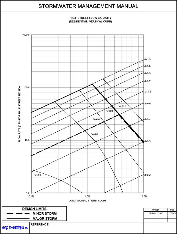
(d) Figures 28.44.090(a) and 28.44.090(b) show typical half-street sections and two-year storm event inundation limits for each street classification group. Note that the cross-sections shown include geometric assumptions made for hydraulic computation purposes and do not precisely reflect the approved standard street details.
(e) Calculations for flow capacity and velocity in a given street section are based upon these maximum depths and the assumption that any area not within the street right-of-way would not contribute to the capacity of the street system (called “ineffective flow area”). Therefore, for calculation purposes, it is assumed that an infinitely high vertical wall of zero roughness exists at the right-of-way boundary, and any flow area outside this boundary is not considered in analysis. Due to the potential for a single street cross-section to have different half-street cross-sections, all street capacity calculations are to be completed on a half-street basis. Therefore, the same vertical-wall assumption applies to the street centerline as to the right-of-way where the calculated flow width exceeds the half-street width.
(f) At street sag locations, pipes and/or channels must be provided to facilitate compliance with maximum ponding depths for both minor and major storm events as described above. Maintenance access must be provided for these facilities, including permanent easements.
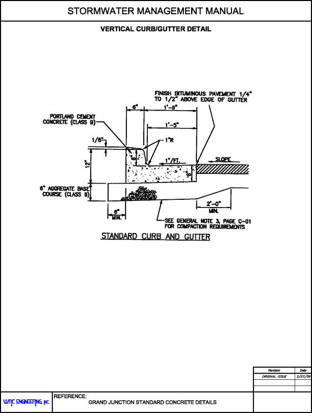
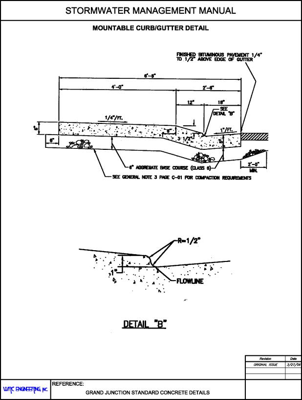
(g) Not inclusive of median spill gutters, the standard concrete details include two curb types, vertical and drive-over (mountable). The vertical curb configuration may be constructed monolithically with or without a sidewalk, and has a height of six inches. This configuration or an approved alternative design must be used for streets with an A.D.T. value of more than 1,000 (Standard Street Details, Page ST-05). A cross-section detail of the vertical curb and gutter is found in Figure 28.44.090(c). The drive-over, or mountable, curb configuration may only be used for residential streets with an A.D.T. value of less than 1,000 (Standard Street Details, Page ST-05). The total vertical height from the gutter flowline to the top of the curb is 4.5 inches, resulting in a lower maximum minor storm event water surface elevation for streets utilizing this gutter type. It does, however, reduce the need for driveway ramps, which are often a major contributor to the reduction of residential gutter capacity. Figure 28.44.090(d) is a detail of the standard mountable curb.
(Res. 40-08 (§ 1104), 3-19-08)
28.44.100 Street hydraulic capacity evaluation.
(a) Gutter and street flow can generally be assumed to be uniform for the purpose of hydraulic evaluation and design, but as street flow depth increases, flow width increases at a much faster rate. This wide, relatively shallow flow has the effect of decreasing the hydraulic radius, rendering the standard Manning’s equation somewhat inaccurate. The Federal Highway Administration (FHWA) presents a modified form of the equation in Section 5.3.2 of Introduction to Highway Hydraulics, taken from HEC-12:
|
|
(28.44-1) |
Where:
|
QS |
= |
Street Flow Capacity (not including gutter) (cfs) |
|
n |
= |
Manning’s Roughness Coefficient |
|
Ku |
= |
0.56 for English units |
|
Ku |
= |
0.376 for S.I. units |
|
SX |
= |
Street Cross Slope (ft./ft.) |
|
SL |
= |
Street Longitudinal Slope (ft./ft.) |
|
TS |
= |
Flow Top Width (not including gutter) (ft.) |
(b) For streets with a single cross slope for the gutter and street section, Equation 28.44-1 will suffice for determining total gutter/street flow capacity if the TS term is replaced by T = Total Flow Top Width (including gutter, inside curb). However, the standard concrete details indicate the use of composite cross slopes for all streets – the gutter has a steeper cross slope than the street. In these cases, the above equation specifies capacity in the flow area between the edge of pavement (not including the gutter itself) and the edge of flow. Note that the result of the same equation as applied to any flow area beyond the street centerline must be subtracted from the total capacity (see Figure 28.44.090(a)). The total flow capacity in the street and the gutter is calculated as:
|
|
(28.44-2) |
|
|
(28.44-3) |
Where:
|
SW |
= |
Gutter Cross Slope (ft./ft.) |
|
SX |
= |
Street Cross Slope (ft./ft.) |
|
T |
= |
Top Width (inside curb) (ft.) |
|
W |
= |
Gutter Width (ft.) |
(c) Figures 28.44.100(a) through 28.44.100(f) show calculated half-street flow capacities for each street classification group based on longitudinal street slope and flow depth. The HEC-12 equation (Equation 28.44-1) was used to determine most flow capacities for these charts except in cases where the flow width does not exceed gutter width. Where gutter flow does not encroach on the street surface, it is assumed that the width to depth ratio is not large enough to warrant the utilization of the HEC-12 modified Manning’s equation. Instead, the standard form is used in these cases:
|
|
(28.44-4) |
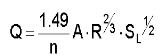
Where:
|
Q |
= |
Flow Capacity (cfs) |
|
SL |
= |
Street Longitudinal Slope (ft./ft.) |
|
R |
= |
Hydraulic Radius (ft.) = A/P |
|
A |
= |
Cross-Sectional Flow Area (sf) |
|
P |
= |
Wetted Perimeter (ft.) |
(d) Major storm event flow depth may exceed curb height, thus the flow area behind the curb – between the curb and the right-of-way – must also be considered in the calculation of total street capacity. The flow in this area is found using Equation 28.44-1, replacing TS with TB = Flow Top Width (behind curb). Note that the truncation procedure described above must also be applied here if the calculated top width extends beyond the right-of-way boundary. Therefore, the total flow between the curb and street centerline, QB, is:
|
|
(28.44-5) |
(e) Total street capacity, then, is the sum of the resulting values from Equations 28.44-2 and 28.44-5. The HEC-12 procedure has certain limitations and includes certain assumptions. The most applicable of these are listed below.
(1) One value for Manning’s roughness n must be used for the entire cross-section. This can be a composite value derived from multiple roughness segments in the cross-section.
(2) The HEC-12 method ignores any roughness characteristics of the vertical segment of the curb. The energy-dissipating effect of this portion is considered to be negligible when compared to the wide bottom sections.
(3) The vertical curb shown in Figure 28.44.100(g) actually slopes back away from the street by one inch while rising six inches. This slope is ignored by the HEC-12 equations. The gutter width is assumed to include this extra one inch with a vertical segment of six-inch height at this point. See Figure 28.44.100(g) for detail.
(4) The standard concrete details indicate that the edge of the roadway pavement shall be one-quarter inch to one-half inch above the edge of the concrete gutter. The HEC-12 method is unable to account for this directly, and the hydraulic effects are assumed to be negligible, so this is ignored.
(f) Two of the provided standard street capacity charts, Figures 28.44.100(a) and 28.44.100(f), were not prepared using the procedure described above. Both residential streets with mountable curbs (Figure 28.44.100(a)) and principal arterials (Figure 28.44.100(f)) have a more complex cross-section than the HEC-12 method can accurately model. The former is due to the alternate curb-and-gutter configuration, and the latter has a required median to which the flow can spread, adding another flow-control surface to the cross-section. Therefore, Haestad Methods’ FlowMaster computer program was used to model these sections and prepare capacity charts. The program uses the Cox open-channel weighting method to determine composite roughness and utilizes the standard form of Manning’s equation to compute discharge.

(g) Certain assumptions were made in the creation of the street capacity charts to minimize the required number of figures and to simplify the design process. However, it is the responsibility of the designer to ensure that each assumption is valid for a specific design.
(1) A Manning’s roughness value of n = 0.016 was assumed for all flow surfaces encountered within the street right-of-way when using the HEC-12 method. Varying values of n were used to construct the FlowMaster cross-sections, but composite roughness values were not significantly different from 0.016 for the two special cases.
(2) A street cross slope of 2.0 percent was assumed for all streets.
(3) A gutter cross slope of 8.33 percent was assumed for all gutters.
(4) Velocity curves are provided on the capacity charts for reference only – the designer is responsible for the calculation of actual gutter velocities.
(h) In cases where these assumptions may not be valid, such as designs incorporating the use of nonstandard street sections, the designer shall utilize the equations presented above to determine allowable street capacity.
(i) The maximum allowable gutter velocity is 8.0 feet per second. Velocities exceeding this value can create safety issues, cause erosive damage to the street and other surfaces, and reduce the effectiveness of storm drain inlets.
(Res. 40-08 (§ 1105), 3-19-08)
28.44.110 Storm inlet selection, sizing, and location.
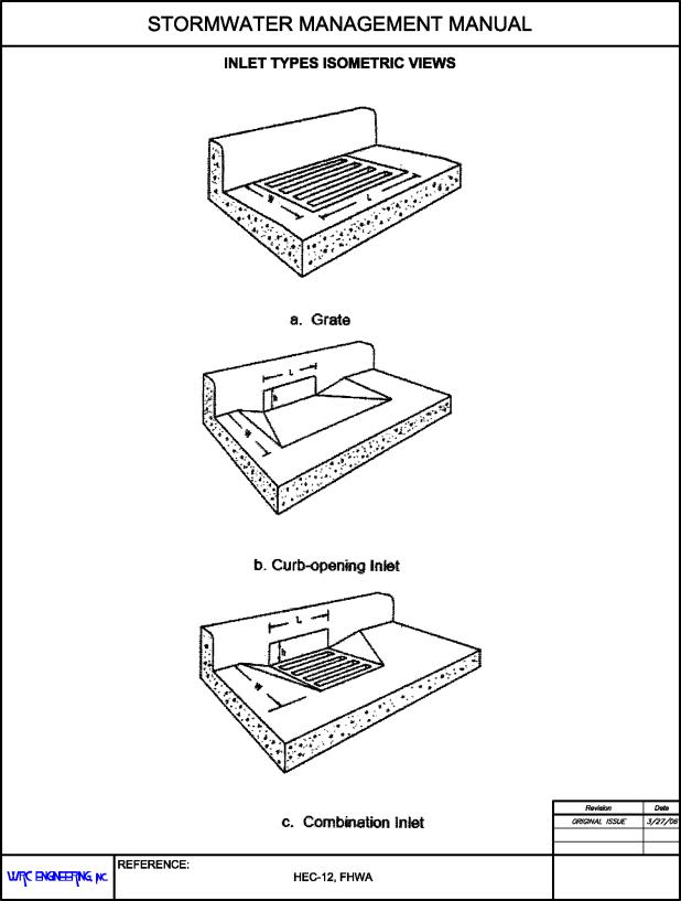
(a) Wherever street and gutter capacity exceeds allowable values based on flow spread, velocity, or depth, some or all of the runoff must be intercepted and diverted to an alternate flow path such as a storm drain or designated runoff channel. The most common method of interception is by the utilization of storm drainage inlets, of which there are four major types:
(1) Curb-opening inlets;
(2) Grate inlets;
(3) Combination inlets (curb-opening and grate);
(4) Slotted drain inlet.
(b) The slotted drain inlet is not recommended due to its high susceptibility to clogging, and may only be used where specifically approved by a local jurisdiction. All inlets must be labeled with “NO DUMPING – DRAINS TO RIVER.” Isometric-view examples of the first three types are shown in Figure 28.44.110.
(c) Inlets may either be located on a continuous grade – where flow not intercepted by the inlet will pass to another location – or in a sag portion of a street’s vertical alignment (or any other sump location). Computation of inlet capacity involves several factors including type of inlet, location (on-grade or in a sump), grate type (if applicable), inlet geometry, flow width and depth, and both longitudinal and cross slopes.
(d) Methods and rationale utilized in this chapter for the calculation of inlet capacities are based on those presented in HEC-12 (1984). However, HEC-12 contains a nomograph for finding grate splash-over velocity, and here we use an empirical formula for this value (Guo, Storm Water System Design, CE 5803, University of Colorado at Denver, 1999). Additionally, clogging must be considered in the selection and location of inlets, and will be addressed in GJMC 28.44.140.
(Res. 40-08 (§ 1106), 3-19-08)
28.44.120 Hydraulic capacity of inlets on a continuous grade.
Gutter velocities exceeding a “splash-over” velocity and flow widths greater than grate widths typically result in interception efficiencies of less than 100 percent for an on-grade inlet. Inlet efficiency, E, is defined as:
|
|
(28.44-6) |
Where:
|
Qi |
= |
Intercepted Flow Rate |
|
Q |
= |
Gutter Total Flow Rate |
Flow which is not intercepted by the inlet is called bypass flow, Qb:
|
|
(28.44-7) |
The interception efficiency of an inlet is affected by different factors for different inlet types. Grate inlets are most sensitive to the amount of water flowing directly over the grate (frontal flow) and the velocity of flow in the gutter. Curb-opening inlets vary primarily with inlet length, depth of flow, and both longitudinal and cross slopes of the gutter and street. Combination inlets where the curb opening and grate inlets are of similar length and are installed adjacently have been shown to have essentially the same interception capacity as the same grate configuration acting without a curb opening. However, curb-opening inlets have greater debris-handling capabilities than grates, and therefore combination inlets typically experience significantly less grate clogging than would be experienced if the curb-opening was excluded. A “sweeper inlet” is a type of combination inlet that utilizes a segment of curb opening upstream from the grated portion. This configuration has the highest debris-removal efficiency, and therefore lowest clogging rate, of all types listed here. Total capacity is the sum of the flow intercepted by the curb opening located upstream of the grate(s) and that intercepted by the grated portion of the combination inlet.
(a) Grate Inlets. Grand Junction Standard Storm Drain Details (Page D-05, 2005) lists storm drain grate types which have been approved for use. The four primary types for use on streets are Types R, L, V, and D in single, double, and triple-inlet configurations, and are included in the inlet capacity charts provided herein. Page D-05 also contains two important notes concerning the selection of grates:
(1) Use Type R or Type D grate where inlet is located in sump condition.
(2) Use Type V or Type L where gutter flow is from one direction only.
Type V and Type L grates are vane grates, which are more efficient for on-grade locations, but are very inefficient for sump conditions. Therefore, local jurisdictions do not allow the use of grate Types V and L for locations where sump conditions may exist. However, these types are recommended for on-grade locations where bicycle traffic is expected.
The FHWA and others have extensively researched the hydraulic characteristics of the seven grate types listed in Table 28.44.120. The approved grate types were each matched to the FHWA grate type most closely matching in geometry and apparent hydraulic functionality. These assumed pairings are indicated in Table 28.44.120.
The total rate of intercepted flow by a grate inlet (or standard combination inlet) is the sum of the intercepted frontal flow and the intercepted side flow. Frontal flow, Qw is that portion of the total gutter flow which has a flow width equal to or less than the grate width. Total frontal flow is found using the following HEC-12 equation:
|
|
(28.44-8) |
Where:
|
QW |
= |
Total Frontal Flow (cfs) |
|
Q |
= |
Total Gutter Flow (no behind-curb flow) (cfs) |
|
W |
= |
Width of Grate (ft.) |
|
T |
= |
Total Top Width of Flow (ft.) |
Total side flow is that portion of total gutter flow which is between the inner edge of the grate(s) and the street centerline, and is the remainder of the total flow between the curb and the centerline:
|
|
(28.44-9) |
Where:
|
Qs |
= |
Total Side Flow |
To find the ratio of intercepted frontal flow (Qwi) to total frontal flow (Qw), Rf, one must first find the splash-over velocity, Vo, for the selected grate type. This function was developed empirically by Guo (1999):
|
|
(28.44-10) |
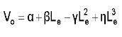
Where:
|
Le |
= |
Effective Unit Grate Length (see Equation 28.44-24) |
|
α, β, γ, η |
= |
Splash Velocity Constants (see Table 28.44.120) |
|
Type of Grate |
Assumed Equivalent |
α |
β |
γ |
η |
|---|---|---|---|---|---|
|
Bar P-1-7/8 |
Type D |
2.22 |
4.03 |
0.65 |
0.06 |
|
Bar P-1-1/8 |
Not used |
1.76 |
3.12 |
0.45 |
0.03 |
|
Vane Grate |
Type L,V |
0.30 |
4.85 |
1.31 |
0.15 |
|
45-Degree Bar |
Not used |
0.99 |
2.64 |
0.36 |
0.03 |
|
Bar P-1-7/8-4 |
Not used |
0.74 |
2.44 |
0.27 |
0.02 |
|
30-Degree Bar |
Not used |
0.51 |
2.34 |
0.20 |
0.01 |
|
Reticuline |
Type R |
0.28 |
2.28 |
0.18 |
0.01 |
|
Adapted from Guo, Storm Water System Design, 1999. |
|||||
Splash-over velocity is an experimentally-derived value at which frontal flow begins to bypass the grate essentially because water does not spend enough time over the inlet to allow it to fall through the grate. As previously mentioned, this value varies per grate type – some grates tend to better capture higher velocity flows. This allows the designer to calculate the HEC-12 frontal flow interception ratio:
|
|
(28.44-11) |
Due to the primarily longitudinally-flowing nature of street and gutter flow, the interception ratio of side flow is typically minimal, and in some jurisdictions is ignored altogether. This ratio, Rs, is defined as:
|
|
(28.44-12) |
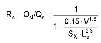
Where:
|
Qsi |
= |
Intercepted Side Flow (cfs) |
|
V |
= |
Gutter Flow Velocity (fps) |
|
Sx |
= |
Street Cross Slope |
|
Le |
= |
Effective Length of Grate(s) (ft.) (see Equation 28.44-24, GJMC 28.44.140) |
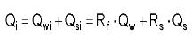
Total intercepted flow (Qi), then, is found using Equation 28.44-13:
|
|
(28.44-13) |
Total capture efficiency (E) for a grate inlet can be found using:
|
|
(28.44-14) |
Inlet clogging due to the buildup of debris and sediment can adversely affect the interception capacity of an inlet. A clogging factor must be applied to find the design value for Qi. See GJMC 28.44.140 for an explanation of the calculation of clogging factors.
Included in Figures 28.44.120(b) through 28.44.120(k) are inlet capacity charts for all street types and curb-and-gutter and inlet configurations considered by this manual. Figure 28.44.120(a) is a legend for these figures. The capacity curves are specific to grate type, inlet type, and whether the subject inlet is single, double, or triple length. All curves include appropriate clogging factors per GJMC 28.44.140. Inlet capacity values calculated from the provided equations may be used if they do not exceed the values provided in the inlet capacity charts.
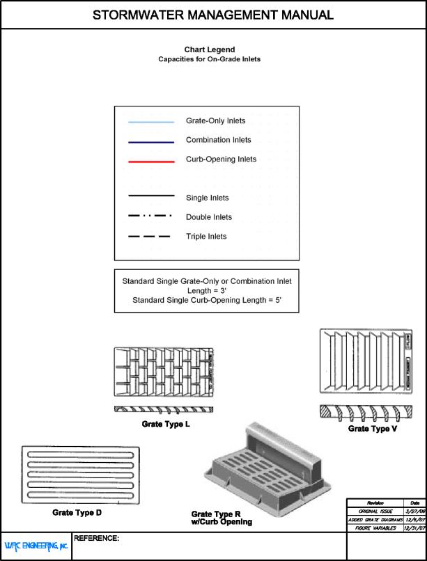
FIGURE 28.44.120(a)
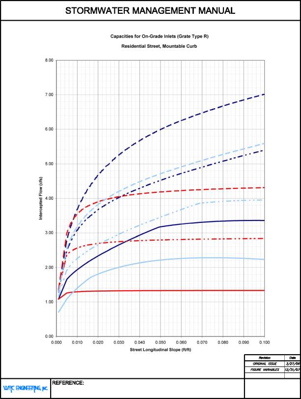
FIGURE 28.44.120(b)
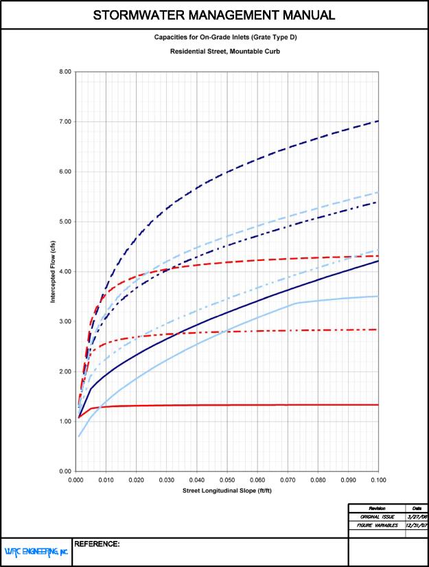
FIGURE 28.44.120(c)
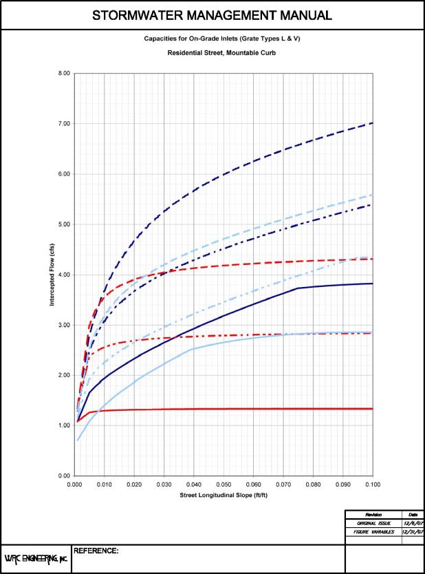
FIGURE 28.44.120(d)
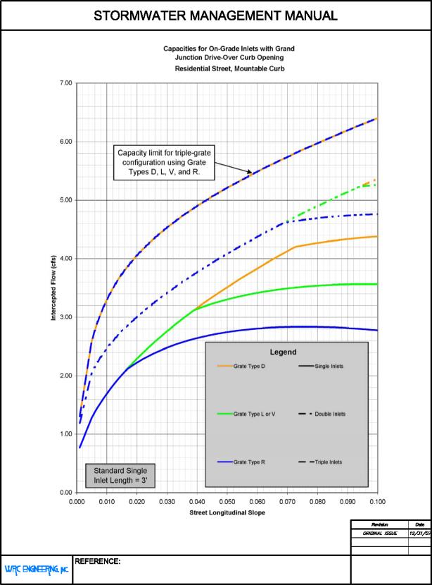
FIGURE 28.44.120(e)
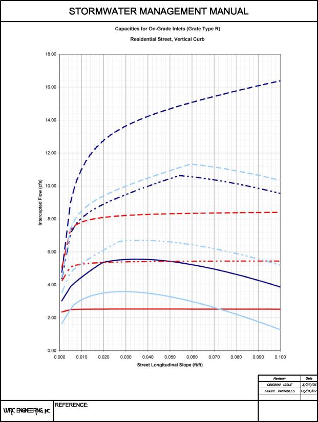
FIGURE 28.44.120(f)
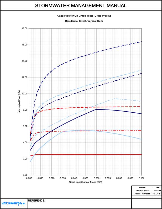
FIGURE 28.44.120(g)
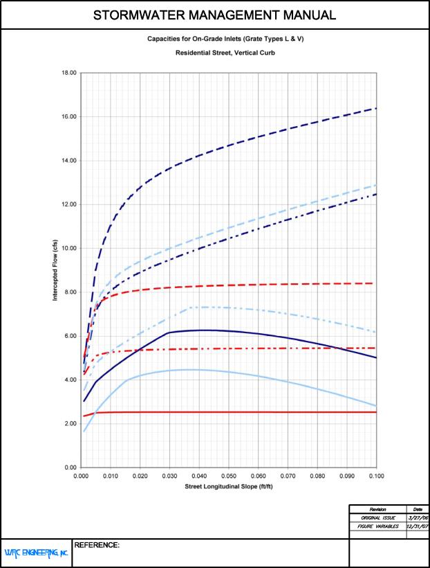
FIGURE 28.44.120(h)

FIGURE 28.44.120(i)
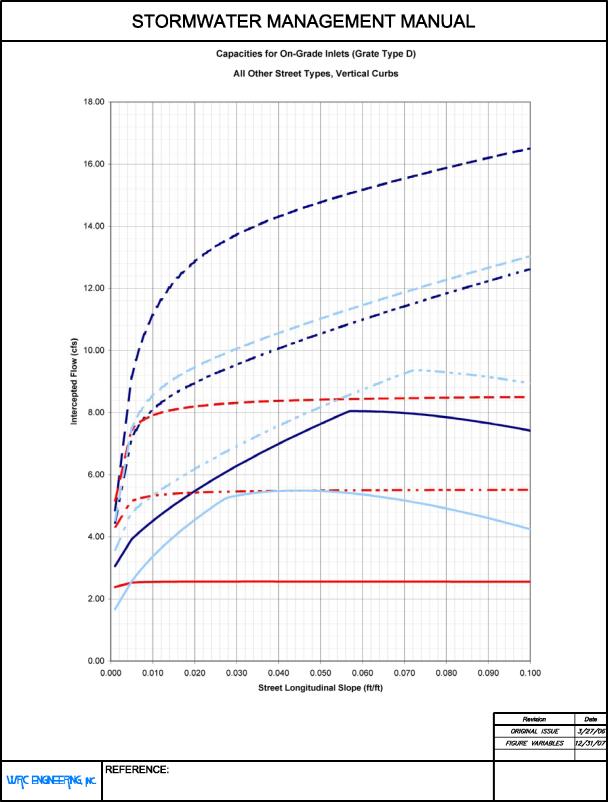
FIGURE 28.44.120(j)
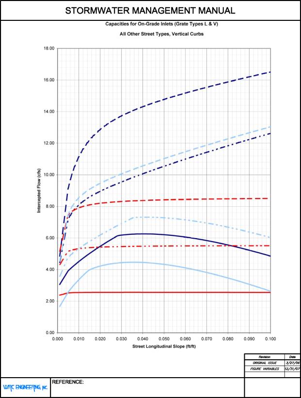
FIGURE 28.44.120(k)
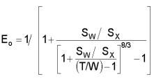
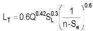
(b) Curb-Opening Inlets. The interception capacity of a curb-opening inlet on a continuous grade is dependent on inlet length, flow depth, and the longitudinal and cross slopes of the street. To determine the capture efficiency of a curb-opening inlet, one must first calculate the length that would be required for 100 percent interception of the gutter flow at that location (LT):
|
|
(28.44-15) |
|
|
(28.44-16) |
Where:
|
Q |
= |
Total Gutter Flow (cfs) |
|
SL |
= |
Longitudinal Street Slope |
|
n |
= |
Manning’s Roughness Coefficient |
|
Se |
= |
Equivalent Cross Slope |
|
SX |
= |
Street Cross Slope |
|
a |
= |
Gutter Depression Below Street Slope (ft.) |
|
W |
= |
Gutter Width (ft.) |
|
Eo |
= |
Defined by Equation 28.44-3 |
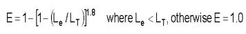
The efficiency of a curb-opening inlet is calculated using Equation 28.44-17, where effective length Le is defined in Equation 28.44-24 (GJMC 28.44.140):
|
|
(28.44-17) |
Included in Figures 28.44.120(b) through 28.44.120(k) are inlet capacity charts for all street types, grate types, inlet types and curb-and-gutter configurations considered by this manual. Each figure is specific to the type of grate used. The capacity curves for all on-grade inlets are specific to a single inlet length of 5.0 feet for curb-opening-only inlets and 3.0 feet for both grate-only and combo inlets. Figure 28.44.120(e) is the inlet capacity chart for the Grand Junction Drive-Over inlet with its own legend. It assumes the curb height is 4.5 inches, the flow line of the frame and grate is one inch below normal gutter flow line, and the vertical opening is set at one inch in height. Curves are provided for single, double, or triple length. All curves include appropriate clogging factors per GJMC 28.44.140. Inlet capacity values calculated from the provided equations may be used if they do not exceed the values provided in the inlet capacity charts.
(c) Combination Inlets. Per the introduction to this section, combination inlets are assumed to have the capacity of the same inlet with the grate(s) acting alone except in the case of “sweeper inlets.” However, the designer shall note the reduced clogging susceptibility of the combination inlet when compared with a grate-only configuration noted in GJMC 28.44.140.
(d) Slotted Drain Inlets. Slotted drains are effective for intercepting flow over a wide section, such as sheet flow across the pavement of a street. However, these inlets are highly susceptible to clogging, and are only allowed as specifically approved by a local jurisdiction. Methods for the design of such inlets can be found in HEC-12 and HEC-22.
(Res. 40-08 (§ 1106.1), 3-19-08)
28.44.130 Hydraulic capacity of inlets in sump conditions.
A sag or sump condition occurs in a location where water that flows into the area must pond to some depth before any of the flow can escape the area via channel or overland flow. Unlike inlets on a continuous grade, those in a sump condition are not designed to bypass a portion of the flow incident to the inlet location. This means that these inlets must have the capacity to effectively capture all of the runoff that ponds in the sump and to maintain acceptable ponding depths.
These requirements, along with an increased potential for inlet clogging due to low flow velocities, necessitate special provisions for the design of sump inlets. A secondary flow path must be provided to maintain a reasonable ponding depth in the case of inlet failure (near-complete clogging, for instance). The preferred secondary flow path is a designated emergency overflow weir and channel, which must be located within an accessible drainage easement and must be protected from erosive effects as necessary by pavement or riprap. If no easement is available at the inlet location, flanker inlets must be installed in the same gutter on each side of the primary inlet. Flanker inlets are located upgradient 10 to 50 feet from the primary sump inlet. The two flanker inlets shall have a combined design capacity equal to or greater than that of the primary inlet.
Local jurisdictions recommend the use of combination inlets in sumps due to their higher capacity and lower clogging tendency. Curb-opening inlets are also allowable, but grate-only inlets and slotted-drain inlets are not allowed for use in sump conditions.
Per GJMC 28.44.120(a), Type L and Type V grates are prohibited for use with inlets located in sumps. Mesa County and the City of Grand Junction have approved grate Types D and R for inlets in these locations.
The hydraulic capacity of an inlet in a sump condition is dependent on the configuration of the inlet and the depth of the ponded water. At small depths, the flow into the inlet is by weir flow, transitioning to orifice flow at increasing depths. These depths are defined in Table 28.44.130.
The gross capacity of an inlet operating as a weir is defined by Equation 28.44-18:
|
|
(28.44-18) |
Where:
|
Qi |
= |
Inlet Capacity (cfs) |
|
LW |
= |
Weir Length (ft.) |
|
d |
= |
Flow of Ponding Depth (ft.) |
|
CW |
= |
Weir Discharge Coefficient (see Table 28.44.130) |
The gross capacity of an inlet operating as an orifice is defined by Equation 28.44-19:
|
|
(28.44-19) |
Where:
|
Qi |
= |
Inlet Capacity (cfs) |
|
Ao |
= |
Orifice Open Area (sf) |
|
g |
= |
32.2 ft./s2 |
|
do |
= |
Depth to Orifice Centroid (ft.) |
|
Co |
= |
Orifice Discharge Coefficient (see Table 28.44.130) |
|
Type of Inlet |
Cw |
Co |
Weir |
Orifice |
Lw |
|---|---|---|---|---|---|
|
Grate |
3.00 |
0.67 |
d < 1.79(Ao/Lw) |
d > 1.79(Ao/Lw) |
2w+L |
|
Curb-Opening |
3.00 |
0.67 |
d < h |
d > 1.4h |
L |
|
Depressed Curb-Opening |
2.30 |
0.67 |
d < h + a |
d > 1.4h |
2w+L |
Where:
|
Ao |
= |
Orifice Open Area (sf) |
|
LW |
= |
Weir Length (ft.) |
|
d |
= |
Flow or Ponding Depth |
|
w |
= |
Grate Width (ft.) |
|
L |
= |
Inlet Length (ft.) |
It is important to note that the capacity of a combination inlet in a sump is defined by the capacity of the grate portion only when operating as a weir (the curb opening is ineffectual and thus ignored), but is defined by the cumulative capacity of the grate and curb opening when operating as an orifice. Any curb opening length extending beyond the ends of the grates may be included in the weir length.
For any given inlet, a certain range of depths will result in transitional flow, where neither the weir equation nor the orifice equation accurately models flow through the inlet. Linsley (1992) states that where transition conditions exist, “the capacity is intermediate between that of an orifice and a weir.” For design purposes, the capacity for depths in the transitional range is based on the lesser of the results of Equations 28.44-18 and 28.44-19.
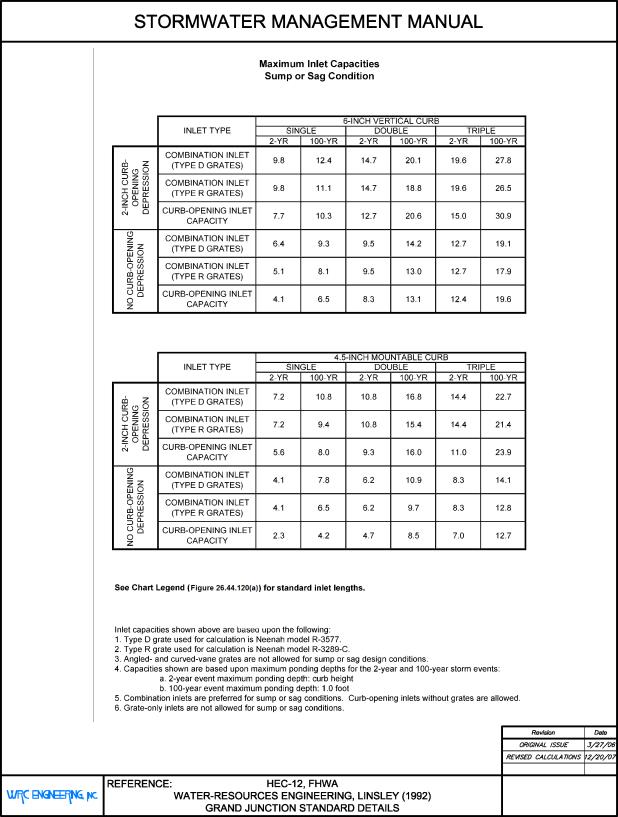
Local inlet depression increases the capacity of inlets, especially those in sumps, by increasing the depth over the inlet without increasing street flow depth. Local depression loses effectiveness for curb-opening inlets of 12-foot length or greater, so the “Curb-Opening” information from Table 28.44.130 shall be used for these. Figure 28.44.130 contains two tables with maximum inlet capacities for inlets with a two-inch local depression and without depression (level with curb flow line). The first capacity table is for the standard six-inch vertical curb configuration (applies to most streets in Mesa County) and the second table contains values for the 4.5-inch mountable (drive-over) curb. All capacities listed in Figure 28.44.130 include a clogging factor per GJMC 28.44.140.
(Res. 40-08 (§ 1106.2), 3-19-08)
28.44.140 Inlet clogging considerations.
Inlets are always susceptible to clogging when water flows to them. Low flows can carry leaves and finer sediments and deposit them at the inlet, while higher flows can deposit larger debris. The latter is of most concern since it is often too large to be washed down the inlet, even with heavy storm flows. Proper inlet design and timely maintenance including street sweeping, visual inspection of inlets, and removal of large debris are essential to the proper operation of inlets. The clogging factors listed in Table 28.44.140 are based on the assumption that routine maintenance is performed on all drainage structures.
Table 28.44.140 contains the assumed clogging factors for different inlet types. A value of zero percent indicates that no clogging is expected, and a value of 100 percent indicates that the inlet shall be considered completely clogged or is not allowed in the specified conditions.
|
Type of Inlet |
On-Grade |
Sag/Sump d ≤ 0.5 ft. |
Sag/Sump d > 0.5 ft. |
|---|---|---|---|
|
Grate |
50% |
100% |
100% |
|
Curb-Opening |
20% |
20% |
20% |
|
Combination (Grate Portion) |
0% |
0% |
50% |
|
Combination (Curb-Opening Portion) |
100% |
100% |
0% |
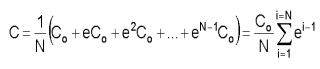
In the case of multiple (double or triple) inlets, the continuous (linear) application of some of these factors would result in the inability to capture 100 percent of the flow incident to the subject inlet. Although on-grade inlets are rarely designed to capture 100 percent of gutter flow from the minor storm event, inlet design lengths may become unnecessarily long to achieve the desired flow interception rate. It is reasonable to assume that a majority of the sediment and debris is deposited at the inlet by the first few minutes of significant storm flow, possibly before the peak flow occurs at that inlet. Also, the majority of clogging tends to more greatly affect the upgradient segments of a multi-unit inlet. For instance, the first grate of a triple inlet may become 50 percent clogged, while the third grate experiences only 10 percent clogging. This phenomenon was generalized by Guo in Design of Grate Inlets with a Clogging Factor (2000) using a decay equation and empirically-derived decay factors. It may be applied to inlets on a continuous grade and inlets in sump conditions.
|
|
(28.44-20) |
Where:
|
C |
= |
Multiple-Unit Clogging Factor (decimal) |
|
Co |
= |
Single-Unit Clogging Factor (decimal) |
|
N |
= |
Number of Units |
|
e |
= |
Decay Ratio |
|
e |
= |
0.5 for grates, 0.25 for curb-opening inlets |
This adjusted clogging factor can be applied to the sump-inlet capacity equations (Equations 28.44-18 and 28.44-19) by replacing the variables for weir length Lw with effective weir length (Lwe) from Equation 28.44-21 and orifice area Ao with effective opening area (Aoe) from Equation 28.44-22. The clogging factor may also be applied directly to the gross flow capacities from Equations 28.44-18 and 28.44-19 using Equation 28.44-23.
|
|
(28.44-21) |
|
|
(28.44-22) |
|
|
(28.44-23) |
To apply the clogging factor to an on-grade inlet, the designer must first find the effective length (Le) – that portion of the inlet length which is considered unclogged.
|
|
(28.44-24) |
This value is used in the computation of splash-over velocity in Equation 28.44-10, side-flow interception ratio in Equation 28.44-12, and curb-opening efficiency in Equation 28.44-17.
(Res. 40-08 (§ 1106.3), 3-19-08)
28.44.150 Grate selection and rating.
Selection of grates for on-grade and sump inlets must be consistent with GJMC 28.44.120(a) and the page titled “Approved Storm Drain Inlets” (D-05) of the City of Grand Junction Standard Details. The designer is urged to obtain any grate rating data available from the manufacturer of the selected grate. This data may be used to cross-check the values obtained using the methods presented in this manual and/or to obtain interception and capacity values. However, in the latter case, it is imperative that the designer still incorporate all clogging/safety factors that apply to the inlet design per local jurisdictions’ requirements.
(Res. 40-08 (§ 1106.4), 3-19-08)
28.44.160 Inlet location and spacing.
Inlets shall be placed at any location where ponding water may encroach on street traffic beyond the allowable limits. These limits are defined by gutter flow depth during the minor storm event (GJMC 28.44.090). An inlet location is determined using an iterative process:
(a) Determine a preliminary location for the inlet based on street configuration and estimated runoff to the gutter.
(b) If the inlet is in a sump, location is essentially fixed during the remainder of the design process. The inlet shall be sized to maintain ponding depths smaller than those required by local jurisdictions. If the required inlet size becomes excessively large, the designer is urged to install additional inlets upgradient from the sump.
(c) For inlets on a grade, the designer must find the flow characteristics at the selected preliminary inlet location to determine whether the inlet needs to be placed further upstream or may be moved downstream based on maximum flow depth for the minor storm event.
(d) The designer shall take into account the change in tributary area to the inlet associated with any upstream or downstream movement.
(e) A typical design interception efficiency of an on-grade inlet is 70 to 80 percent. As mentioned previously, on-grade inlets designed to capture 100 percent of the minor storm runoff tend to be significantly less effective both hydraulically and economically.
(f) The designer shall include any carryover (bypass) flow from an upstream inlet when calculating the flow at a downstream inlet. Although the peak runoff to an inlet may not coincide with the peak carryover flow from an upstream inlet, these two peak flows shall be added to find the total peak flow to the downstream inlet.
Maximizing the use of sump inlets tends to increase the overall efficiency of the inlet system, and inlets must be installed at all street sags (vertical curve low points) and at all sumps formed by intersections except where other drainage provisions have been made. Therefore, it is suggested that sump inlets are located prior to the placement of any on-grade inlets during the design process.
(Res. 40-08 (§ 1106.5), 3-19-08)