Chapter 4
TRANSPORTATION
Chapter 4
4A GENERAL STANDARDS
4A.010 General
4B STREETS
4B.010 General
4B.020 Design Standards
4B.030 Functional Classification
4B.035 Commercial Collectors
4B.040 Naming
4B.050 Signing and Striping
4B.060 Right-of-Way
4B.070 Private Streets
4B.080 Streetside (Frontage) Improvements
4B.085 StreetSide (Frontage) Improvements West Bay Drive
4B.090 Streetside (Frontage) Improvements Boulevard Road (Standard Drawing 4-2G8)
4B.095 Streetside (Frontage) Improvements East Downtown
4B.110 Half Street
4B.120 Medians
4B.130 Intersections
4B.140 Driveways
4B.150 Sight Obstructions at Intersections
4B.160 Surfacing Requirements
4B.170 Temporary Street Patching
4B.175 Pavement Restoration
4B.180 Trench Backfill
4B.190 Surveying and Staking
4B.195 Utility Coordination
4B.200 Testing
4B.210 Traffic Calming Devices
4C SIDEWALKS AND CURBS
4C.020 Design Standards
4C.030 Sidewalks
4C.040 Curb or Curb and Gutter
4C.050 Curb Ramps
4C.060 Staking
4C.070 Parking Bulb-outs
4C.071 Pedestrian Bulb-outs
4D BIKEWAYS
4D.020 Design Standards
4D.030 Staking and Testing
4E TRAILS OR SHARED-USE PATHS
4E.010 Design Standards
4E.020 Pathway Illumination
4F ILLUMINATION
4F.010 General
4F.020 Design Standards
4F.030 Technical Requirements for Streetlight Construction
4F.040 Staking
4F.050 Testing
4G SIGNALS
4G.010 General
4G.020 Design Standards
4G.030 Induction Loops
4G.040 Staking
4G.050 Testing
4G.060 Checkout Procedures
4H MISCELLANEOUS STREETSIDE FEATURES
4H.010 General
4H.020 Design Standards
4H.030 Surveying and Staking
4H.040 Testing
4H.050 Survey Monuments
4H.060 Bus Stops and Amenities
4H.070 Mailboxes
4H.080 Guardrails
4H.090 Retaining Walls
4H.100 Street Trees
4H.110 Parking Lots
4H.120 Parking Meters
4H.130 Crosswalks
4I ACCESS POINTS AND INTERSECTION CRITERIA
4I.010 General
4I.020 Applicability
4I.030 Methods of Measurements
4I.040 Spacing of Access Points, Same Side of Street
4I.050 Alignment of Offset of Cross-Street Access Points
4I.060 Corner Clearance from Intersections
4I.070 Number of Access Points
4I.080 Access Location Based on Street Class
4I.090 Combined or Shared Access
4I.100 Direction of Driveways (One-Way or Two-Way)
4I.110 Adjustment for Street Gradient
4I.120 Drive-Through Windows
4I.130 Monitoring and Enforcement
4I.140 Design of Access Points and Driveways
Appendix 1: List of Standard Drawings
Appendix 2: Index of Tables
Appendix 3: Monument Preservation Documentation Letter
Appendix 4: Downtown Boundaries
Appendix 5: Transportation Related Special Provisions
Appendix 6: Pervious Concrete Sidewalk Construction Standards
Appendix 7: Traffic Impact Analysis (TIA) Guidelines for New Developments
4A GENERAL STANDARDS
4A.010 General
The intent of this chapter is to encourage the uniform development of an integrated and accessible public street system that will support present and future multi-modal transportation.
Through the implementation of these standards, streets are built as transportation facilities as well as public spaces, contributing positively to the character of an area. These standards help create an efficient multi-modal transportation system with minimal environmental impact to the community.
These standards balance the safety and mobility of motor vehicles, bicyclists, pedestrians and transit riders. The features in the standards are intended to: maintain safe motor vehicle speeds through narrow street widths and street edge features for friction; provide safe pedestrian crossings through narrow lane widths, crossing islands, and curb bulb-outs; provide inviting space for pedestrians on wide sidewalks with buffers from motor vehicle traffic; provide adequate width, signs and markings for safe on-street bicycle travel, and; create inviting public space through landscaping and other street edge treatments.
This chapter provides minimum development standards supplementing the applicable standards as set forth.
Deviations as defined in Chapter 1 shall be considered by the City Engineer as outlined in Chapter 1, Section 1.050. A request for deviation increasing the 10' travel lane width for Arterial and Major Collector streets shall be based upon the following criteria:
• High frequency transit route as defined by 15 minute transit service frequency on any given day.
• High frequency truck traffic where trucks compose 5 percent or more of the total daily traffic.
• The roadway alignment includes a unique curve of 200 foot radius or less.
• The geometry of the roadway includes a skewed intersection.
4B STREETS
4B.010 General
Design and construction of City streets shall meet the standards in this and other relevant sections of this Chapter. Table 1 lists all Arterials and Major Collectors, and the number of lanes required for each street section listed. Table 2 summarizes the Street Design Standards and Table 3 summarizes other Street Characteristics to be considered and/or addressed.
4B.020 Design Standards
The design of streets and roads will depend upon their type and usage. The design elements of city streets will conform to City standards as set forth herein, to safely and uniformly accommodate maximum anticipated loading conditions.
The layout of streets will provide for the continuation of existing streets in adjoining subdivisions or of their proper projection when adjoining property is not subdivided.
A. Alignment. Alignment of major arterials, minor arterials, and collectors will conform as nearly as possible with that shown in the Comprehensive Plan.
B. Grade. Street grade should conform closely to the natural contour of the land. In some cases a different grade may be required by the City Engineer. The minimum allowable grade will be 0.5 percent. The maximum allowable grade will be 8 to 15 percent, depending upon the street classification.
C. Width. The pavement and right-of-way width depend upon the street classification. Table 2, Street Design Standards, shows the minimum widths allowed.
Street widths will be measured as shown on Standard Drawings for each street classification.
D. The General Notes for Street Construction listed on Drawing 3-1 shall be included on any plans dealing with street, sidewalk and/or pathway design as applicable.
E. Low Impact Development. As part of meeting the DDECM’s LID-related requirements, bioretention swales may be allowed under certain conditions outlined in the DDECM, as amended and updated. Standard street sections for those street classifications allowing bioretention swales are indicated in the Standard Drawings that have a drawing number ending in “-LID”. Swale details, including planting requirements, can be found in Chapter 5 of the EDDS
4B.030 Functional Classification
City streets are divided into Arterial, Major Collector, Neighborhood Collector, and Local Access street classifications. The City Council has the authority to classify or reclassify all streets, in accordance with regional transportation needs and the functional use each serves. Definitions for each of these street classifications can be found in section 2.020 of these Standards.
4B.035 Commercial Collectors
The Commercial Collector Street standard in Table 2 apply to (1) all streets in the Downtown area (see Appendix 4), as well as commercially-zoned areas of the City that are not Arterials. Commercial Collector Streets shall be constructed or reconstructed to the Commercial Collector street standard, as detailed in Table 2 and Standard Drawings 4-2D, 4-2E, 4-2E-LID1, 4-2E-LID2 and 4-2G10. Commercial Collector streets shall include bike lanes as they apply to Major Collectors and Neighborhood Collectors (refer to Section 4D, Bikeways, for guidance.
|
Region Section |
Street Name |
From |
To |
Class |
Required Lanes (1) |
Street Classification (2) |
|---|---|---|---|---|---|---|
|
DT |
4th Avenue |
Olympic Way |
Water Street |
Arterial |
4/5 |
Existing Arterial |
|
DT |
4th Avenue |
Water Street |
Chestnut Street |
Arterial |
2 |
Existing Arterial |
|
NS |
4th Avenue |
Chestnut Street |
Pacific Avenue |
Arterial |
3 |
Existing Arterial |
|
NS |
4th Avenue |
Pacific Avenue |
Phoenix Street |
Arterial |
5 |
Existing Arterial |
|
DT |
14th Avenue |
Capitol Way |
I-5 |
Arterial |
4/5 |
Existing Arterial |
|
DT |
Adams Street |
State Avenue |
8th Street |
Arterial |
2 |
Existing Arterial |
|
WS |
Black Lake Boulevard |
US 101 |
21st Avenue |
Arterial |
5 |
Existing Arterial |
|
WS |
Black Lake Boulevard |
21st Avenue |
South City Limits |
Arterial |
4/5 |
Existing Arterial |
|
WS |
Black Lake Boulevard |
Cooper Point Road |
US 101 |
Arterial |
5 |
Widening of Existing Arterial |
|
WS |
Black Lake Boulevard |
4th Avenue |
Cooper Point Road |
Arterial |
4/5 |
Existing Arterial |
|
DT |
Boston Harbor Road |
North City Limits |
Ames Road |
Arterial |
2 |
Existing Major Arterial |
|
SS |
Capitol Boulevard |
Capital Way |
Carlyon Avenue |
Arterial |
4 |
Existing Arterial |
|
DT |
Capitol Way |
Corky Avenue |
Capitol Boulevard |
Arterial |
4 |
Existing Arterial |
|
WS |
Cooper Point Road |
Conger Avenue |
Evergreen Park Drive |
Arterial |
5 |
Existing Arterial |
|
WS |
Cooper Point Road |
Evergreen Park Drive |
US 101 |
Arterial |
5 |
Widening of Existing Arterial |
|
WS |
Cooper Point Road |
28th Street |
Conger Avenue |
Arterial |
2/3 |
Widening of Existing Arterial |
|
WS |
Division Street |
14th Avenue |
Garfield Avenue |
Arterial |
2/3 |
Existing Arterial |
|
WS |
Division Street |
Garfield Avenue |
4th Avenue |
Arterial |
4/5 |
Existing Arterial |
|
NS |
East Bay Drive |
Ames Road |
San Francisco Avenue |
Arterial |
2/3 |
Existing Arterial |
|
NS |
East Bay Drive |
San Francisco Avenue |
State Avenue |
Arterial |
3 |
Existing Arterial |
|
WS |
Harrison Avenue |
Cushing Street |
Olympic Way |
Arterial |
4/5 |
Existing Arterial |
|
WS |
Harrison Avenue |
Cooper Point Road |
Cushing Street |
Arterial |
4/5 |
Existing Arterial |
|
WS |
Harrison Avenue |
West City Limits |
Cooper Point Road |
Arterial |
4/5 |
Widening of Existing Arterial |
|
DT |
Henderson Boulevard |
Plum Street |
I-5 |
Arterial |
4/5 |
Existing Arterial |
|
SS |
Henderson Boulevard |
I-5 |
North Street |
Arterial |
2/3 |
Existing Arterial |
|
DT |
Jefferson Street |
8th Avenue |
Maple Park Avenue |
Arterial |
4/5 |
Existing Arterial |
|
NE |
Martin Way |
Phoenix Street |
Devoe Street |
Arterial |
5 |
Existing Arterial /Future Turn Lane |
|
NE |
Martin Way |
Devoe Street |
Lilly Road |
Arterial |
4 |
Addition RW for Median Island |
|
NE |
Martin Way |
Lilly Road |
College Street |
Arterial |
5 |
|
|
WS |
Mud Bay Road |
West UGB |
West City Limits |
Arterial |
4/5 |
Widening of Existing Arterial |
|
WS |
Olympic Way |
4th Avenue Bridge |
Harrison Avenue |
Arterial |
4 |
Existing Arterial |
|
NE |
Pacific Avenue |
State Avenue |
I-5 Overpass |
Arterial |
4/5 |
Existing Arterial |
|
SS |
Pacific Avenue |
I-5 |
East City Limits |
Arterial |
4/5 |
Existing Arterial |
|
SS |
Pacific Avenue |
East City Limits |
East UGB |
Arterial |
4/5 |
Existing Arterial |
|
DT |
Plum Street |
State Avenue |
Henderson Boulevard |
Arterial |
4/5 |
(1) Existing Arterial |
|
NE |
Sleater-Kinney Road |
I-5 |
Martin Way |
Arterial |
4/5 |
Existing Arterial |
|
DT |
State Avenue |
Wilson Street |
Water Street |
Arterial |
2 |
Existing Arterial, Potential HOV |
|
DT |
Union Avenue |
Capitol Way |
Plum Street |
Arterial |
4/5 |
Existing Arterial |
|
DT |
Union Avenue |
Plum Street |
Eastside Street |
Arterial |
4/5 |
Existing Arterial |
|
DT |
Water Street |
State Avenue |
4th Avenue |
Arterial |
3 |
Existing Arterial |
|
WS |
Yauger Way Extension |
SR 101/Black Lake Boulevard |
Capital Mall Drive |
Arterial |
2/3 |
Future Arterial |
|
SS |
Yelm Highway |
Henderson Boulevard |
Rich Road |
Arterial |
4/5 |
Existing Arterial |
|
WS |
4th Avenue |
Kenyon Street |
Olympic Way |
Major Collector |
2 |
Existing Major Collector |
|
DT |
5th Avenue |
4th Avenue/Olympic Way |
Water Street |
Major Collector |
4 |
Existing Major Collector |
|
NS |
5th Avenue |
Water Street |
Eastside Street |
Major Collector |
2/3 |
Existing Major Collector |
|
WS |
7th Avenue |
Kaiser Road |
McPhee Road |
Major Collector |
2/3 |
Existing Major Collector |
|
DT |
8th Avenue |
Capitol Way |
Eastside Street |
Major Collector |
2/3 |
Existing Major Collector |
|
WS |
9th Avenue |
Black Lake Boulevard |
Decatur Road |
Major Collector |
2/3 |
Existing Major Collector |
|
DT |
11th Avenue |
Capitol Way |
Jefferson Street |
Major Collector |
2 |
Existing Major Collector w/ Center Median |
|
NE |
12th Avenue |
Wilson Street |
Fenske Drive |
Major Collector |
2/3 |
Existing Major Collector |
|
NE |
12th Avenue |
South Bay Road |
City Limits |
Major Collector |
2/3 |
Additional RW for New Major Collector |
|
NE |
12th Avenue |
PSP Hospital |
Sleater-Kinney Road |
Major Collector |
2/3 |
Additional RW for New Major Collector |
|
WS |
14th Avenue |
Kaiser Road |
Division Street |
Major Collector |
2/3 |
Existing Major Collector |
|
SS |
14th Avenue |
Elizabeth Street |
East City Limits |
Major Collector |
2/3 |
Existing Major Collector/Future Left-Turn Needs |
|
SS |
18th Avenue |
Wilson Street |
Elizabeth Street |
Major Collector |
2/3 |
Existing Major Collector |
|
WS |
20th Avenue |
Road Sixty-Five |
Crestline Boulevard |
Major Collector |
2/3 |
Existing Major Collector |
|
WS |
20th Avenue |
Kaiser Road |
Road Sixty-Five |
Major Collector |
2/3 |
Future Major Collector |
|
WS |
21st Avenue |
Black Lake Boulevard |
R.W. Johnson Boulevard |
Major Collector |
2/3 |
(2) Existing Major Collector |
|
SS |
22nd Avenue |
Eastside Street |
Boulevard Road |
Major Collector |
2/3 |
Existing Major Collector |
|
NE |
26th Avenue |
South Bay Road |
Pleasant Glade Road |
Major Collector |
2/3 |
Existing Major Collector |
|
NE |
26th Avenue |
Gull Harbor Road |
South Bay Road |
Major Collector |
2/3 |
Existing Major Collector |
|
SS |
27th Avenue |
Wiggins Road |
Hoffman Road |
Major Collector |
2/3 |
Existing Major Collector |
|
WS |
28th Avenue |
Division Street |
West UGB |
Major Collector |
2/3 |
Existing Major Collector |
|
NE |
Ames Road |
East Bay Drive |
North City Limits |
Major Collector |
2 |
Existing Major Collector |
|
NE |
Bethel Street |
26th Avenue |
San Francisco Avenue |
Major Collector |
2 |
Existing Major Collector |
|
WS |
Birch/Bing Street |
Harrison Avenue |
4th Avenue |
Major Collector |
2/3 |
Future Major Collector |
|
NE, SS |
Boulevard Road |
Pacific Avenue |
Yelm Highway |
Major Collector |
2/3 |
Major Collector Medians (See Table 5) |
|
SS |
Cain Road |
22nd Avenue |
Log Cabin Road |
Major Collector |
2/3 |
Existing Major Collector |
|
WS |
Capital Mall Drive |
McPhee Road |
Black Lake Boulevard |
Major Collector |
4 |
Existing Major Collector |
|
SS |
Carlyon Avenue |
Capitol Boulevard |
Henderson Boulevard |
Major Collector |
2/3 |
Existing Major Collector |
|
WS |
Carriage Loop |
Carriage Street |
Carriage Drive |
Major Collector |
2/3 |
Existing Major Collector |
|
WS |
Carriage Street |
Cooper Point Road |
Carriage Drive |
Major Collector |
2/3 |
Existing Major Collector |
|
WS |
Caton Way |
Cooper Point Road |
Decatur Street (at south end of trail) |
Major Collector |
2/3 |
Existing Major Collector |
|
NE |
Central Street |
Bigelow Avenue |
11th Avenue |
Major Collector |
2 |
Existing Major Collector |
|
WS |
Conger Avenue |
Harrison Avenue |
Cooper Point Road |
Major Collector |
2/3 |
Future Major Collector |
|
WS |
Conger Avenue |
Cooper Point Road |
Division Street |
Major Collector |
2/3 |
Existing Major Collector |
|
WS |
Cooper Point Road |
North UGB |
28th Street |
Major Collector |
2/3 |
Existing Major Collector |
|
WS |
Crestline Boulevard |
Elliot Avenue |
Raft Avenue |
Major Collector |
2 |
Existing Major Collector |
|
DT |
D Avenue |
Capitol Way |
Franklin Street |
Major Collector |
2/3 |
Existing Major Collector |
|
WS |
Decatur Street |
Harrison Avenue |
9th Avenue |
Major Collector |
2 |
Existing Major Collector |
|
WS |
Decatur Street |
9th Avenue |
1700 Block |
Major Collector |
2 |
Existing Major Collector |
|
WS |
Deschutes Parkway |
5th Avenue |
South City Limits |
Major Collector |
2/3 |
Major Collector |
|
WS |
Division Street |
28th Avenue |
14th Avenue |
Major Collector |
2/3 |
Existing Major Collector |
|
SS |
Eastside Street |
State Avenue |
22nd Avenue |
Major Collector |
2/3 |
Existing Major Collector |
|
SS |
Elizabeth Street |
18th Avenue |
14th Avenue |
Major Collector |
3 |
Existing Major Collector |
|
NE |
Ensign Road |
Martin Way |
Lilly Road |
Major Collector |
2/3 |
Existing Major Collector |
|
NE |
Ensign Road |
Pacific Avenue |
Martin Way |
Major Collector |
2/3 |
Future Major Collector |
|
SS |
Eskridge Boulevard |
O’Farrell Avenue |
Cain Road |
Major Collector |
2/3 |
Existing Major Collector |
|
WS |
Evergreen Park Drive |
Cooper Point Road |
Lakeridge Drive |
Major Collector |
2/3 |
Future Major Collector |
|
NS |
Fir Street |
Legion Way |
Pine Street |
Major Collector |
2 |
Future Major Collector |
|
SS |
Fones Road |
1400 Block Fones Road |
18th Avenue |
Major Collector |
3 |
Widening of Existing Major Collector |
|
SS |
Fones Road |
Pacific Avenue |
1400 Block Fones Road |
Major Collector |
4/5 |
Widening of Existing Major Collector |
|
NE |
Friendly Grove Road |
North UGB |
26th Avenue |
Major Collector |
2 |
Existing Major Collector |
|
NE |
Friendly Grove Road |
26th Avenue |
Miller Avenue |
Major Collector |
2 |
Existing Major Collector |
|
NE |
Gull Harbor Road |
North UGB |
North City Limits |
Major Collector |
2/3 |
Existing Major Collector |
|
SS |
Henderson Boulevard |
North Street |
Yelm Highway |
Major Collector |
2/3 |
Existing Major Collector |
|
SS |
Herman Road |
Wiggins Road |
East City Limits |
Major Collector |
2/3 |
Future Major Collector Boulevard |
|
SS |
Hoffman Road |
18th Avenue |
Morse-Merrymann Road |
Major Collector |
2/3 |
Existing Major Collector |
|
SS |
Hoffman Road |
Morse-Merryman Road |
Log Cabin Road Connection |
Major Collector |
2/3 |
Future Major Collector |
|
SS |
Hoffman Road Realignment |
Fones Road/Hoffman Road |
Fones Road/Elizabeth Avenue |
Major Collector |
2/3 |
Future Major Collector |
|
WS |
Kaiser Road |
16th Lane SW |
Black Lake Boulevard |
Major Collector |
2/3 |
Future Major Collector |
|
WS |
Kaiser Road |
Evergreen College Parkway |
Cooper Point Road |
Major Collector |
2/3 |
Existing Major Collector |
|
WS |
Kaiser Road |
North UGB |
16th Lane SW |
Major Collector |
2/3 |
Existing Major Collector |
|
WS |
Kenyon Street |
Harrison Avenue |
4th Avenue |
Major Collector |
4 |
Existing Major Collector |
|
WS |
Lakeridge Drive |
Deschutes Parkway |
Evergreen Park Drive |
Major Collector |
2/3 |
Future Major Collector |
|
DT |
Legion Way |
Water Street |
Plum Street |
Major Collector |
2/3 |
Existing Major Collector |
|
NS |
Legion Way |
Plum Street |
Fir Street |
Major Collector |
2 |
Existing Major Collector |
|
NE |
Lilly Road |
North UGB |
15th Avenue |
Major Collector |
2/3 |
Existing Major Collector |
|
NE |
Lilly Road |
15th Avenue |
Martin Way |
Major Collector |
4 |
Existing Major Collector |
|
NE |
Lilly Road |
Martin Way |
I-5 Overpass |
Major Collector |
4/5 |
Existing Major Collector |
|
SS |
Lilly Road |
I-5 |
Pacific Avenue |
Major Collector |
4/5 |
Existing Major Collector |
|
SS |
Log Cabin Road |
Cain Road |
Boulevard Road |
Major Collector |
2/3 |
Existing Major Collector |
|
SS |
Log Cabin Road Connections |
Boulevard Road |
Major Collector |
2/3 |
Future Major Collector Boulevard |
|
|
WS |
McPhee Road |
Harrison Avenue |
7th Avenue / Capital Mall |
Major Collector |
2/3 |
Existing Major Collector |
|
DT |
Marine Drive |
Market Street |
Olympia Avenue |
Major Collector |
2/3 |
Existing Major Collector |
|
DT |
Market Street |
Capitol Way |
Marine Drive |
Major Collector |
2/3 |
Existing Major Collector |
|
NE |
Miller Avenue |
Bethel Street |
Friendly Grove Road |
Major Collector |
2 |
Existing Major Collector |
|
SS |
Morse-Merryman Road |
Boulevard Road |
Wiggins Road |
Major Collector |
2/3 |
Existing Major Collector |
|
WS |
Mottman Road |
R.W. Johnson Boulevard |
Crosby Boulevard |
Major Collector |
2/3 |
Existing Major Collector/Future Left-Turn Needs |
|
SS |
North Street |
West City Limits |
Cain Road |
Major Collector |
2/3 |
Existing Major Collector/Future Left-Turn Needs |
|
SS |
O’Farrell Avenue |
Capitol Boulevard |
Eskridge Boulevard |
Major Collector |
2 |
Existing Major Collector |
|
NS |
Olympia Avenue |
Jefferson Street |
East Bay Drive |
Major Collector |
2/3 |
Existing Major Collector |
|
NE |
Pattison Street |
Martin Way |
Pacific Avenue |
Major Collector |
2/3 |
Future Major Collector |
|
NS |
Phoenix Street |
South Bay Road |
Pacific Avenue |
Major Collector |
2/3 |
Existing Major Collector |
|
NE |
Pine Avenue |
Puget Street |
Wilson Street |
Major Collector |
2 |
Existing Major Collector |
|
NE |
Providence Lane |
12th Avenue |
Ensign Road |
Major Collector |
2/3 |
Future Major Collector |
|
NE |
Puget Street |
San Francisco Avenue |
State Avenue |
Major Collector |
2/3 |
Existing Major Collector |
|
WS |
Raft Avenue |
Crestline Boulevard |
Schneider Hill Road |
Major Collector |
2 |
Existing Major Collector |
|
WS |
Road Sixty-Five |
20th Avenue |
14th Avenue |
Major Collector |
2 |
Existing Major Collector |
|
WS |
Road Sixty-Five Connector |
28th Avenue |
Road Sixty-Five |
Major Collector |
2/3 |
Future Major Collector |
|
WS |
Rogers Street |
Bowman Avenue |
4th Avenue |
Neighborhood Collector |
2 |
Existing Neighborhood Collector |
|
WS |
R.W. Johnson Boulevard |
Mottman Road |
21st Avenue |
Major Collector |
2/3 |
Existing Major Collector |
|
NE |
San Francisco Avenue |
East Bay Drive |
Bethel Street |
Major Collector |
2/3 |
Existing Major Collector |
|
WS |
Schneider Hill Road |
West Bay Drive |
Raft Avenue |
Major Collector |
2 |
Existing Major Collector |
|
DT |
Simmons Street |
5th Avenue |
4th Avenue |
Major Collector |
2/3 |
Existing Major Collector |
|
NE |
Sleater-Kinney Road |
North UGB |
6th Avenue |
Major Collector |
2/3 |
Existing Major Collector/Future Left-Turn Needs |
|
NS |
Sleater-Kinney Road |
6th Avenue |
Martin Way |
Major Collector |
4/5 |
Existing Major Collector |
|
NE |
South Bay Road |
Steele Street |
North UGB |
Major Collector |
2 |
Existing Major Collector |
|
NE |
State Avenue |
Pacific Avenue |
Steele Street |
Major Collector |
2 |
Existing Major Collector |
|
SE |
Stoll Road |
Lilly Road |
“North-South” Stoll Road |
Major Collector |
2 |
Existing Major Collector |
|
SE |
Stoll Road (North-South part) |
Stoll Road “T” |
Martin Way |
Major Collector |
2 |
Future Major Collector |
|
DT |
Thurston Avenue |
Capitol Way |
Jefferson Street |
Major Collector |
2/3 |
Existing Major Collector |
|
WS |
West Bay Drive |
Harrison Avenue |
Schneider Hill Road |
Major Collector |
2/3 |
Existing Major Collector Modified |
|
SS |
Wheeler Street |
Eastside Street |
Boulevard Road |
Major Collector |
2 |
Existing Major Collector |
|
SS |
Wiggins Road |
27th Avenue |
Yelm Highway |
Major Collector |
2/3 |
Existing Major Collector |
|
NE |
Wilson Street |
12th Avenue |
Pine Avenue |
Major Collector |
2 |
Existing Major Collector |
|
SS |
Wilson Street |
18th Avenue |
22nd Avenue |
Major Collector |
2/3 |
Existing Major Collector |
|
WS |
Yauger Way |
Harrison Avenue |
Forestbrooke Way |
Major Collector |
2/3 |
Existing Major Collector |
(1) If 2/3 or 4/5 lanes are indicated, left-turn channelization may be required for vehicle capacity or safety needs.
(2) For the location of each street, see the Transportation 2030 Maps in Appendix B of the Transportation section of the Comprehensive Plan.
|
Design Standards |
Functional Classification |
|||||||||||
|---|---|---|---|---|---|---|---|---|---|---|---|---|
|
|
Arterial Blvd |
Arterial |
Major Industrial Collector |
Commercial Collector Blvd |
Commercial Collector |
Major Collector Blvd |
Major Collector |
Neighbor-hood Collector Blvd |
Neighborhood Collector |
Local Access |
||
|
|
|
|
|
|
|
|
|
|
|
|
Com. |
Res |
|
Minimum Structural Design |
See Standard Drawing 4-6A |
|||||||||||
|
ADT |
14,000-40,000 |
14,000-40,000 |
3,000-14,000 |
3,000-14,000 |
3,000-14,000 |
3,000-14,000 |
3,000-14,000 |
500-3,000 |
500-3,000 |
0-500 |
N/A |
N/A |
|
Sidewalks |
8' both sides (1)(10) |
8' both sides (1)(10) |
6' both sides (1) |
10' Both sides (10) |
10' Both sides (10) |
6' both sides |
6' both sides |
5' both sides |
5' both sides |
5' both sides |
None |
None |
|
Planting Strips (4) |
10' between curb & walk both sides ----- 14' center median |
10' between curb & walk both sides |
6' between curb & walk both sides |
2-lane = 10' median ----- 4-lane = 14' median |
4-ft in sidewalk adjacent to curb |
8' between curb & walk both sides ----- 14' center median |
8' between curb & walk both sides |
8' between curb & walk both sides (2) ----- 10' median |
8' between curb & walk both sides (2) |
8' between curb & walk both sides (2) |
None |
None |
|
Street Tree Spacing (5) |
40' on center |
40' on center |
40' on center |
40' on center (9)(10) |
40' on center (9)(10) |
40' on center |
40' on center |
40' on center |
40' on center |
40' on center |
None |
None |
|
Parking Lanes |
None (12) |
None |
None |
8' both sides |
8' both sides |
None |
None |
None |
7' one side |
7' one side (6) |
None |
None |
|
Curbs |
Curb both sides |
Curb both sides |
Curb both sides |
Curb both sides |
Curb both sides |
Curb both sides |
Curb both sides |
Curb both sides |
Curb both sides |
Curb both sides |
None |
None |
|
Lane Widths |
All Arterials and Major Collectors will use 10-foot travel lanes, 5-foot bike lanes and 11-foot center turn lanes. On high frequency bus routes and truck routes, upon evaluation, the City Engineer may require different lane width dimensions to address safety concerns. Street widths will be measured as shown on Standard Drawings for each street classification. |
2 lane - 1'-6' |
1 lane-10' 1 lane-9' |
1 lane-12' |
12 |
Two-36" ribs |
||||||
|
Street widths will be measured as shown on Standard Drawings for each street classification.
|
||||||||||||
|
R-O-W |
2 lanes - 88' 3 lanes - 88' 4 lanes - 104' 5 lanes - 104' |
2 lanes - 68 ’3 lanes - 79' 4 lanes - 88' 5 lanes - 99' |
2 lanes - 56' 3 lanes - 67' 4 lanes - 76' 5 lanes - 87' |
2 lanes - 80' 3 lanes - 84' 4 lanes - 104' (3) |
2 lanes - 68' 3 lanes - 79' 4 lanes - 88' (3) |
2 lanes - 80' 3 lanes - 80' 3 lanes - 96' (3) |
2 lanes - 60' 3 lanes - 71' 4 lanes - 80' (3) |
2 lanes - 74' 2 lanes w/ swale - 70' |
2 lanes - 55' - 65' w/ class II and III 2 lanes w/ swale - 51' - 61' w/ class II and III |
1 lane - 48' 1 lane w/ swale - 44' |
12 |
12 No dead ends |
|
Intersect-ion Radii |
35' turning radius (7) |
35' turning radius (7) |
35' turning radius (7) |
35' turning radius (7) |
35' turning radius (7) |
35' turning radius (7) |
35' turning radius (7) |
25' curb radius (7a) |
25' curb radius (7a) |
30' curb radius (7a) |
N/A |
N/A |
|
Cul-de-sac Radii |
N/A |
N/A |
N/A |
N/A |
N/A |
N/A |
N/A |
N/A |
N/A |
47' w/ 22' land-scaped island |
N/A |
N/A |
|
Pedestrian Bulb-outs |
Curb bulb-outs required on all Arterials, Major Collectors, Neighborhood Collectors, Commercial Collectors, and streets in the Downtown, where on-street parking exists. Downtown is defined in Chapter 2, and shown in Appendix 4 of this Chapter. |
|
|
|
||||||||
|
Grades |
0.5-8% |
0.5-8% |
0.5-8% |
0.5-10% |
0.5-10% |
0.5-10% |
0.5-10% |
0.5-12% |
0.5-12% |
0.5-15% |
0.5-15% |
0.5-15% |
|
Maximum Design Speeds |
35 mph |
35 mph |
30 mph |
25 mph |
25 mph |
30 mph |
30 mph |
25 mph |
25 mph |
20 mph |
10 mph |
10 mph |
|
Site Access |
See Access Points and Intersection Criteria Guidelines |
20' from inter-section |
20' from inter-section |
20' from inter-section |
N/A |
N/A |
||||||
|
Street Lighting |
Highmast ornament |
Highmast ornament |
Highmast ornament |
Highmast ornament |
Highmast ornament |
Highmast ornament |
Highmast ornament |
Highmast ornament |
Highmast ornament |
Ped Scale |
N/A |
N/A |
|
Access Width |
See Access Points and Inter-section Criteria Guide-lines |
10' at PL 15' at PL Curb |
10' at PL 15' at PL Curb |
|
10' at PL 15' at PL Curb |
N/A |
N/A |
|
|
|
|
|
|
Bicycle Facilities |
Arterials, Major Collectors and selected Neighborhood Collectors will have Class II bicycle facilities, with the exception of those listed in 4D.020.E. Commercial Collectors shall include bike lanes as they apply to Major Collectors and Neighborhood Collectors (refer to section 4D. Bikeways for guidance). |
N/A |
Class II - only for those listed in 4D.020.E |
N/A |
N/A |
N/A |
||||||
Table Notes:
(1) Sidewalk width will be 10 feet in the Central Business District or where the extensions of existing frontage improvements are being extended and the sidewalk width is 10'.
(2) Swale will only be used as an alternative design based on environmental standards. When swale required, swale width = 12' between curb and sidewalk, 6' tree easement opposite side of swale.
(3) The need for left-turn channelization will be evaluated at intersections and access points.
(4) Unless otherwise agreed upon by the City of Olympia, maintenance of street trees, turf or other landscaping within the planting strips is the responsibility of the adjacent landowner.
(5) Street trees required. Exact spacing and species to be determined by Urban Forester. Spacing is approximate - exact spacing will depend on locations of streetlights, fire hydrants, driveways, sign clearance triangles, etc.
(6) Block faces that are greater than 350 feet require parking bulb-outs at both street ends to define parking with a 100 foot No Parking Zone center block.
(7) Turning radius dimensions represent the vehicle turning path. The smallest curb radius should be used while maintaining the specified turning radius. Lane width and the presence of a bike lane and parking lane affect a vehicle’s turning path and allow a smaller radius to be used. All curb radii shall be designed to accommodate a bus, garbage and fire truck turning path. On streets with more than one lane in that direction of travel, large vehicles may encroach into no more than one-half of the adjacent travel lane to complete the turn. On Arterials and Major Collectors, encroachment into oncoming travel lanes is unacceptable. The minimum curb radius is 15 feet.
(7a) At the intersection of two classes of streets, the radius for the higher class of street is used. Where larger truck types are anticipated, further engineering design will be required to determine an adequate radius.
(8) Parking may be required on a case-by-case analysis of neighborhood parking needs.
(9) Street trees in sidewalk section of Commercial Collector will require street tree frames and grates per Standard Drawing 4-49.
(10) Awnings shall conform to OMC 12.24.020 “Awnings.”
(11) In the Chambers Basin R-4CB zone, all streets shall conform to the local ’full-dispersion’ street standard, per Standard Drawing 4-2JX2.
(12) Exceptions to this include where on-street parking exists on an Arterial Street, where such on-street parking can remain.
|
Street Characteristics |
Arterial Street |
Major Collector |
Neighborhood Collector |
Local Access Street |
|---|---|---|---|---|
|
Types of Traffic Served |
Regional and City-wide |
Sub-regional, feed Arterial traffic |
Local traffic, feed Neighborhood/Major Collector or Arterial Traffic |
|
|
Traffic Volumes |
14,000 - 40,000 Average Daily Traffic |
3,000 - 14,000 Average Daily Traffic |
500 - 3,000 Average Daily Traffic |
0 - 500 Average Daily Traffic |
|
Percent Local Traffic |
0 - 15% of origins and destinations are within a one mile radius of the street |
0 - 30% of origins and destinations are within a one mile radius of the street |
70% - 100% of origins and destinations are within a one mile radius of the street |
80% - 100% of origins and destinations within a one mile radius of the street |
|
Average Travel Length |
10 to maximum miles |
2 to 15 miles |
1 to 2 miles |
Minimum to 2 miles |
|
Street Spacing (1) |
1 - 2 miles |
1/2 - 3/4 mile |
1000' - 1500' |
350' - 500' |
|
Intersection Spacing (2) |
≤500' |
350' - 500' |
250' - 350' |
250' - 350' |
|
Design Speed |
30 - 35 mph |
25 - 35 mph |
25 mph |
20 - 25 mph |
|
On-Street Parking |
No - except where parking exists and where exempt. Existing parking may be removed for other Transportation needs. Where parking exists, intersection bulb-outs are required. |
No - except where parking exists and where exempt. Existing parking may be removed for other Transportation needs. Where parking exists, intersection bulb-outs are required. |
Yes - with bulb-outs at intersections. |
Yes - one side with parking bulb-outs to define parking areas. |
|
Driveway Access |
No |
No - except for existing developments |
Yes |
Yes |
|
Bike Lanes (Class II) |
Yes -See 4D.020.E for exceptions. |
Yes - See 4D.020.E for exceptions. |
Some - See 4D.020.E for exceptions |
No |
|
Planting Strips (between sidewalk and curb) |
Yes |
Yes |
Yes |
Yes |
|
Sidewalks |
Yes |
Yes |
Yes |
Yes |
|
Traffic Calming |
No |
As needed |
Yes - if problem is anticipated or determined through an engineering study. |
Yes - if problem is anticipated or determined through an engineering study. |
|
Transit Shelters |
Every 1/2 mile |
Every 1/2 mile |
None |
None |
|
Transit Pullouts |
Every 1/2 mile |
Every 1/2 mile |
None |
None |
Table 3 Notes:
(1) Street spacing means the frequency of street types within the street network.
(2) Intersection spacing means how often a cross street occurs on a particular class of street.
4B.040 Naming
Streets and roads will be named according to specific criteria. The City is divided into four quadrants by Capitol Way (east or west) and 4th Avenue/ Martin Way (north or south). “Avenues” run east-west and are numbered with the exception of certain long-standing historical names. “Streets” run north-south and are named. “Drives” are irregular or diagonal streets over two grid blocks in length not conforming to the grid pattern. “Places” will be a north-south street parallel to but between streets. “Ways” will be an east-west street parallel to but between avenues. “Courts” will be a cul-de-sac that cannot be extended. Courts are to be named or numbered and carry name or the number of the preceding street or avenue. “Loops” will be small loop-type streets to carry the name of the street from which they originate. “Lanes” will be private streets.
An address number will be assigned to all new buildings at the time the building permit is issued. It is then the owner’s responsibility to see that the house numbers are placed clearly and visibly at the main entrance to the property or at the principal place of ingress.
The developer must check with the Public Works Department regarding the naming of streets. This should be done at the time the preliminary plat is submitted and again upon approval of the final plat. The Public Works Department will ensure that the name assigned to a new street is consistent with policies of the City.
4B.050 Signing and Striping
Street signs are defined as any regulatory, warning, or guide signs. The developer is responsible for providing all street signs. Street signs will comply with the latest edition of the U.S. Department of Transportation Manual on Uniform Traffic Control Devices (MUTCD).
Pavement markings and street signs, including posts and hardware, shall be designed, furnished, installed, and paid for by the developer under the City’s direction. The design and installation of all street signs, pavement markings, and associated hardware, will conform to the Washington State Department of Transportation’s Standard Specifications for Road, Bridge and Municipal Construction, in effect at the time of approval for construction, as modified herein, to establish and maintain uniformity.
Plastic pavement markings (preformed tape or sprayed application) shall be used for all transverse, long line, and symbol markings unless otherwise approved by the City Engineer.
Street name signs will display street names, district designation, and grid numbers.
Mast arm street name signs will be pursuant to Standard Drawing 4-37. Post-mounted signs will be pursuant to Standard Drawing 4-45.
4B.060 Right-of-Way
Right-of-way is determined by the functional classification of a street. See Table 1. See Drawing Details 4-2A through 4-2L for specific widths. See Table 2 Street Design Standards for radius requirements at cul-de-sac “bulb.” Right-of-way at “bulb” will be increased accordingly.
Right-of-way requirements may be increased if additional lanes, pockets, transit lanes, bus loading zones, operational speed, bike lanes, utilities, schools, or other factors are required as determined by the Director or Public Works.
Right-of-way will be conveyed to the City on a recorded plat or by a right-of-way dedication or separate instrument.
4B.070 Private Streets
Acceptance as Public Streets. Acceptance of private streets as public streets will be considered only if the streets meet all applicable public street standards, including right-of-way widths.
4B.080 Streetside (Frontage) Improvements
A. All commercial and residential (including multi-family) development, plats, and short plats will install street improvements at the time of construction as required by the Department of Community Planning and Development. Such improvements may include curb and gutter; sidewalk; transit stops, pads, and shelters; street and stormwater; street lighting system; traffic signal modification, relocation, or installation; street trees; utility relocation or installation; undergrounding of franchised utilities; landscaping and irrigation; and street widening, all pursuant to these Standards. Plans will be prepared and signed by a licensed civil engineer registered in the State of Washington.
B. At a minimum, all streetside improvements will be made across the full frontage of the property being developed from centerline to right-of-way line.
Full structural street cross section will be constructed throughout the entire length, including the transition taper. No cross-section taper will be allowed.
C. For Exceptions, see Section 2.040; for Deferrals, see Section 2.070.
D. When streetside improvements are required:
1. Half-street pavement reconstruction will be required when the existing pavement rating is at or below 40, based on the City of Olympia Pavement Management System; crown slope is greater than 3 percent; is light bituminous pavement; and/or was built with no base structure. Section pavement coring and/or subsurface investigation will be required to determine base condition.
2. Half-street asphalt overlay (2-inch minimum) will be required when the existing pavement rating is at or below 60 based on the City of Olympia Pavement Management System. Pre-leveling may be required to create a uniform 2 percent crown slope.
4B.085 Streetside (Frontage) Improvements West Bay Drive
Frontage improvements specific to West Bay Drive will conform to the descriptions contained in Table 4.
|
West Bay Drive Street Section |
Westside of Right-of-Way |
Eastside of Right-of-Way |
|
|---|---|---|---|
|
From |
To |
|
|
|
Roundabouts |
Southern Park Border |
Maintain existing sidewalk location and re-stripe centerline east to provide bicycle lanes north and southbound. (Standard Drawing 4-2G1.) |
Maintain existing sidewalk location and re-stripe centerline east to provide bicycle lanes north and southbound. (Standard Drawing 4-2G1.) Existing on-street parking will be removed. |
|
Southern Park Boundary |
Garfield Nature Trail |
Maintain existing sidewalk location and re-stripe centerline east to provide bicycle lanes north and southbound. (Standard Drawing 4-2G2.) |
Maintain existing sidewalk on the east side of ROW. Re-stripe centerline east to provide bicycle lanes north and southbound. Provide on-street pocket parking/planter. (Standard Drawing 4-2G2.) |
|
Garfield Nature Trail |
Brawne Avenue |
Maintain existing sidewalk location and re-stripe centerline east to provide bicycle lanes north and southbound. (Standard Drawing 4-2G3.) |
Maintain existing sidewalk on the eastside of ROW. Re-stripe centerline east to provide bicycle lanes north and southbound. Bicycle lanes will remain next to the vehicle travel lanes. Sidewalks can be either at street level or below grade. (Standard Drawing 4-2G3.) |
|
Brawne Avenue |
Park Property North Border |
Variable retaining wall, sidewalk and planter strip. (Standard Drawing 4-2G4.) |
The railroad right-of-way will be used for combined trail-sidewalk facility wherever practical and safe. Park trail and sidewalk will be combined in a 10-foot multi-use facility. (Standard Drawing 4-2G4.) |
|
Park Property North Border |
Schneider Hill Base |
Variable retaining wall, sidewalk and planter strip. (Standard Drawing 4-2G5.) |
Bicycle lanes will remain next to the vehicle travel lanes. Sidewalk will be below street grade. If land use remains industrial, trail will be incorporated into the sidewalk. (Standard Drawing 4-2G5.) |
|
Schneider Hill Base |
Schneider Hill Top |
Standard Drawing 4-2G6 |
Standard Drawing 4-2G6. |
|
Schneider Hill Base |
West Bay Marina |
Pocket parking intermixed within planter strip. (Standard Drawing 4-2G7.) |
|
4B.090 Streetside (Frontage) Improvements for Boulevard Road (Standard Drawing 4-2G8)
Table 5 lists the required streetside improvements in various sections of Boulevard Road, working north from Yelm Highway. Refer to Standard Drawing 4-2G8 for more information.
|
From |
To |
Lanes |
|---|---|---|
|
Yelm Highway |
45th Avenue |
2 |
|
45th Avenue |
Boulevard Heights Loop |
3 |
|
Boulevard Heights Loop |
Boulevard Park Court |
2 |
|
42nd Avenue |
41st Way (North Leg) |
2 |
|
Cedar Park Loop (South Leg) |
Cedar Park Loop (North Leg) |
3 |
|
Cedar Park Loop (North of North Leg) |
Log Cabin Road |
2 |
|
Log Cabin Road |
Morse Merryman Road (North Leg) |
2 |
|
31st Avenue (South Leg) |
31st Avenue (North Leg) |
2 |
|
30th Avenue (South Leg) |
31st Avenue (North Leg) |
3 |
|
31st Avenue (North of North Leg) |
28th Avenue (South of South Leg) |
2 |
|
28th Avenue (South Leg) |
28th Avenue (North Leg) |
3 |
|
Fox Avenue (North Leg) |
Swecker Avenue (South of South Leg) |
2 |
|
Swecker Avenue (South Leg) |
Not applicable |
3 |
|
Briar Lea Loop (South Leg) |
Not applicable |
3 |
|
24th Avenue (South Leg) |
24th Avenue (North Leg) |
3 |
|
18th Avenue |
16th Avenue |
2 |
|
Lincoln Avenue (South Leg) |
Not applicable |
2 |
|
15th Avenue (South Leg) |
Not applicable |
2 |
|
Wheeler Avenue (North Leg) |
Not applicable |
2 |
|
9th Avenue (North Leg) |
Not applicable |
2 |
|
7th Avenue (South Leg) |
Not applicable |
2 |
|
The City Engineer will determine locations for median breaks and exclusive left-turn needs. |
||
4B.095 Streetside (Frontage) Improvements East Downtown
|
Street Section |
||
|---|---|---|
|
Cherry Street from 4th Avenue to State Avenue |
• |
Widen sidewalks to 12 feet |
|
• |
Restripe street to a 16-foot one-way lane |
|
|
• |
Maintain parking on both sides |
|
|
• |
Raised mid-block crossing |
|
|
• |
Bulb-outs on corners of 4th Avenue and State Avenue where on street parking exists |
|
|
• |
Stamped colored concrete at crosswalks |
|
|
• |
Underground utilities |
|
|
Chestnut Street from 4th Avenue to State Avenue |
• |
Widen sidewalks to 12 feet |
|
• |
Restripe street to a 16-foot one-way lane |
|
|
• |
Maintain parking on both sides |
|
|
• |
Raised mid-block crossing |
|
|
• |
Bulb-outs on corners of 4th Avenue and State Avenue where on-street parking exists |
|
|
• |
Stamped colored concrete at crosswalks |
|
|
• |
Underground utilities |
|
|
• |
Remove vehicle travel lane, Jefferson to Chestnut (leaving two eastbound lanes), use space for wider parking lanes and bike lane |
|
|
• |
Widen parking lanes to 9 feet |
|
|
• |
Add bike lane on south side of street from Jefferson to Chestnut |
|
|
• |
Rebuild sidewalk, Jefferson to Cherry, retain existing width |
|
|
• |
Add bulb-outs at all corners where on-street parking exists, and extend length of bulb-outs along block faces up to established parking stall |
|
|
• |
Assumes no undergrounding of utilities nor resurfacing, only patching |
|
|
• |
While maintaining south curb line and parking lane, restripe street for two 11-foot travel lanes and a bike lane on the north side |
|
|
• |
Bike lane would extend from Plum to Cherry (no widening required) |
|
|
• |
Relocate 10-foot sidewalk on north side to north edge of right-of-way, provide varying sized planter strip adjacent to relocated parking lane and new bike lane |
|
|
• |
On south side near corner of Plum, widen planter to shadow parking |
|
|
• |
Add bulb-outs on south side at Cherry and at Chestnut where on-street parking exists |
|
|
• |
Widening for bike lane from Cherry to Franklin, with widening |
|
|
• |
Remove travel lane east bound, preserving right turn at Plum |
|
|
• |
Use space for wider sidewalks and bulb-outs at corners and mid-block |
|
|
• |
Widen sidewalks by approximately 5 feet on north and south sides of street |
|
|
• |
Add bulb-outs at corners where on-street parking exists |
|
|
• |
Add mid-block bulb-outs approximately 60 feet long to accommodate larger street trees |
|
|
• |
Remove 1-2 parking stalls for each of 4 mid-block bulb-outs |
|
|
• |
Install large canopy street trees at corners and mid-block |
|
|
• |
Standard street trees in grates |
|
|
• |
Bulb-outs on corners where on-street parking exists |
|
|
• |
Maintain sidewalk width |
|
|
• |
Textured colored concrete in the crosswalks |
|
|
• |
Downtown gateway or entrance signage |
|
4B.110 Half Street
A half street is an otherwise acceptable roadway section modified to conform to limited right-of-way on the boundary of property subject to development. See definition in Chapter 2.
A half street may be permitted, subject to approval by the Public Works Department when:
1. There is reasonable assurance of obtaining the prescribed additional right-of-way from the adjoining property suitable for completion of a full-section roadway; and
2. Such alignment is consistent with or will establish a reasonable circulation pattern; and
3. The right-of-way width of the half street will equal at least 30 feet, or 50 percent of the required right-of-way, whichever is greater; and
4. The traveled way will be surfaced the same as the designated street classification to a width not less than 20 feet; and
5. The half street will be graded consistent with the centerline of the ultimate roadway section; and
6. Property line edge of street will be finished with permanent concrete curb, or curb and gutter to ensure proper drainage, bank stability, and traffic safety.
7. The full street cross-section will be constructed when left-turn channelization, additional vehicle lanes, or medians are required. See Table 2 for design criteria.
4B.120 Medians
A median will be in addition to, not part of, the specified roadway width except on a road classed as a boulevard. Medians will be designed so as not to limit turning radius or sight distance at intersections. Landscaping and irrigation will be installed when directed by the Public Works Director.
For additional guidance on design standards for medians, refer to Section 4I, Access Points and Intersection Criteria.
4B.130 Intersections
A. Traffic control will be as specified in the current edition of the Manual on Uniform Traffic Control Devices (MUTCD) or as modified by the City Engineer as a result of appropriate traffic engineering studies.
B. Street intersections will be laid out so as to intersect as nearly as possible at right angles. Sharp-angled intersections will be avoided. For reasons of traffic safety, a “T” intersection (three-legged) is preferable to a crossroad (four-legged) intersection for local access streets. For safe design, the following types of intersection features should be avoided:
1. Intersection with more than four intersecting streets.
2. “Y”-type intersections where streets meet at acute angles.
3. Intersections adjacent to bridges and other sight obstructions.
4. In no case will the angle of intersection be less than 60 degrees or greater than 120 degrees. The preferred angle of an intersection is 90 degrees.
C. Spacing between adjacent intersecting streets, whether crossing or “T” should be as follows in Table 7.
|
When highest classification involved is: |
Centerline offset should be: |
|
|---|---|---|
|
|
Desirable |
Minimum |
|
Arterial |
≤500 feet |
350 feet |
|
Major Collector |
350-500 feet |
200 feet |
|
Neighborhood Collector |
250-350 feet |
150 feet |
|
Local Access |
250-350 feet |
150 feet |
“Desirable” conditions shall be applied when sufficient space or street frontage is available.
When different class streets intersect, the higher standard will apply on curb radii. Deviations to this may be allowed by the City Engineer per Section 1.050.
D. On sloping approaches at an intersection, landings will be provided with grade not to exceed a 1-foot difference in elevation for a distance of 30 feet approaching any arterial or 20 feet approaching a collector or local access street, measured from the nearest right-of-way line (extended) of intersecting street.
4B.140 Driveways
A. General
This section addresses that portion of the driveway located within the street right of way, also referred to as the driveway approach or entrance. That portion of the driveway located on private property is regulated by Title 18 OMC.
1. Design and construction requirements and details for driveway approaches are located in Table 2 above, section 4I Access Points and Intersection Criteria, and the Standard Drawings appendix of this chapter. Concrete shall be minimum 4,000 psi.
2. All abandoned driveway approaches on the same frontage will be removed and the curb, gutter and sidewalk, or shoulder and ditch section will be properly restored.
3. With the exception of driveway approaches crossing a ditch (with culvert) as detailed in section C below, all driveway approaches will be constructed of impervious Portland Cement Concrete with welded wire fabric reinforcement and will be subject to the same testing and inspection requirements as curb, gutter, and impervious sidewalk construction.
4. Joint-use driveways serving two adjacent parcels may be built on their common boundary upon formal written agreement by both property owners and approval of the City. The agreement will be a recorded easement for both parcels of land specifying joint usage.
5. Grade breaks, including the tie to the street will be constructed as smooth vertical curves. The maximum change in driveway grade will be 8 percent within any 10 feet of distance on a crest and 12 percent within any 10 feet of distance in a sag vertical curve.
6. No commercial driveway approach will be approved where backing onto the sidewalk or street will occur.
B. Arterial and Collector Streets
1. See section 4I, Access Points and Intersection Criteria, for arterial street driveway and access control design criteria.
2. Within the limitations set forth above, access to arterial and collector streets within the City will be limited to one driveway for each tract of property separately owned. Properties contiguous to each other and owned by the same person are considered to be one tract.
3. Driveways giving direct access onto arterial and collector streets may be denied if alternate access is available.
C. Driveway approaches that cross a ditch in the right-of-way (ROW)
For driveway approaches crossing a ditch within the ROW, the culvert under the driveway is to be designed to handle 25-year stormwater flow events in the ditch, of a material designed to handle expected dead and live loads based on depth of cover, and be at least 12 inches in diameter. The culvert pipe shall be beveled and sectioned to match the ditch side slopes, meeting WSDOT Standard Plan B-70.20-00. Driveway material may be asphaltic concrete, and meet the requirements shown in Standard Drawing 4-7F.
4B.150 Sight Obstructions at Intersections
Sight distance standards are important at intersections and driveways so that drivers, bicyclists and pedestrians can see each other, to minimize potential conflicts when approaching and entering these locations. One method to minimize potential conflicts is to require and maintain Clear Sight Triangles.
A. Clear Sight Triangle. The Clear Sight Triangle at each corner of every intersection is a volume of space inside which no permanent obstructions, except those listed in subsection D below, are allowed. The height of this volume of space is between 2.5 feet and 10 feet above the ground surface. The length, or sides, of this triangle will vary by type of intersection, as discussed below, but in no case shall be less than 20 feet on a frontage side, as shown in Standard Drawing 4-1A. Clear Sight Triangle requirements also apply to both sides of commercial driveway approaches.
The area within the Clear Sight Triangle shall be free from all obstructions, except those identified in subsection D below, to maintain a clear view on the intersection approaches. So, for example, if not otherwise prohibited a fence may be constructed along the property boundary at an intersection, but must be less than 2.5 feet tall, so as not to extend into the Clear Sight Triangle at that intersection.
B. Stop or Yield Controlled Intersection. The Intersection Sight Distance criteria given in Table 8 is for Stop or Yield Controlled Intersections, and is based on Table 9-6 of A Policy on Geometric Design of Highways and Streets published by AASHTO (2011). This table applies to intersection and driveways with an ADT greater than 20. For driveways with an ADT of 20 or less, the Stopping Sight Distance on page 3-4 of this AASHTO publication can be used. An example is shown in Standard Drawing 4-1C.
|
Operating Speed |
Intersection Sight Distance |
Stopping Sight Distance |
|
|---|---|---|---|
|
2 Lanes |
4+ Lanes |
||
|
20 mph |
225 feet |
240 feet |
115 feet |
|
25mph |
280 feet |
295 feet |
155 feet |
|
30mph |
335 feet |
355 feet |
200 feet |
|
35 mph |
390 feet |
415 feet |
250 feet |
Other factors, such as vertical and horizontal curves and roadway grades, also need to be taken into account. Such factors can require necessary modification to the intersection sight distance given in this table.
C. Uncontrolled Intersection. At uncontrolled intersections, the Clear Sight Triangle may be increased in size from the minimum dimensions described in subsection A above, based on the dimensions indicated in Table 9.
|
|
Sight Distance |
|
|---|---|---|
|
Speed Limit |
(A) Major Street |
(B) Minor Street |
|
20 mph |
90 feet |
90 feet |
|
25 mph |
115 feet |
115 feet |
|
30 mph |
140 feet |
140 feet |
|
35 mph |
165 feet |
165 feet |
D. Exclusions. Sight obstructions that may be allowed in the Clear Sight Triangle include utility poles, regulatory signs, trees trimmed from the base to a height of 10 feet above the street, places where the contour of the ground is such that there can be no cross visibility at the intersection, buildings constructed in conformance with the provisions of appropriate zoning regulations and preexisting buildings. In addition, the requirements of OMC section 18.40.060.B shall also apply. In the case of conflicts between the OMC and the EDDS regarding Clear Sight Triangles, the more restrictive requirement shall apply.
4B.160 Surfacing Requirements
The following are the surfacing requirements for each application listed.
A. Asphalt Pavements. The minimum pavement sections listed in Standard Drawing 4-6A are in lieu of pavement design and are based on subgrade California Bearing Ratio (CBR) value of 3. Alternate structures will be accepted based on soil tests to determine the actual CBR value and completion of Worksheet 4-6B in Chapter 4 drawings. Soil tests and a completed worksheet for each street classification shall accompany plans submitted if other than the structures shown below and pavement sections in Detail 4-6A is used.
One soil sample per each 250 LF of centerline with three minimum per project representative of the roadway subgrade shall be taken to determine a statistical representation of the existing soil conditions.
The soils report, signed and stamped by a professional engineer licensed by the State of Washington, shall be based on actual soils tests performed by an engineering firm specializing in soils analysis and submitted with the plans. All depths indicated are a minimum compacted depth.
Existing pavement restoration for utility or street widening projects requiring restoration of existing pavement, additional information, and design will be required to ensure pavement meets restoration requirements shown in Table 10: Pavement Restoration Requirements. The information required may include: (1) pavement cores representative of typical pavement sections; and (2) statement of existing pavement condition and discussion of how it will “match up” to the new pavement section.
For asphalt concrete paving requirements for streets, see Section 4B.175.
B. Sidewalks
|
Surfacing: |
4-inch pervious concrete |
|
Base: |
4-inch ballast and underdrain system per Standard Drawing 4-9C |
|
Alternate: |
|
|
Surfacing: |
4-inch commercial concrete |
|
Base: |
2-inch crushed surfacing top course or well-graded sand |
Asphalt sidewalks will not be permitted, unless approved through the deviation process outlined in section 1.050.
C. Driveway Approach
|
Surfacing: |
9-inch commercial concrete |
|
Base: |
2-inch crushed surfacing top course or well-graded sand |
D. Class I Bikeway
|
Surfacing: |
4-inch commercial concrete |
|
Base: |
2-inch crushed surfacing top course |
|
|
|
|
Alternate: |
|
|
|
|
|
Surfacing: |
2 1/2 inch Commercial Hot Mix Asphalt (HMA) |
|
Base: |
4-inch ballast |
|
|
|
|
Alternate: |
|
|
|
|
|
Surfacing: |
4-inch pervious concrete |
|
Base: |
4-inch ballast and underdrain system per Standard Drawing 4-9C |
Pervious concrete materials shall only be used in locations where topography and soil conditions are appropriate.
4B.170 Temporary Street Patching
Temporary restoration of trenches will be accomplished by using one of the following:
A. Commercial HMA,
B. Cold asphalt patching material consisting of PG 58-22 liquid asphalt and aggregate meeting AASHTO T-30 gradation, or
C. Steel plates. Asphalt ramps shall be established for steel plate edges facing traffic.
Commercial HMA or cold patch asphalt for temporary restoration may be placed directly into the trench, bladed and rolled to provide a smooth-riding surface. The minimum thickness of the compacted material must be 2 inches or the thickness of the existing asphalt, whichever is greater.
Prior to beginning street trenching work, the contractor will ensure that temporary patching material is stockpiled at the project site, both for completing and maintaining the temporary patching.
All temporary patches will be maintained by the contractor and will be made permanent within three (3) working days. Patches that are not properly maintained will be identified by the City Construction Inspector and repaired by the City at the property owner, permit holder, or private utility’s expense.
4B.175 Pavement Restoration
A. Introduction. Trench cuts and other invasive pavement cuts such as “windowing” for pipe depth verification and service line connections in roadways greatly degrade the condition of the pavement, as well as reduce the design life. The most significant damage can be seen in newer pavements. A restored pavement cut in a newly paved street lowers the Pavement Management System (PMS) rating 30 points (on a scale of 0 to 100). It is the goal of pavement restoration to have a pavement in better or as good as pre-pavement cut condition. This can be achieved through prevention of pavement cuts through utility coordination, and high-quality pavement restoration.
B. Lane width restoration requirements. For longitudinal utility trench cuts in pavements over five years old, a minimum 2-inch overlay or full-depth pavement reconstruction is required for the following widths:
1. One-lane overlay or reconstruction: when trench cut or patch is within one travel lane.
2. Two-lane overlay or reconstruction: when trench cut or patch is within two travel lanes.
3. Additional overlay or reconstruction: when the remaining pavement area to the edge of existing pavement on either side is less than one travel lane or pavement is less than five years old. No longitudinal joints will be allowed in the wheel path.
C. Pavement restoration requirements. Table 10: Pavement Restoration Requirements describes pavement restoration requirements for various size projects and various existing pavement conditions.
D. Transverse utility crossings. Transverse utility crossings must be bored or completed by another trenchless method. Bore pits must be restored pursuant to Section 4B.175(C).
E. Pavement cuts in new pavements. Pavement cuts, including “windowing” for pipe depth and/or location verification, are not permitted in pavements that have been constructed or rehabilitated within five years. Rehabilitation includes all asphalt overlays. If there is no other option but to cut into new pavement, the pavement must be restored pursuant to Table 10: Pavement Restoration Requirements.
F. Exemption from pavement restoration requirements and financial penalties. Utilities can appeal in writing directly to the Public Works Director for exemption from pavement restoration requirements and financial penalties associated with cutting into new pavements.
Utilities may be exempt from pavement financial penalties if there is no other viable alternative and under the following conditions:
1. If the City failed to give six months’ notice of an upcoming roadway rehabilitation project either because of:
a. a change in property ownership, or
b. a change in the City’s Capital Facilities Plan, or
c. streets and roads associated with the Street Repair Least-Cost Program.
2. An emergency project requiring immediate attention for the preservation of life or property.
|
Existing Pavement Condition |
|||
|---|---|---|---|
|
Project Type |
New Pavements Less Than 5 Years Old |
Pavements Greater Than 5 Years Old |
Pavements Identified by the City to be Reconstructed Within 2 Years |
|
Large Projects Consists of a project requiring a longitudinal trench cut through the paved roadway surface 50 linear feet or greater, or four or more traverse trench cuts per 300 linear feet of roadway. |
Complete reconstruction, grind/inlay, or overlay of entire paved surface (all lanes). Pavement section based on pavement design.* |
Grind/inlay, reconstruct, or overlay. Width per lane requirements in Section 4B.175. Pavement section based on pavement design. |
Depending on intended reconstruction strategy, could utilize lesser pavement restoration. Minimum restoration is patch pursuant to Standard Drawing 4-8. |
|
Small Projects Consists of a project requiring a longitudinal trench cut through the paved roadway surface less than 50 linear feet or less than four pavement cuts per 300 linear feet of roadway. |
Patch pursuant to Standard Drawing 4-8. Pavement restoration fee assessed per OMC 12.20.270. |
Patch pursuant to Standard Drawing 4-8. |
Depending on intended reconstruction strategy, could utilize lesser pavement restoration. Minimum restoration is patch pursuant to Standard Drawing 4-8. |
|
Emergency Projects A project that could not be foreseen requiring immediate attention for the preservation of life or property. |
Grind/inlay, reconstruct, overlay, or patch (dependent on project size [see above]). Width pursuant to lane requirements in Section 4B.175. Pavement section based on pavement design. |
Grind/inlay, reconstruct, overlay, or patch (dependent on project size [see above]). Width pursuant to lane requirements in Section 4B.175. Pavement section based on pavement design. |
Depending on intended reconstruction strategy, could utilize lesser pavement restoration. Minimum restoration is patch pursuant to Standard Drawing 4-8. |
|
Septic to Sewer Projects Consists of a sewer main extension for a single property converting to a public sewer connection without an increase in ERUs. |
Patch pursuant to Standard Drawing 4-8. Pavement restoration fee assessed per OMC 12.20.270, unless the project is the result of a failed septic system. |
Patch pursuant to Standard Drawing 4-8. |
Patch pursuant to Standard Drawing 4-8. |
* If it is determined by the Public Works Director that full paved surface restoration impacts are excessive (i.e., traffic congestion, business impacts), restoration can be reduced to trench restoration only and a fee-in-lieu equal to the cost of full paved surface restoration assessed.
G. Construction Requirements
1. All trench and pavement cuts will be made uniformly by wheel or saw cutting. If edge of trench line degrades, ravels, or is non-uniform, additional saw cutting will be required prior to final patch or paving.
2. Tack will be applied to the existing pavement and edge of cut and will be emulsified asphalt grade CSS-1 as specified in the latest version of the WSDOT Standard Specifications. Tack coat will be applied as specified in Section 5-04 of the latest version of the WSDOT Standard Specifications, except that longitudinal joints between successive layers of asphalt concrete will be displaced laterally a minimum of 12 inches unless otherwise approved by the City Engineer. Fine and coarse aggregate will be in accordance with Section 9 03.8 of the latest version of the WSDOT Standard Specifications. Asphalt concrete over 3 inches thick will be placed in equal lifts not to exceed 3 inches each.
3. Grinding. Connection to existing asphalt at centerline, lane edges, and overlay ends shall be made by grinding. Feathering of asphalt is not acceptable without written approval from the City Engineer. Grind can be a few inches off centerline to avoid existing striping.
4. Surface smoothness will be pursuant to Section 5-04 of the latest version of the WSDOT Standard Specifications. The paving will be corrected by removal and repaving of the trench only.
5. Asphalt concrete pavement for wearing course will not be placed on any traveled way between October 1 and April 1 without written approval from the City Engineer.
6. Asphalt for prime coat will not be applied when the ground temperature is lower than 50o F without written permission of the City Engineer.
7. Asphalt concrete will not be placed on any wet surface, or when the average surface temperatures are less than those specified in the following table, or when weather conditions otherwise prevent the proper handling or finishing of the bituminous mixtures.
|
|
Surface Temperature Limitations |
|
|---|---|---|
|
Compacted Thickness (Feet) |
Surface Course |
Sub-Surface Courses |
|
Less than 0.10 |
55° F |
55° F |
|
0.10 to 0.20 |
45° F |
35° F |
|
0.21 to 0.25 |
35° F |
35° F |
8. All joints on trenching or overlays will be sealed using crack sealant as specified in the latest version of the WSDOT Standard Specifications Section 9-04.10 (ASTM D-1190).
9. When trenching within the roadway shoulder(s), the shoulder should be restored to its original or better condition.
10. The final patch will be completed as soon as possible and will be completed within three days after first opening the trench. This time frame may be adjusted if delays are due to inclement paving weather or other adverse conditions that may exist. However, delaying of final patch or overlay work is allowable only subject to the City Engineer’s approval. The City Engineer may deem it necessary to complete the work within the three-day time frame and not allow any time extension. If this occurs, the contractor will perform the necessary work as directed by the City Engineer.
4B.180 Trench Backfill
All crushed surfacing materials will conform to Section 4-04 of the latest version of the WSDOT Standard Specifications. The subgrade will be compacted to 95 percent maximum density, as described in Section 2-03 of the latest version of the WSDOT/APWA Standard Specifications.
All granular backfill material will conform to Section 9-03.19 of the WSDOT Standard Specifications. Trench will be compacted to 95 percent maximum density, as described in Section 2-03 of the WSDOT/APWA Standard Specifications.
The contractor may only use the native material for trench backfill (not bedding) upon prior written approval from the City Engineer, except that the top 8 inches of trench will be 2-inch minus ballast. All trench backfill materials below the roadway and sub-base level will be compacted to 95 percent density.
When trench width is 18 inches or less and is within the traveled way, trench will be backfilled with controlled density fill (CDF) as defined in Section 2-09.3(1)E of the WSDOT Standard Specifications. The aggregate shall be 3/8-inch minus.
Backfill compaction and placement will be performed in compliance with WSDOT Standard Specifications.
Replacement of the asphalt concrete or Portland cement concrete pavement will conform to the latest version of the WSDOT Standard Specifications.
4B.190 Survey and Staking
All surveying and staking shall be performed as required in Chapter 3, section 3.056 of these Standards.
4B.195 Utility Coordination
A. Introduction. Excavations in city streets disrupt and interfere with the public use of city streets and damage the pavement. The purpose of this section is to reduce this disruption, interference, and damage by promoting better coordination among utilities making excavations in city streets and between these utilities and the City. Better coordination will assist in minimizing the number of excavations being made wherever feasible and will ensure that excavations in city streets are, to the maximum extent possible, performed before, rather than after, the resurfacing of the streets.
B. Requirements
1. Any public or private utility owning, operating, or installing facilities in city streets, alleys, sidewalks, or any other public places that provide water, sewer, gas, electric, communication, video, or other utility service shall prepare and submit to the Public Works Director a utility master plan, in a format specified by the Director, that shows the location of the utility’s existing facilities in city streets, alleys, sidewalks, and other public places, and shows all of the utility’s planned major utility work in city streets, alleys, sidewalks, and other public places. Utilities shall submit an initial utility master plan no later than 180 days after the effective date of the ordinance adopting this section. Thereafter, each utility shall submit semi-annually, on the first regular business day of January and July, a revised and updated utility master plan.
Utility master plans shall be submitted in the following format:
a. One hard copy of the City of Olympia base map at 1:200 scale [base map provided by the City Utility Mapping Section, (360) 753-2670] showing street location, size, and type of proposed facilities.
b. A digital copy base map in the City’s latest version of AutoCAD, currently Release 13 format, showing the above requirements in a layer to be designated by the City. Digital-based maps will be made available by the City. If unable to provide a digital map or have a consulting firm perform the work, the utility can pay City mappers to perform this service.
c. A hard copy list in a spreadsheet format as designated by the City.
d. A digital copy list of MS Excel spreadsheet format as designated by the City.
The City will merge all information onto one master map and database (including all City projects) and make hard and digital copies available to any utility upon request.
As used in this subsection, the term “planned major utility work” refers to any and all future excavations planned by the utility when the utility master plan or update is submitted that will affect any city street, alley, sidewalk, or other public place.
2. The Public Works Director shall prepare a two-year repaving plan showing the street resurfacing planned by the City for the next two years. The two-year repaving plan shall be revised on a semi-annual basis. The Director shall make the City’s two-year repaving plan available for public inspection. In addition, after determining the street resurfacing work that is proposed for each year, the Director shall send a notice of the proposed work to all utilities that have current utility master plans on file. A utility not having an updated utility master plan on file with the City may have their project permit delayed.
3. The City of Olympia’s Six-Year CFP is updated annually and will be made available to utilities upon request.
4. The City and private utilities will notify adjacent property owners approximately six months prior to project construction to inform them of new pavement restoration requirements and encourage installation of new services and/or upgrades.
5. Prior to applying for an excavation permit, any person planning to excavate in the City’s streets, alleys, sidewalks, or other public places shall review the utility master plans and the City’s two-year repaving plan on file with the Director and shall coordinate, to the extent practicable, with the utility and street work shown on such plans to minimize damage to and avoid undue disruption and interference with the public use of such streets, alleys, sidewalks, or other public places.
6. Each utility will look for opportunities to combine projects and share trenches. The utilities will provide a reasonable assurance that other utilities have been contacted and given an opportunity to participate in the project.
7. Utilities/developers must show how they plan to serve properties adjacent to their proposed frontage improvements. This is to ensure all properties can be served in the future without cutting into the new street. Services are typically provided through main or service connection stubouts past the edge of the pavement.
8. Utilities that plan ahead and construct projects prior to City repaving projects may have their pavement restoration requirements reduced.
4B.200 Testing
Testing will be required at the developer’s or contractor’s expense. The testing will be ordered by the developer or contractor, and the chosen testing lab will be approved by the City Construction Inspector. Testing will be done on all materials and construction as specified in the most current version of the WSDOT Standard Specifications and with frequency as specified herein. Copies of the test and sample results will be provided to the City within three days of the test results.
In addition, the City will be notified before each phase of street construction commences (i.e., staking, grading, subgrade, ballast, base, top course, and surfacing).
|
Item |
Test |
Acceptance Sample |
|---|---|---|
|
Gravel Borrow |
Grading & SE |
1 - 4000 Ton |
|
Select Borrow |
Grading & SE |
1 - 4000 Ton |
|
Gravel Borrow for Structural Earth Wall, See Note 7 |
Grading & SE |
1 – 4000 Ton |
|
Sand Drainage Blanket |
Grading |
1 - 4000 Ton |
|
Gravel Base |
Grading, SE & Dust Ratio |
1 - 4000 Ton |
|
CSTC |
Grading, SE & Fracture |
1 - 2000 Ton |
|
CSBC |
Grading, SE & Fracture |
1 - 2000 Ton |
|
Streambed Sediment |
Grading |
1 - 500 tons |
|
Maintenance Rock |
Grading, SE & Fracture |
1 - 2000 Ton |
|
Ballast |
Grading, SE & Dust Ratio |
1 - 2000 Ton |
|
Permeable Ballast |
Grading & Fracture |
1 - 2000 Ton |
|
Backfill for Sand Drains |
Grading |
1 - 2000 Ton |
|
Crushed Coverstone |
Grading, SE & Fracture |
1 - 1000 Ton |
|
Crushed Screening |
||
|
5/8 - No. 4 |
Grading & Fracture |
1 - 1000 Ton |
|
1/2 - No. 4 |
Grading & Fracture |
1 - 1000 Ton |
|
No. 4 - 0 |
Grading & Fracture |
1 - 1000 Ton |
|
Gravel Backfill for |
||
|
Foundations |
Grading & SE |
1 - 1000 Ton |
|
Walls |
Grading, SE & Dust Ratio |
1 - 1000 Ton |
|
Pipe Zone Bedding |
Grading & SE |
1 - 1000 Ton |
|
Drains |
Grading |
1 - 500 Ton |
|
Dry Wells |
Grading |
1 - 500 Ton |
|
PCC Paving |
||
|
Coarse Aggregate See Note 4 |
Grading |
1 - 2000 CY |
|
Fine Aggregate See Note 4 |
Grading |
1 - 2000 CY |
|
Combined Aggregate See Note 4 |
Grading |
1 - 2000 CY |
|
Air Content |
Air |
1 - 500 CY |
|
Cylinders (28-day) |
Compressive Strength |
1 - 500 CY |
|
Core |
Density |
1 - 500 CY |
|
|
Thickness |
1 - 500 CY |
|
Cement See Note 2 |
Chemical & Physical Certification |
|
|
PCC Structures |
||
|
Coarse Aggregate See Note 4 |
Grading |
1 - 1000 CY |
|
Fine Aggregate See Note 4 |
Grading |
1 - 1000 CY |
|
Combined Aggregate See Note 4 |
Grading |
1 - 1000 CY |
|
Consistency |
Slump |
1 for every 5 trucks, See Note 8 |
|
Air Content |
Air |
1 for every 5 trucks, See Note 8 |
|
Cylinders (28-day) |
Compressive Strength |
1 for every 5 trucks, See Note 8 |
|
Cement |
Chemical & Physical Certification |
|
|
Grouts See Note 2 |
Compressive Strength |
1 set per day |
|
Hot Mix Asphalt |
||
|
Completed Mix, See Note 1 |
|
|
|
|
Grading & Asphalt Content |
1 - 1000 Ton |
|
|
Compaction |
1 - 100 Ton |
|
Hot Mix Asphalt Aggregate |
||
|
Aggregate |
SE, Fracture, Uncompacted Void Content of Fine Aggregate, See Note 3 |
1 - 2000 Ton |
|
Mineral Filler |
SP, G & PI |
Certificate |
|
Asphalt Materials |
|
Certification |
|
|---|---|---|---|
|
Asphalt Binder (PG, Etc.) |
Verification: |
2-1 Quart |
Every other mix acceptable sample, See Note 6 |
|
Emulsion for Bituminous Surface Treatment |
Verification: |
2-1 Quart |
Every other shipment |
|
Emulsified Asphalt for Fog Seal |
Verification: |
None Required |
|
|
Emulsion for HMA Tack Coat |
Verification: |
2-1 Quart |
1 sample per project (Statistically Evaluated Projects Only) |
|
Compaction See Note 9 |
|
|---|---|
|
Embankment |
1 - 2500 CY |
|
Cut Section |
1 - 500 LF |
|
Surfacing |
1 - 1,000 LF (per layer) |
|
Backfill |
1 - 500 CY |
Note 1-Mix design conformation samples shall be submitted to the State Materials Laboratory Bituminous Materials Section. For all projects, beginning with the first Acceptance sample, submit one sample (two representative quarters) Every 10,000 mix tons (one conformation sample for every ten Acceptance samples). The conformation samples should be taken in conjunction with and be representative quarters of the acceptance samples taken for the project as described in WSDOT Test Method 712.
Note 2-Cement may be accepted by the engineer based on the Manufacturer’s Mill Test Report number indicating full conformance to the Specifications. The engineer has the option of taking samples at the job site for submission to the State Materials Laboratory for testing.
Note 3-The first sample of asphalt binder will be taken with the second Hot Mix Asphalt (HMA) mix sample. For nonstatistical HMA, take one sample for every 2,000 tons of mixture.
Note 4-The frequency for fine, course, and combined concrete aggregate samples for PCC Paving and PCC Structures shall be based on the cubic yard (CY) of concrete.
Note 5-Sample the first truck, and each load until two successive loads meet specifications, and then randomly test one load for every ten loads. If at any time one load fails to meet specifications, continue testing every load until two successive loads meet specifications, and then randomly test one load for every ten loads.
Note 6-For materials placed in a non-structural application outside the roadway prism such as slope flattening or shoulder dressing, acceptance for compaction may be based on visual inspection to the satisfaction of the engineer.
Note 7-The gravel borrow for structural earth walls shall be tested for Los Angeles Wear and Degradation prior to placement and the test data may come from an approved source in the aggregate source approval database. For geosynthetic reinforcement, the gravel borrow shall be tested for pH prior to placement. For metallic reinforcement, the gravel borrow shall be tested for pH, resistivity, chlorides, and sulfates prior to placement. If the resistivity of the backfill material equals or exceeds 5,000 ohm-cm, the specified chloride and sulfates limits may be waived. If the aggregate source has variable quality, additional testing may be required. Refer to the Engineer for direction.
Special Note: The tolerance limits in the table above do not apply to statistically accepted material.
4B.210 Traffic Calming Devices
Traffic calming in Olympia neighborhoods is used to improve neighborhood livability by reducing the speed and impact of vehicular traffic on residential neighborhoods by incorporating traffic calming devices. The following are approved for installation as traffic calming devices:
A. Traffic Circle pursuant to Standard Drawing 4-40A, 4-40B, 4-40C. Signing for traffic circles will be pursuant to Standard Drawings 4-40D, 4-40E, 4-40F, 4-40G, or 4-40H;
B. Fourteen-foot Local Speed Bump pursuant to Standard Drawing 4-42A;
C. Twenty-two-foot Collector Speed Bump pursuant to Standard Drawing 4-42B;
D. Chokers, Curb Extensions;
E. Chicanes; and
F. Semi- and Full Diverters.
In new developments, traffic calming devices may be required by the City or may be requested by developers if City Standards are met.
All traffic calming devices will be reviewed and approved by Public Works Transportation. In new developments, the devices should be reviewed at the time of the preliminary design review and again upon final approval of the plans.
4C SIDEWALKS AND CURBS
4C.020 Design Standards
Plans for the construction of sidewalks and curb, or curb and gutter, are to be submitted as part of the street plans when applicable.
The City has set forth minimum standards as outlined in Section 3.040 that must be met in the design and construction of sidewalks and curb, or curb and gutter. Because these are minimum standards, they may be modified by the City Engineer should the City Engineer feel circumstances require increased or decreased widths.
4C.030 Sidewalks
Sidewalks will be 4 inches thick and will be constructed of pervious concrete meeting the requirements of Appendix 6. Impermeable Portland Cement concrete sidewalks may be approved for a project, if site conditions limit or prohibit the use of pervious concrete. A deviation request for the use of impermeable concrete shall be submitted to the City Engineer, per section 1.050 of the EDDS. When the sidewalk and curb or curb and gutter are contiguous, the width of the sidewalk will be measured from face of curb to back of sidewalk. Curbs integral to pervious concrete sidewalks are not allowed.
A. Arterial streets. Sidewalks and curb or curb and gutter will be required on both sides of all arterial streets interior to the development. Sidewalks and curb or curb and gutter will also be required on the development side of streets abutting the exterior of said development. Arterial streets for purposes of this subsection will include major arterials, secondary arterials, and collector streets.
B. Local access streets. Sidewalks will be required on both sides of local access streets interior to the development and on the development side of local access streets abutting the exterior of said development including cul-de-sacs, except as described in Section 2.040.A.
C. The design and construction of all sidewalks and curb or curb and gutter, and walkways will meet the following minimum standards:
The width of sidewalks will be as shown in the street design drawings. Those sidewalks designated in the Comprehensive Bike Plan of the City as bike paths will, in addition, meet the minimum width requirements established for said bike paths. The City Engineer will require that the design of all sidewalks provide for a gradual rather than an abrupt transition between sidewalks of different widths or alignments.
D. Form and subgrade inspection by the City is required before sidewalk is poured.
E. Monolithic pour of curb and sidewalk will not be allowed.
F. For driveway requirements, see Section 4B.140.
G. Repair, maintenance, and upkeep of the sidewalk and all streetside features, including landscaped areas and trees, are the responsibility of the abutting property owner. Repairs to, or replacement of, existing concrete sidewalks, due to damage or cuts into the sidewalk, shall extend to the nearest joint, dummy or otherwise. If no joint is located within 5 feet of the repair, the width of the repair shall be a minimum 5 feet.
4C.040 Curb or Curb and Gutter
Cement concrete curb or curb and gutter will be used for all street edges as specified in Standard Drawings for each street classification unless otherwise approved by the City Engineer. All curb or curb and gutter will be constructed of commercial concrete as shown on Standard Drawing 4-14, 4-14A, 4-14B, 4-14C, or 4-14D as applicable. Curb and gutter shall not be installed adjacent to bicycle lanes, or on Major Collectors and Arterials.
Form and subgrade inspection by the City are required before curb or curb and gutter are poured.
4C.050 Curb Ramps
Curb ramps must be designed and constructed to provide access in accordance with the Americans with Disabilities Act (ADA), Public Right-Of-Way Accessibility Guidelines (PROWAG), and/or City standards contained in the EDDS, whichever are more stringent. Consistent with the ADA, PROWAG, and Section 2.040 of the EDDS, existing curb ramps may be required to be replaced when they are impacted by repair work, construction and/or development. When a new ramp is installed on one side of the street, per State Law (RCW 35.68.075) an ADA-compliant companion ramp shall be installed on the opposite side of the street.
Curb ramps will be constructed of impermeable (standard commercial) concrete. Form and subgrade inspection by the City are required before a curb ramp is poured.
Curb ramps will be installed in accordance with applicable City Standard Drawing(s).
4C.060 Staking
All surveying and staking will be performed by an engineering or surveying firm capable of performing such work. The engineer or surveyor directing such work will be licensed by the State of Washington.
A preconstruction meeting will be held with the City prior to commencing staking. All construction staking will be inspected by the City prior to construction.
The minimum staking of curb or curb and gutter and sidewalk will be as follows:
Stake top back of sidewalk or top face of curb at a consistent offset for vertical and horizontal alignment every 25 feet (50 feet in tangent sections).
Staking will be maintained throughout construction.
4C.070 Parking Bulb-outs
On local access streets, parking bulb-outs are required for block faces that are greater than 350'. The parking bulb-outs placed at both street ends will define a parking lane. A 100' no parking zone in the center of the block is also required to accommodate Emergency Vehicle access. Refer to Standard Drawing 4-13B for typical block configuration.
4C.071 Pedestrian Bulb-outs
Curb bulb-outs are required on all Arterials, Major Collectors and Neighborhood Collector streets where on-street parking exists. Curb bulb-outs are also required on all Downtown streets where on-street parking exists. Typical layout of a pedestrian bulb-out is shown in Standard Drawings 4-13A and 4-13A1.
When a 10' travel lane is adjacent to a pedestrian bulb-out, the edge of the bulb-out shall be set back 1' from the edge of the travel lane. If the travel lane is 11' or greater, no additional setback is required and the edge of the bulb-out will extend to the edge of the on-street parking.
Downtown is defined in Section 2.020, and shown in Appendix 4 of this Chapter.
4D BIKEWAYS
4D.020 Design Standards
The design of bicycle paths will depend upon their type and usage. Bikeway surfacing will be as outlined in Section 4B.160.
All minimum design standards as set forth in Section 3.040 will apply. The minimum design standards for bikeways will be as defined in the WSDOT Design Manual, Division 15, Pedestrian and Bicycle Facilities.
Bike lane markings will be installed pursuant to WSDOT Standard Plan M-9.50-01 and City of Olympia Standard Drawing 4-27D.
Normally bikeways are shared with other transportation modes, although they may be provided exclusively for bicycle use. Bikeways are categorized as follows:
A. Class I, Bike Path. A separate facility for use principally by bicyclists, but may be shared with pedestrians. These facilities are separated from motor vehicle roadways.
B. Class II, Bike Lane. A portion of the motor vehicle roadway that is designated by signs and pavement markings for bicycle use. These facilities are adjacent to the motor vehicle roadway.
C. Class III, Bike Route. A street that is designated with signs as a bicycle route where bicycle usage is shared with motor vehicles on the street, or less desirably, with pedestrians on a sidewalk or walkway. Where bicycle usage is shared with motor vehicles, the curb lane width will be increased to 14 feet.
D. Class IV, Shared Roadway. An unsigned facility within commercial and high-density urban centers where sidewalk bicycling is not permitted. No special designations or design criteria are directed toward bicycle use.
E. Bike lanes on Arterial, Major Collectors and Neighborhood Collectors. All arterials and major collectors will be built or rebuilt with a Class II bicycle facility, or bike lane. This includes the extension or connections of these classes of streets. Select neighborhood collectors will be built or rebuilt with bike lanes. Local access streets are not required to have bike lanes. See Table 1 for street classifications.
Consistent with the 2009 Bicycle Mater Plan, the following arterials and major collectors are exempt from a Class II bicycle facility.
Arterials exempt from bicycle facilities:
• Pacific Avenue, SE, from Pacific Avenue “Y” to City Limits
• Black Lake Boulevard, SW, from US 101 to Harrison Avenue
• Carlyon Avenue, SE, from Quince Street to Capitol Boulevard
• Sleater Kinney Road, SE, from I-5 to Martin Way
• Jefferson Street, SE, from 8th Avenue to Union Avenue
• Cooper Point Road, SW, from Caton Way to Capital Mall Drive
• 4th Avenue from Simmons Street to Jefferson Street
• State Avenue, NE, from Franklin Street to Water Street
• Lilly Road, SE, from Pacific Avenue to Martin Way
Major Collectors exempt from bicycle facilities:
• Lilly Road, NE, from Martin Way to Providence St. Peter Hospital
• 5th Avenue, SE, from Water Street to Eastside Street
• Adams Street, SE, from State Avenue to 8th Avenue
• Legion Way, SE, from Eastside Street to Fir Street
• 8th Avenue, SE, from Capitol Way to Eastside Street
• Carriage Loop, SW
• Carriage Street, SW
• Central Street, NE, from Bigelow Avenue to 11th Avenue
• Fir Street, NE, from Legion Way to Pine Street
• Wilson Street, NE, from 12th Avenue to Pine Avenue
• Wilson Street, SE, from 18th Avenue to 22nd Avenue
• O’Farrell Avenue, SE, from Capitol Boulevard to Galloway
• Eskridge Boulevard, SE, from Galloway to Cain Road
• Galloway Street from Eskridge Boulevard to O’Farrell Avenue
• Carlyon Avenue from Quince Street to Capitol Boulevard
While these are exempt from bike lanes, the City may retrofit these streets to add bike lanes through reconfiguration of lanes or on-street parking.
Selected Neighborhood Collectors that will be built or rebuilt with bike lanes:
• Ensign Road from Lilly Road to Trail
• Fern Street from 9th Avenue to 16th Avenue
If a shoulder or additional lane width exist on these streets, these dimensions must be retained.
F. Class I - IV Bikeways, as appropriate, will be provided when traffic analysis or traffic planning indicates substantial bicycle usage that would benefit from a designated bicycle facility as determined by the City except where noted herein.
4D.030 Staking and Testing
Staking and testing will be done in accordance with street staking and testing as outlined in Sections 4B.190 and 4B.200.
4E TRAILS OR SHARED-USE PATHS
4E.010 Design Standards
The design of trails or shared-use paths (also called pathways) will depend upon their type and usage. Trails or shared-use path surfacing shall be as described below and in Table 13.
All minimum design standards as set forth in Section 3.040 will apply. The minimum design standard for bikeways will be as defined in the WSDOT Design Manual, Chapter 1515, Shared-Use Path Design.
Trails or shared-use path widths will be installed pursuant to City of Olympia Standard Drawing 4-2L. The trails or shared-use paths in the standard are sorted into three classes. The classes are designed to meet the needs of commuters and recreational users as well as preserve habitat and environmentally sensitive areas.
A. Commuter Multi-Use. This trail/path class will be used in areas where trail demand is the highest, and is designed to accommodate pedestrians and bicycles. Paved with impervious asphalt, it is the widest trail/path, intended for commuter and recreational use.
B. Neighborhood Connector. This trail/path class is designed as a primarily recreational walkway and bikeway. Narrower than Class I, it is suitable for steeper areas, but is paved with impervious asphalt and will link trails, neighborhoods, and destinations.
C. Recreational Pedestrian. This trail/path class is designated to accommodate pedestrians in a natural environment. It is a low-impact trail/path which can be used in “sensitive areas.” This trail/path is the narrowest, and surfaced with compacted crushed rock to 95 percent.
The following table summarizes the design standards for the three trail/path class standards.
|
Trail Class |
Trail Width |
Vertical Clearance |
Surface Material* |
Maximum Grades |
Minimum Corridor Width |
User |
|---|---|---|---|---|---|---|
|
Commuter Multi-use |
12 Feet + 2 Feet Grass Shoulder |
10 Feet |
2 Inch Asphalt 2 Inch CSTC 6 Inch Gravel Base |
8% Maximum less than 5% recommended |
22 Feet |
High use commuter, bicycle, pedestrian |
|
Neighbor-hood Connector |
10 Feet + 2 Feet Grass Shoulder |
10 Feet |
2 Inch Asphalt 2 Inch CSTC 4 Inch Gravel Base |
8% Maximum less than 5% recommended |
20 Feet |
Primarily pedestrian |
|
Recreational Pedestrian |
3 to 6 Feet Minimum |
8 Feet |
3 Inch 1/4 Minus (compacted to 95%) Geotextile 4 Inch CSBC |
10% Maximum |
16 Feet |
Recreational, pedestrian |
|
*A porous pavement section, if considered for a project, must be submitted for approval per the deviation requirements in section 1.050. |
||||||
Refer to Standard Drawing 4-2L for trail section and WSDOT Design Manual, Chapter 1515, Shared-Use Path Design.
Required on all trails:
Maximum Grades: When grade is greater than 5 percent, provide 5-foot-square resting area adjacent to trail every 200 feet.
Minimum Curve Radius (Class I and II): Level or rolling = 90 feet, downgrades greater than 4% = 260 feet.
Minimum Design Speed: Level or rolling = 20mph, downgrades greater than 4% = 30mph.
Trails with bicycles must design for sight stopping distance on all vertical and horizontal curves based on a 4.5 foot eye height.
Sign posts must be set back a minimum of 2 feet from edge of pavement.
Planted trees must be set back a minimum of 4 feet from edge of pavement.
Trail Entrance from right-of-way: Shall include (a) a bollard centered in the trail entrance, meeting the Type 1 Bollard in WSDOT Standard Plan H-60.10-01, and (b) a narrow concrete driveway approach for the transition from adjacent street to the paved trail or pathway.
4E.020 Pathway Illumination
Construction of all paved pathways, shared-use paths and trails shall provide illumination meeting the standards specified in Appendix 5, section 9-29.10(2) C, Ornamental Illumination System – Pathways.
4F ILLUMINATION
4F.010 General
All new commercial or residential subdivisions, short plats, or property development requiring review by the Site Plan Review Committee will provide streetlights in accordance with the standards for such improvements of the City, and they will be owned and operated by the City. Illumination of trails, shared-used paths and pathways is required.
4F.020 Design Standards
A street lighting plan submitted by the applicant and approved by the City Engineer will be required for all streetlight installations. Type of installation will be as set forth in WSDOT Standard Specifications and as directed by the City except where noted herein.
Refer to the City of Olympia Streetlight Installation Guidelines for specific equipment and installation guidelines and procedures.
All public streetlight designs will be prepared by an engineering firm capable of performing such work. The engineer will be licensed by the State of Washington. All developments will submit the lighting plan on a separate sheet. After the system is completed and approved, a set of Record Drawings conforming to section 3.065 of these Standards shall be submitted to the City as a permanent record.
Streetlights will be designed and located in accordance with the Illumination Standards, Tables 14 and 15, and Standard Drawing 4-30. In addition, intersections will be illuminated to 1.5 times the highest foot-candle requirement of the streets surrounding the intersection, if none of the intersecting streets’ average maintained horizontal illumination level (foot-candles) is equal to or greater than one foot-candle. Regardless of the side of street, all existing Puget Sound Energy streetlights must be removed and excluded from all illumination calculations. Exception: In residential and intermediate classes, local streets intersecting collector streets do not need 1.5 times the illumination at intersections provided a luminaire is placed at the intersection. Streetlight layout will be first considered for one-sided street placement then opposite-side street placement. Staggered spacing will be allowed upon approval of the engineer where it is necessary to achieve the average maintained horizontal illumination or there is an established staggered pattern and it is necessary to continue this pattern.
All luminaires shall be Light Emitting Diode (LED), with a color temperature rating between 3,500 and 4,300 Kelvin, except for acorn (pedestrian-level) fixtures, which shall be 3000 Kelvin. Streetlight spacing calculations for all street classifications, except Local Access and Neighborhood Collector, shall be submitted for review and approval and demonstrate that the requirements of this section are met.
Additional specifications are as follows:
1. Streetlight standard shall be high-mast decorative ornamental fiberglass streetlight poles with an acorn-style luminaire and decorative bracket arm mounted to the pole at a 12-foot mounting height. Streetlights are sized to give a mounting height 35 feet on arterials, 30 feet or 35 feet on major collectors, and 30 feet on neighborhood collector. The Local Access Street classification requires the use of 12-foot ornamental lamp posts for streetlight poles.
2. The City of Olympia General Special Provisions outlines specific requirements for the streetlight standards. Break-away and transformer bases are not required unless specified by the Traffic Engineer.
3. Luminaire Arms. Use an arm length that will approximately center the luminaire with a 2-foot overhang from the face of the curb. The arm style shall be decorative ornamental.
4. All parts of the streetlight system, from the utility power source onward, shall be within the right-of-way or have easements provided.
5. Installation of the pedestal-type electrical service and all electrical wiring must conform to NEC standards. Service entrance conductors shall be sized according to NEC requirements, but shall not be less than #3 Cu. Power source to be 240 V AC, 3 wire-single phase, unless otherwise approved by the Traffic Engineer. In some cases, extending an existing streetlight circuit or connecting to an existing service may be preferred to installing a new service and may be required by the Traffic Engineer. Branch Circuits will serve a minimum of four luminaires.
6. Voltage drop calculations must be submitted and a conductor size used to give no more than a five percent line-to-line voltage drop at the furthest outlet of power, but in no case can the conductor size be less than #8, and only copper can be used. Use Schedule 40 PVC with a minimum trade size of one-and one-half (1 ½) inches, unless otherwise specified by the Traffic Engineer.
7. A junction box must be installed within ten feet of the base of each streetlight standard. When conduit runs are more than 200 feet long, a junction box must be installed. All junction boxes must conform to Washington State Department of Transportation (WSDOT) Standard Plan No. J-40.10-00 and any subsequent revisions to this standard plan and shall not be placed in the traveled roadway.
8. Streetlight standards and bases shall be placed in accordance with City of Olympia Standard Plans 4-2A through 4-2Kl, unless otherwise specified by the Traffic Engineer. When conditions are different than illustrated in the Standard Plans, the Traffic Engineer will determine the location for the streetlight standards and bases.
9. All equipment that is to be installed must be new unless otherwise authorized by the Traffic Engineer. The system must be energized and tested; the required design and equipment information must be submitted; the required inspections must be completed; and a set of as-built drawings showing the wiring diagram, conduit routes, and service location(s) must be submitted before a new streetlight installation is accepted by the City of Olympia.
10. Material specifications are further defined in the attached Olympia General Special Provisions (OGSP) that supplement the Standard Specifications for Road, Bridge and Municipal Construction, as issued by the Washington State Department of Transportation (WSDOT).
11. An Electrical Permit must be obtained. An electrical inspection is required for the service panel or connection to the power source.
|
Street Class |
Area Class |
# of Lanes |
Luminaire LED Equivalent to HPS (Watt) |
Mounting Height |
Curb Overhang |
Maximum Spacing |
|||
|---|---|---|---|---|---|---|---|---|---|
|
One Side |
Both Sides |
Staggered |
|||||||
|
Local |
Res |
20 |
2-In |
100 |
12 |
0 |
|
|
150 |
|
Int |
20 |
2-In |
100 |
12 |
0 |
|
|
150 |
|
|
Res |
25 |
2-In |
100 |
12 |
0 |
|
|
150 |
|
|
Int |
25 |
2-In |
100 |
12 |
0 |
|
|
150 |
|
|
Neighborhood Collector |
Res-Int |
27 |
2-In |
200/50 |
30/12 |
2 |
|
|
300 |
|
Neighborhood Collector with Swale |
Res-Int |
27 |
2-In |
200/50 |
30/12 |
1 |
|
|
300 |
|
Neighborhood Collector Boulevard |
Res-Int |
18/10/18 |
2-In w/ Blvd |
200/50 |
30/12 |
2 |
|
|
300 |
|
Neighborhood Collector with Swale |
Res-Int |
18/10/18 |
2-In w/ Blvd |
200/50 |
30/12 |
1 |
|
|
300 |
|
Major Collector* |
Residential |
2 |
Calculate – Determine Wattage |
30/12 |
2 |
X |
|
|
|
|
|
Residential, Int and Ind |
4 |
Calculate – Determine Wattage |
30/12 |
2 |
X |
|
|
|
|
|
Int and Ind |
2 and 3 |
Calculate – Determine Wattage |
30/12 |
2 |
X |
|
|
|
|
|
Commercial |
All |
Calculate – Determine Wattage |
30/12 |
2 |
X |
|
|
|
|
Major Collector Boulevard* |
All Classes |
All |
Calculate – Determine Wattage |
35/12 |
2 |
|
X |
|
|
|
Commercial Collector* |
All Classes |
All |
Calculate – Determine Wattage |
35/12 |
3 |
X |
|
|
|
|
Commercial Collector Boulevard* |
All Classes |
All |
Calculate – Determine Wattage |
35/12 |
3 |
|
X |
|
|
|
Major Industrial Collector* |
All Classes |
All |
Calculate – Determine Wattage |
35/12 |
3 |
X |
|
|
|
|
Arterial* |
All Classes |
All |
Calculate – Determine Wattage |
35/12 |
2 |
X |
|
|
|
|
Arterial Boulevard* |
All Classes |
All |
Calculate – Determine Wattage |
35/12 |
2 |
|
X |
|
|
|
Pedestrian Way, Trails, and Shared-use Paths* |
All Classes |
All |
Calculate – Determine Wattage |
12 |
0 |
X |
|
|
|
For the purposes of this section, area classes are determined by zoning as follows:
Commercial
Downtown Business
General Commercial
Commercial Services - High Density
Medical Services
Central Waterfront
Community Retail
Professional Office/Residential
Residential Mixed Use
Commercial Service - High Density
Community-Oriented Shopping Center
Industrial
Light Industrial/Commercial
Industrial
Intermediate
Neighborhood Retail
Planned Unit Development
Neighborhood Centers
Residential
Single-Family Residential
Two-Family Residential
Residential Multifamily
High-Rise Multifamily
Mixed Residential
Neighborhood Village
Planned Residential Development
Urban Village
As new zones are created, they will be classified by the Public Works Director. If street widths differ from those in Standard Drawings 4-2A through 4-2K-LID, other spacings will be determined by using the following criteria:
|
Road Class |
Residential |
Intermediate |
Industrial |
Commercial |
|---|---|---|---|---|
|
Local |
* |
* |
N/A |
N/A |
|
Collector |
0.6 |
0.8 |
1.0 |
1.2 |
|
Arterial |
0.8 |
1.2 |
1.4 |
1.6 |
|
Sidewalk |
0.2 |
0.6 |
0.6 |
0.9 |
|
Pedestrian Way, Trails, and Shared-use Paths |
0.5 |
1.0 |
1.0 |
2.0 |
|
Uniformity Ratio: |
6:1 average: minimum for Local Streets |
|||
|
4:1 average: minimum for Collectors |
||||
|
3:1 average: minimum for Arterials and Boulevards |
||||
Sidewalk and pedestrian uniformity ratio (average:minimum) will be 6:1 for residential, 5:1 for intermediate and industrial, and 4:1 for commercial.
Light Loss Factor (LLF) = 0.85. LLF includes factors such as Luminaire Dirt Depreciation and Lamp Lumen Depreciation.
Minimum Weak Point Light - 0.2fc except residential Local Streets.
In addition, intersections will be illuminated to 1.5 times the highest foot-candle requirement of the streets surrounding the intersection if none of the intersecting streets average maintained horizontal illumination level (foot-candles) is equal to or greater than one foot-candle.
* Intersection lighting required and then at the spacing specified in the Illumination Standards Table 14.
Line loss calculations will show that no more than 5 percent voltage drop occurs in any circuit. Branch circuits will serve a minimum of four luminaries.
Pole foundations will be pursuant to Standard Drawing 4-33 or 4-33A. Poles will be approved by the City.
All streetlight electrical installations, including wiring conduit and power connections, will be located underground.
Area Classifications
Commercial: That portion of a municipality in a business development where ordinarily there are large numbers of pedestrians and a heavy demand for parking space during periods of peak traffic or sustained high pedestrian volumes and a continuously heavy demand for off-street parking space during business hours. This definition applies to densely developed business areas outside of, as well as those that are within, the central part of a municipality.
Intermediate: That portion of a municipality that is outside of a downtown area but generally within the zone of influence of a business or industrial development, characterized often by moderately heavy nighttime pedestrian traffic and a somewhat lower parking turnover than is found in a commercial area. This definition includes densely developed apartment areas, hospitals, public libraries, and neighborhood recreational centers.
Residential: A residential development, or a mixture of residential and commercial establishments, characterized by few pedestrians and a low parking demand or turnover at night. This definition includes areas with single-family homes, townhouses, and small apartments. Regional parks, cemeteries, and vacant lands are also included.
Pedestrian Way, Trails and Shared-use Paths: Public sidewalks, trails and shared-use paths for pedestrian and bicycle traffic generally not within rights-of-way for vehicular traffic roadways. Included are skyways (pedestrian overpasses), subwalks (pedestrian tunnels), walkways giving access to park or block interiors, connections to neighboring uses, and crossings near centers of long blocks.Trails and shared-use paths are designed to meet the needs of commuters and recreational uses.
CATALOG CUT SUBMITTAL PROCEDURES:
After a plan for any new streetlighting improvement has been approved for streetlight standard layout, conduit routes, and typical roadway section, copies of the proposed equipment catalog cuts must be submitted to the City of Olympia Community Planning and Development Department, project assigned Plans Examiner for approval. Equipment submittals, with highlighted specifications and/or shop drawings, must include:
Luminaires Specifications Data Sheets
Luminaire Arm
Luminaire Pole with Shroud
Anchor Bolt Assembly
Conduit, Adapter and Fittings
Copper Conductor Wire
Wire Connector, Splice Kits
Junction Box Type
4F.030 Technical Requirements for Streetlight Construction
1. All workmanship, materials, and testing will be in accordance with the EDDS, WSDOT Standard Specifications, MUTCD, National Electrical Code (NEC), and the City of Olympia Streetlight Installation Guidelines unless otherwise specified below. In cases of conflict, the most stringent guidelines will apply.
2. A right-of-way obstruction permit, electrical permit, and inspections are required for all streetlight installations within the City of Olympia. The contractor is responsible for obtaining said permits prior to any type of actual construction. These permits are available from the Community Planning and Development Department, 601 4th Avenue East, Olympia, WA.
3. A clearly marked service disconnect will be provided for every lighting circuit. The location and installation of the disconnect will conform to the NEC and Standard Drawing 4-19. The photocell window will face north unless otherwise directed by the City. The service disconnect will not be mounted on the luminaire pole. The service disconnect will be of a type equal to a Milbank CP3B-11C15AALSP2, 120/240 VAC, 103W, Caltrans Type 3B with contactors, photo electric cell, and test switch. All service disconnects will be used to their fullest capabilities (i.e., maximum number of luminaries per circuit).
4. All lighting wire will be copper with a minimum size of #8. All wire will be suitable for wet locations. All wire will be installed in Schedule 40 PVC conduit with a minimum diameter of 1 1/2 inches. A bushing or bell end will be used at the end of a conduit that terminates at a junction box or luminaire pole. Conductor identification will be an integral part of the insulation of the conductors throughout the system (i.e., color-coded wire). Equipment grounding conductor will be #8 copper. All splices or taps will be made by approved methods utilizing epoxy kits rated at 600 volts (i.e., 3-M 82-A2). All splices will be made with pressure-type connectors (wire nuts will not be allowed). Direct burial wire will not be allowed. All other installation will conform to NEC, WSDOT Standard Specifications, and MUTCD standards.
5. Each luminaire pole will have an in-line fused watertight electrical disconnect located at the base of the pole. Access to these fused disconnects will be through the hand-hole on the pole. The hand-hole will be facing away from oncoming traffic. Additional conductor length will be left inside the pole and pull or junction box equal to a loop having a diameter of 1 foot. Load side of in-line fuse to luminaire head will be cable and pole bracket wire, 2-conductor, 19-strand copper, #10, and will be supported at the end of the luminaire by an approved means. Fuse size disconnect installation and grounding in pole will conform to NEC standards.
6. Approved pull boxes or junction boxes will be installed when conduit runs are more than 200 feet. In addition, a pull box or junction box will be located within 10 feet of each luminaire pole and at every street crossing. Boxes will be clearly and indelibly marked as lighting boxes by the legend “L.T.” or “LIGHTING.” See WSDOT Standard Plans. Spare 2-inch conduit runs along the entire project frontage are required for communication wire. All empty conduit runs will terminate inside a J-Box and have 14-gauge coated copper tracer wire with pull line mule tape inside the conduit with accessible ends (2-foot tails).
7. All lighting poles will be tapered round shafts with a linear taper of between 0.125 and 0.14 inches per foot. In existing developed areas, the City may approve/require use of other poles to establish consistency within the developed area.
8. Mounting heights, arm length, power source, luminaire, and bolt patterns will be as follows:
|
Mounting Height: |
_____ft. |
|
Arm Length: |
_____ft. |
|
Power Source: |
240 VAC, single phase, 3-wire |
|
Luminaire Type: |
_____watt, Light Emitting Diode (LED) |
|
|
Flat lens, medium cutoff I.E.S. Type 3 distribution |
|
Bolt Pattern: |
4 bolt, _____diameter bolt circle |
9. Cement concrete bases will follow Standard Drawing 4-33 or 4-33A. Conduit will extend between 3 and 6 inches above the concrete base.
10. Refer to Standard Drawings 4-30, 4-31, and 4-31A for typical streetlight installation layout.
11. Any modification to approved plans will be reviewed and approved by the City prior to installation.
4F.040 Staking
All surveying and staking for Streetlights shall meet the requirements of Section 3.056. In addition, the minimum staking of luminaries will be as follows:
A. Location and elevation to the center of every pole base.
B. Location and elevation of each service disconnect.
C. Location and elevation of each J-box.
4F.050 Testing
All luminaries will be subject to an electrical inspection. Lamp, photocell, and fixture will be warranted per Section 2.030F,a minimum 2-years unless the Manufacturer’s Warranty exceeds this period, then the period of the Manufacturer’s Warranty applies.
If a streetlight fails to operate properly or if it fails due to equipment failure or workmanship within a period of two years from the date of initial acceptance, the responsible person will be notified. If the responsible person fails to correct the deficiency within 15 working days from the day the notice is sent, City of Olympia forces will be used to make the necessary repairs, and the responsible person will be billed for the labor and materials needed. The company name, mailing address, and the name of the responsible person must be submitted along with the equipment catalogue cuts.
4G SIGNALS
4G.010 General
Signals will be installed pursuant to the requirements set forth herein. This work will consist of furnishing and installing a complete and functional traffic control system of controllers, signals, and appurtenances as required by the City.
4G.020 Design Standards
Signal systems will be designed in accordance with the specifications as set forth in the WSDOT Design Manual and the WSDOT Standard Specifications and City of Olympia Traffic Signal Design Guidelines.
All public signal designs will be prepared by an engineering firm capable of performing such work. The engineer will be licensed by the State of Washington. All applicable requirements set forth in Section 3.040 will be included. Approval of plans and specifications will be obtained before construction commences.
Signal or strain pole foundations will be pursuant to Standard Drawing 4-34.
The beacon and gong assembly for emergency vehicle preemption indication will be pursuant to Standard Drawing 4-36.
4G.030 Induction Loops
Induction loops will be constructed pursuant to WSDOT Standard Specifications 8-20.3(14)C, WSDOT Standard Plan J-50.10, Standard Drawing 4-35, and the following:
A. Loops will not be cut into final lift of new asphalt.
B. Loops will be preformed in crushed surfacing top course (CSTC) before paving or will be cut in existing asphalt or leveling course to sub-base before intersection is overlaid.
4G.040 Staking
All surveying and staking will be performed by an engineering or surveying firm capable of performing such work. The engineer or surveyor directing such work will be licensed by the State of Washington. Staking will be maintained throughout construction.
A preconstruction meeting will be held with the City prior to commencing staking. All construction staking will be inspected by the City prior to construction.
The minimum staking of signals will be as follows:
A. Location with cut or fill to center of all pole bases.
B. Location of junction box.
C. Location of all corners of controller base.
D. Location of service disconnect.
E. Locations of conduit crossings.
4G.050 Testing
All signals will be subject to any necessary electrical inspections as well as requirements as set forth in the WSDOT Design Manual and the WSDOT Standard Specifications.
A signal system will not be approved or accepted by the City until the signal has performed correctly to the City’s satisfaction for a 30-day “checkout” period as outlined below.
Controller and cabinet testing will be required at WSDOT District 3 Laboratory and/or the City of Olympia. All specifications and material samples will be submitted to the City for review and approval prior to installation.
4G.060 Checkout Procedures
The contractor will call for an intersection checkout after completing the controller cabinet installation along with all other signal equipment complete with wiring connections. All parts and workmanship will be warranted for one year from date of acceptance.
New signals will operate without any type of failure for a period of 30 days. The contractor will have technical personnel available to respond to system failure within 24 hours during the 30-day checkout period.
Failure of any control equipment or hardware within the checkout period will restart the 30-day checkout period.
4H MISCELLANEOUS STREETSIDE FEATURES
4H.010 General
Miscellaneous features included herein will be developed and constructed to encourage the uniform development and use of streetside features wherever possible.
4H.020 Design Standards
The design and placement of roadside features included herein will adhere to the specific requirements as listed for each feature and when applicable to the appropriate standards as set forth in Sections 3.010 and 3.040.
4H.030 Surveying and Staking
All surveying and staking shall be performed as required in Chapter 3, Section 3.056 of these Standards.
4H.040 Testing
Testing will be required at the developer’s or contractor’s expense on all materials and construction as specified in the WSDOT Standard Specifications and with a frequency as specified in Section 4B.200 above, or the WSDOT Construction Manual, whichever is more stringent.
4H.050 Survey Monuments
A. All existing survey control monuments that are disturbed, lost, or destroyed during surveying or construction will be replaced with the proper monument as outlined below by a land surveyor registered in the State of Washington at the expense of the responsible builder or developer.
B. State permit required. WAC 332-120 shall be adhered to: According to WAC 332-120 Survey Monuments - removal or destruction, a surveyor licensed in the State of Washington shall adequately search the records and the physical area of the proposed construction for known or existing survey monuments. Any found monuments shall be referenced and reestablished in accordance with current applicable state laws. Before any earth disturbing activities take place, the contractor’s surveyor shall sign and seal the Monument Preservation Documentation Letter, Appendix 3, and submit it to the City.
C. A cast-in-place concrete surface monument with sufficient ferrous metal embedded to allow for detection by a magnetic detection device pursuant to City of Olympia standards is required. Cap will be Berntsen RB Series or brass plug marker. The monument case will be installed after the final course of surfacing has been placed.
D. Required Locations for New Monuments are as follows:
1. At or near all street intersections (brass cap).
2. At the PC and PTs of all horizontal curves (brass cap).
3. At PI of all horizontal curves of streets where the PI lies within the limits of the traveled roadway (brass cap).
4. At all corners, control points, and angle points around the perimeter of subdivisions as required by the City (rebar and cap, or as approved by the surveyor).
5. At all section corners, quarter corners, and sixteenth corners that fall within the right-of-way (as required by the Bureau of Land Management Manual).
E. A monument plan, if not otherwise shown on a preliminary plat, shall be submitted to City Surveyor for review and approval before any monuments are installed.
F. See Standard Drawings 4-20 and 4-23A for additional requirements for monument installation.
4H.060 Bus Stops and Amenities
A. Public Transit will use the following guidelines in placement and design of public transit bus stop zones and passenger amenities. To provide greater passenger, pedestrian and vehicular safety, bus stops should be of adequate length to allow the vehicle to clear crosswalks and not obstruct traffic. The bus capacity at a stop (i.e., number of bus bays) should be increased with the rate of bus arrivals and passenger boardings. Whenever possible, bus stops should be located on the far side of street intersections to reduce the space required for the bus stop and to minimize conflicts between buses re-entering the traffic stream and vehicles making right turns onto cross streets.
Population densities generally dictate the number and placement of public transit bus stops. The City and Intercity Transit, the public transit system, will use the following general guidelines to determine frequency and spacing of stops on any given Intercity Transit route:
1. The Central Business District (CBD) and environs bus stops can be placed approximately every 440 feet (9 to 12 per mile or one every 1 to 2 blocks).
2. Urbanized fringe (fully developed areas with mixed apartments, single-family housing, or no open space other than parks and schools) approximately every 700 feet (7 to 8 per mile or every 2 to 3 blocks).
3. Suburban areas (mostly single-family housing with pockets of open space and undeveloped land) every 1,250 feet (4 per mile) as needed in open areas.
4. In order to evaluate a new route and build ridership, placement of bus stop zones may initially depart from the above guidelines.
5. New service will not be initiated prior to the establishment of designated bus stops.
6. Bus stops can be initially located on an average of 4 to 6 stops per route mile along local residential collection/distribution segments of a new route.
7. Additional stops may be added if warranted but will not exceed the basic stop spacing guidelines of 8 to 10 stops per mile and no two stops within 600 feet of one another.
8. Site designs for businesses, residential subdivisions, and multi-family developments along transit routes will accommodate transit use. This may include the location of a building entrance near a transit stop, pedestrian facilities, sheltered or unsheltered transit stops, and/or a bus bay. Connectivity to surrounding streets and trails shall be provided to reduce walking distance to transit routes consistent with block spacing criteria 2.040.3(e), including provision of pedestrian facilities.
9. All new bus stops will comply with the Americans with Disabilities Act (ADA) requirements. All “landing pads” require no more than a 2 percent grade. Bus stops with shelters require a minimum landing pad of 6' wide by 8' deep. Confirmation of any new stop location and design will be coordinated with Intercity Transit staff.
B. The Olympia School District and the North Thurston Public Schools District will use the following criteria in placement and design of school bus stops:
1. A school bus stop will be required for each new residential subdivision or apartment complex where school children are to be boarding or deboarding unless it is determined by the school district that a new bus stop is not required because adjacent facilities already exist for the site.
2. Placement will be determined by the school district and the City.
3. Location of school bus stops will be designed with safety as a paramount concern. Major arterials with high traffic counts should be avoided where possible and only used when bus pullouts are available and significant protection is provided for children.
4. School bus stops will be designed to complement the residential environment and provide convenient location and access for neighborhood children, including sidewalk access and connections to pedestrian facilities.
5. Every effort will be made to make school bus stops and sidewalk access to school bus stops a safe and friendly pedestrian environment.
6. The school district should make every effort to coordinate the location of school bus stops with Intercity Transit.
C. The physical location of any bus stop zone will be primarily determined by the following standards: maximizing safety, operational efficiency, and minimizing impacts to adjacent property. Bus pullouts or bulb-outs may be required on Arterial, Major Collector and Commercial Collector streets for safe bus berthing and to minimize impacts on traffic flow of buses stopping. Additionally, school bus pullouts or bulb-outs may be required on Local Access streets if road geometries require, such as determined by the City and the school district.
D. Maintaining adequate separation between driveways/intersections and bus stop zones, pullouts and bulb-outs can increase the safety and efficiency of both the roadway and transit service.
When locating a bus stop pullout in reference to existing driveways or locating a driveway in reference to an existing bus pullout, the following guidelines need to be taken into consideration.
1. A minimum distance of 105 feet, 125 feet preferred, should be maintained between the pullout and the driveway on arterial roadways and a minimum of 55 feet, 75 feet preferred on local streets. This distance is measured from the edge of the driveway to the front or back of the transit vehicle, whichever end is closer.
2. A bus pullout should not be located where the transit vehicle will block sight distance from a driveway or intersection.
3. Driveways should not be located within the taper of a bus pullout.
When locating a public transit bus stop zone, the length of the zone will reflect the general space distance needed to maneuver a 40' long transit vehicle and the roadway speed limit. Within the urban core, this distance is 55' - 65'.
Design standard guidelines for a bus stop zone, pullout or a bulb-out shall be obtained from Intercity Transit. Suggested guideline reference for bus stop zones, pullouts and bulb-outs can be found in the Washington State Department of Transportation Design Manual.
E. All Intercity Transit and school district bus stops will be identified in some fashion. This may include pavement marking, bus stop sign and/or passenger shelter. Contact Intercity Transit for details required for Intercity Transit bus stops.
F. A passenger shelter can be required for any bus stop and reflects criteria established by Intercity Transit and/or the City for when a shelter is needed. The following requirements apply to bus stop shelters:
1. Passenger shelters for Intercity Transit sites and school district sites will be designed to engineering standards set by Intercity Transit and the City. This includes shelters that are transparent for passenger visibility and safety, sight distance for approaching vehicles, protection from the elements, and reasonably vandal-resistant for easy maintenance. Additional passenger amenities or service features at these stops are subject to change. Shelters for school stops will not look like a public transit shelter unless used by both transportation systems.
2. Intercity Transit has standard bus stop and passenger shelter designs that include a bench, information display panels, and a trash can. Shelters can be purchased directly from Intercity Transit for any designated public transit stop requiring a passenger shelter. These public shelters become the property of Intercity Transit unless designated otherwise by prior agreement. An alternate shelter design will be considered based upon approval by the City and Intercity Transit and constructed and maintained by the proposer or their designated party.
3. Only Intercity Transit approved shelters will be maintained by Intercity Transit. School district bus stop shelters will be maintained by the subdivision’s Homeowners Association or apartment owner, whichever is appropriate.
4. Shelter size will be appropriate to anticipated service and use. The size of the Intercity Transit shelter will be determined by Intercity Transit and the City. School bus shelters will provide a minimum of 50 square feet of shelter for each 25 lots in a subdivision or each 25 two or more bedroom units in an apartment complex.
5. The following criteria will be applied by the City’s Community Planning and Development Department to public transit bus stop facilities:
a. Provide ADA accessible walkways paved with a hard all-weather surface linking various sections of subdivision and developments to peripheral streets with bus stops.
b. In designing walkways, provide access through mid-blocks to decrease distances to bus facilities and provide flexibility for pedestrians.
c. Provide ADA accessible ramps and other facilities consistent with universal and barrier-free design standards along walkways leading to a bus stop.
d. Developments enclosed by walls or fences will provide openings or gates for walkways to provide direct access between developments and bus stops.
e. Use street name signs to mark pedestrian walkways.
f. Separate streets and parking areas from pedestrian pathways by grade separations, landscaping, and other devices. A minimum 4- to 6-foot planting strip with trees will be provided to buffer sidewalks or walkways from streets and parking areas. When possible, a second row of trees should be provided between the sidewalk and adjacent property.
g. Public transit bus stop zones will have a minimum 50' clear zone free of trees or shrubs on the leading side of the bus and a clear zone around the shelter to allow good visibility for both vehicle safety and security of pedestrians at the stop.
h. Provide pedestrian facilities such as lighting, signs, and trash cans as warranted by anticipated use. (See illumination standards in Tables 14 and 15.)
i. New development street systems should be designed so as to minimize pedestrian travel to bus stops.
4H.070 Mailboxes
A. During construction, existing mailboxes will be accessible for the delivery of mail or, if necessary, moved to a temporary location.
Temporary relocation will be coordinated with the U.S. Postal Service. The mailboxes will be reinstalled at the original location or, if construction has made it impossible, to a location as outlined below and approved by the U.S. Postal Service.
B. Location
1. Bottom or base of box will be 36 inches to 42 inches above the street surface.
2. Front of mailbox 18 inches behind vertical curb face or outside edge of shoulder.
3. New developments. Clustered mailboxes are required. Contact the U.S. Postal Service for details. See Detail 4-18.
C. Mailboxes will be set on posts strong enough to give firm support but not to exceed 4-inch x 4-inch wood or one 12-inch-diameter pipe, or material and design with comparable breakaway characteristics.
4H.080 Guardrails
For purposes of design and location, all guardrails along roadways will conform to the criteria of the WSDOT Design Manual as may be amended or revised.
On West Bay Drive, the Ironwood Guardrail System will be required.
4H.090 Retaining Walls
A. Rock walls may be used for erosion protection of cut or fill embankments up to a maximum height of 8 feet in stable soil conditions that will result in no significant foundation settlement or outward thrust upon the walls. For heights over 4 feet or when soil is unstable, a structural wall of acceptable design, stamped by a licensed structural engineer, will be used. Rock walls over 4 feet high will be subject to inspection by a geotechnical engineer as outlined in the following paragraph.
Any rock wall over 30 inches high in a fill section will require an engineered design by a geotechnical engineer. The geotechnical engineer will continuously inspect the installation of the wall as it progresses and will submit inspection reports, including compaction test results and photographs taken during the construction, documenting the techniques used and the degree of conformance to the geotechnical engineer’s design.
In the absence of such a rock wall design, walls having heights over 6 feet or walls to be constructed in conditions when soil is unstable require a structural wall having a design approved by the Public Works Department or the Community Planning and Development Department if outside the right-of-way. The design of structural walls will be by a professional structural engineer qualified in retaining wall design. Structural walls require issuance of a building permit prior to construction.
B. The rock material will be as nearly rectangular as possible. No stone will be used that does not extend through the wall. The rock material will be hard, sound, durable, and free from weathered portions, seams, cracks, and other defects. The rock density will be a minimum of 160 pounds per cubic foot.
C. The rock wall will be started by excavating a trench having a depth below subgrade of one-half the base course or 1 foot (whichever is greater).
D. Rock selection and placement will be such that there will be minimum voids and, in the exposed face, no open voids over 6 inches across in any direction. The final course will have a continuous appearance and will be placed to minimize erosion of the backfill material. The larger rocks will be placed at the base of the rockery so that the wall will be stable and have a stable appearance. The rocks will be placed in a manner such that the longitudinal axis of the rock will be at right angles or perpendicular to the rockery face. The rocks will have all inclining faces sloping to the back of the rockery. Each course of rocks will be seated as tightly and evenly as possible on the course beneath. After setting each course of rock, all voids between the rocks will be chinked on the back with quarry rock to eliminate any void sufficient to pass a 2-inch-square probe.
E. The wall backfill will consist of 1 1/2-inch washed rock or as specified by a licensed engineer. This material will be placed to an 8-inch minimum thickness between the entire wall and the cut or fill material. The backfill material will be placed in lifts to an elevation approximately 6 inches below the top of each course of rocks as they are placed until the uppermost course is placed. Any backfill material on the bearing surface of one rock course will be removed before setting the next course.
F. Perforated drainage pipe and filter fabric will be installed pursuant to Standard Drawing 4-26 and connected to a stormwater system. This pipe requirement may be waived by the engineer upon confirmation that no subsurface water problem exists.
4H.100 Street Trees
A. Species, cultivars, or varieties
1. The Urban Forester may provide a list of trees appropriate for planting as street trees.
2. Other tree species or their varieties may be planted as street trees, with approval of the Urban Forester, if they are appropriate for the planting location and are generally free of health problems or other limitations.
3. Some planting locations may require a specific species to ensure consistency with citywide streetscape designs. Only the designated species or variety shall be planted in these areas, unless otherwise authorized by the Urban Forester. See Olympia Municipal Code Chapter 16.60 for additional tree requirements.
B. Planting stock requirements.
1. Size. Unless otherwise specified by the Urban Forester, all tree planting stock shall conform to American Standards for Nursery Stock (ANSI Z60.1-1990) and shall be at least 2-inch caliper.
2. Grade. Unless otherwise specified by the Urban Forester, all trees shall have comparatively straight trunks, well-developed leaders and crowns, shall exhibit evidence of proper nursery pruning practices, and shall have a branch height of at least 6 feet. At the time of planting, all trees must be free of mechanical injuries and other objectionable features that affect the future form and beauty of the plant.
C. Street tree spacing and location. The City Engineer or Urban Forester may vary the following standards as necessary to ensure public safety and consistent streetscape design. Spacing and location of trees shall be determined by the Urban Forester in accordance with local conditions; the species, cultivars, or varieties used; and their mature height, spread, and form.
1. Generally, all large trees, at maturity, shall be spaced 40 to 60 feet, center to center; all medium trees shall be spaced 35 feet, center to center; and all small trees shall be spaced 25 feet center to center.
2. In planting locations less than 5 feet wide, or where overhead lines or building setbacks present a special problem, the Urban Forester may vary these requirements or make site-specific recommendations to allow for the planting of trees where deemed appropriate.
3. Trees shall be planted at least 15 feet from driveways and alleys, and at street intersections, the distance shall be that specified in Section 4B.150 (Sight Obstruction).
4. No tree shall be planted closer than 20 feet to a utility pole or a streetlight to allow for maintenance and light penetration.
5. The minimum vertical clearance of trees overhanging a street shall be 14 feet; over a sidewalk, 7 feet.
D. Tree Grates
Street trees planted in sidewalks shall be in 4’ x 8’ tree grates conforming to City Standards.
E. Planting Bed Preparation (Planting Strip configuration)
See Standard Drawing 4-50 for requirements.
F. Planting Bed Preparation (Tree Pit configuration)
See Standard Drawings 4-51 and 4-52 for requirements.
G. Structural Soil for Street Trees
1. Structural Soil, if required, shall consist of a mix of the following:
a. Crushed rock meeting the WSDOT specification for Gravel Backfill for Drywells, 9.03.12(5), except that all material must have at least one fractured face (i.e. crushed).
b. Loam/Organic topsoil.
c. Soil binder such as “Stabilizer” brand.
d. Water.
2. Proportions of materials
|
Material |
Amount for 1 CY of Structural Soil* |
Amount for 4.6 CY* |
|---|---|---|
|
Crushed Rock |
23.2 cubic feet (0.86 CY) |
4 CY |
|
Topsoil |
5.9 cubic feet (0.22) |
1 CY |
|
Soil Binder |
13.7 ounces |
4 pounds |
|
Water |
1.6 gallons |
7.4 gallons |
* When mixed together, some of the topsoil fills in the voids of the crushed rock material, resulting in the net volume being about 10% less than the sum of the volume of the two materials before mixing.
The target moisture content is 20% by weight of the topsoil weight. The above water contents assume the top is dry. The amount of water that will need to be added will be dependent on the moisture content of the raw materials. Actual amounts of water used will be determined during mixing.
3. Mixing procedure
Mix Structural Soil in batches of an appropriate size for the equipment being used. The end result is to be a material that is uniformly blended together. Do not batch in quantities that will not allow the equipment to completely mix the material. Determine batch size and quantities of each material needed for the batch.
a. Start with half of the crushed rock material.
b. Add all of the topsoil material.
c. Add the soil binder.
d. Add half of the estimated water.
e. Add the other half of the crushed rock material.
f. Mix the material together.
g. Slowly add water to the mixture and continue to mix. The final amount of water will vary with moisture content of the crushed rock and topsoil. Add water in incremental amounts and mix the material between the additions of water.
h. Stop adding water and mixing when there is a minute amount of free topsoil remaining. The topsoil will coat the crushed rock and not fall out of the material. All of the crushed rock should be uniformly coated with topsoil. There should be no clumps of topsoil or uncovered crushed rock in the mixture.
i. If too much water is added to the mixture water will drain out of the material and the topsoil will wash off of the crushed rock. If this occurs this batch of material is to be discarded and shall not be incorporated into the completed work.
4. Placement
Protect soils and mixes from absorbing excess water and from erosion at all times. Do not store materials unprotected from rainfall events. Do not allow excess water to enter site prior to compaction. If water is introduced into the material after grading, allow material to drain or aerate to optimum compaction moisture content.
All areas to receive Structural Soil mixture shall be inspected by the City before starting placement of mixture. All defects such as incorrect grading, compaction and inadequate drainage, etc., shall be corrected prior to beginning placement of Structural Soil.
Confirm that the sub-grade is at the proper elevation and compacted as required. Sub-grade elevations shall slope parallel to the finished grade. Clear the excavation of all construction debris, trash, rubble and foreign material. Fill any over-excavation with approved fill and compact to the required sub-grade compaction.
Install Structural Soil in 6-inch lifts and spread uniformly over the area. Delay placement 24 hours if moisture content exceeds maximum allowable, protect Structural Soil with plastic or plywood during delay.
Bring Structural Soils to finished grade. Immediately protect the Structural Soil material from contamination by water by covering with plastic or plywood.
4H.110 Parking Lots
A parking lot construction permit is required prior to surfacing any unsurfaced designated parking area.
Stormwater retention will be provided and will follow the criteria as set forth in Chapter 5 of these Standards.
Number of plans and specifications will be as required by the Community Planning Development Department and be submitted for review and approval by the City with respect to stormwater discharge and on-site retention or detention, matching street and/or sidewalk grades, access locations, parking layout, and to check for future street improvement conformity and City zoning regulations.
Parking lot surfacing materials for a permanent all-weather surface include asphalt concrete pavement and cement concrete pavement. Gravel surfaces are not acceptable or approved surface material types.
Combination grass/paving systems are approved surface material types; however, their use requires submittal of an overall parking lot paving plan showing the limits of the grass/paving systems and a description of how the systems will be irrigated and maintained. If the City determines the grass/paving system is not appropriate for the specific application, alternate approved surfacing materials will be utilized.
Minimum requirements for parking lot capacity will be determined by the City.
4H.120 Parking Meters
When parking meters are installed, moved, or replaced, installation will be according to Standard Drawing 4-41A and 4-41B.
4H.130 Crosswalks
All delineated crosswalks shall be the bar-type, as shown in Standard Drawing 4-32A and consistent with the MUTCD.
4I ACCESS POINTS AND INTERSECTION CRITERIA
4I.010 General
Driveways and access points on all Arterial, Major Industrial Collector, Commercial Collector, and Major Collector streets, as defined in Tables 2 and 3 of this Chapter, shall be designed and constructed in conformance with the latest standards established by the American Association of State Highway and Transportation Officials (AASHTO), the Institute of Transportation Engineers (ITE), and this document.
Access control includes:
A. Reduce the number of access points or increase their spacing so that vehicle conflict areas or maneuver areas do not overlap.
B. Limit the type of conflict by preventing certain turning maneuvers.
C. Remove turning vehicles or queues from through lanes.
D. Reduce the speed differential in through lanes between through vehicles and turning vehicles.
E. Consider the impact of access points on adjacent or nearby properties as well as across the street.
4I.020 Applicability
These regulations shall apply to all new developments fronting on Arterial, Major Industrial Collector, Commercial Collector, and Major Collector streets as defined in the Street Design Standards Table 2 and Section 4B.030 of these Standards. For a development that combines more than one underlying lot, these regulations, including the number and spacing of access points, shall apply to the development as a whole, not to each underlying lot. If a development to which these regulations has been applied changes ownership, these regulations continue to apply to all future owners.
“Desirable conditions” shall be applied when sufficient space or street frontage is available. If sufficient space or street frontage for desirable conditions is not available, then lesser distances, down to but not less than the numbers labeled on “limiting conditions,” may be applied. Numbers for minimum spacing are based on driveways two lanes wide. In cases where driveways are wider than two lanes, there must be a corresponding increase in numbers for minimum spacing. “Access points” refer to driveways or other connections to private property. “Intersections” refer to points where public streets or streets interconnect.
4I.030 Methods of Measurements
Driveway throat width is measured perpendicular to the centerline of the driveway between lines defined by the radii, whether or not that occurs inside the property lines and is physically marked with curbing.
Driveway throat length is measured along the centerline of the driveway from the back edge of the driveway apron and the nearest vehicle aisle or circulation street.
Dimensions in this section refer to distances from (or along) the face of the curb. In the absence of a curb, the measurement is considered to be from (or along) the edge of pavement.
Driveway angles are measured between the driveway centerline and centerline of the roadway.
4I.040 Spacing of Access Points, Same Side of Street
A. The numbers in Table 16 shall be the minimum distance allowed between the centerlines of adjacent access points. Figure 1 shows an example of this situation.
|
Speed on Adjacent Street |
Desirable Conditions |
Limiting Conditions |
|---|---|---|
|
25 |
120 |
75 |
|
30 |
185 |
100 |
|
35 |
245 |
160 |
Distance in feet measured center to center of access drives.
Figure 1: Example of access spacing. Desirable condition at street speed of 25 mph.
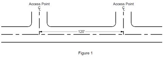
B. In situations where site distance is limited, the numbers in Table 17 shall be the minimum distance allowed between the centerlines of adjacent access points or the centerline of an access point and the near side of the nearest street. If a development improves sight distance, then Table 16 shall apply.
|
Speed on Adjacent Street |
Desirable Conditions |
Limiting Conditions |
|---|---|---|
|
25 |
150 |
100 |
|
30 |
210 |
160 |
|
35 |
300 |
240 |
Distance in feet measured center to center of access drives.
C. In situations where an access point is served by one or more turn lanes, the numbers in Table 18, plus any necessary storage space in the turn lane based on expected turning volumes, shall apply. These numbers shall be the minimum distance allowed between the centerline of any access points served by a turn lane and the adjacent access point in the upstream direction; or the centerline of an access point and the near side of the nearest street in the upstream direction. In the downstream direction, Table 16 or 17 will apply. Figure 2 shows an example of access spacing with a turn lane.
|
Speed on Adjacent Street |
Desirable Conditions |
Limiting Conditions |
||||
|---|---|---|---|---|---|---|
|
Deceleration |
Storage |
Total |
Deceleration |
Storage |
Total |
|
|
25 |
85 |
100 |
185 |
75 |
50 |
125 |
|
30 |
185 |
100 |
285 |
160 |
50 |
210 |
|
35 |
280 |
125 |
405 |
240 |
75 |
315 |
Source: Tables 16, 17 and 18 were adapted from ITE, Transportation and Land Development.
Distance in feet measured center to center of access drives. Total distance includes deceleration distance plus distance needed to maneuver into the turn lane. It may be necessary to add vehicle storage space to the deceleration distance.
Figure 2: Example of access spacing for access point served by turn lane. Desirable condition at street speed of 25 mph.
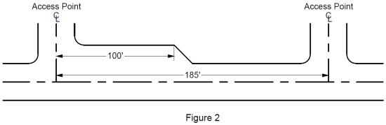
4I.050 Alignment of Offset of Cross-Street Access Points
A. If the Traffic Impact Analysis determines that there is or will be a need to signalize proposed access points, then proposed access points shall be aligned directly opposite any existing or proposed access points or T-intersection across the street.
B. Where driveways are to be signalized, a minimum spacing of 1,320 feet to any other signalized intersection should be maintained.
C. Driveways should be placed directly opposite from each other whenever possible. If this is not possible, it is necessary to provide adequate left-turn storage capacity in advance of each driveway and avoid the overlap of vehicles waiting to turn left into the driveways. If separation cannot be achieved, consideration should be given to combining the driveways. As shown in Figure 3, left-turn storage distance can be calculated using opposite and left-turn traffic volumes.
D. The requirements of A, B, and C above shall not apply if the street to be accessed has a permanent median and/or traffic control device that prevents any cross-street movement of traffic or if the Public Works Director determines that adhering to said requirements would create a hazardous or undesirable situation.
Figure 3: Nomograph for left-turn storage at an unsignalized intersection.
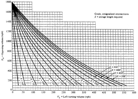
The nomograph is used by reading horizontally from the opposing traffic volume, Vo on the vertical axis and reading vertically from the left-turn volume, VL, on the horizontal axis and locating the minimum storage length, S, at the point where the horizontal and vertical lines cross. For example, 100 left-turning vehicles per hour, VL, with an opposing through volume, Vo, of 950 vph, will require a minimum storage length of about 150 feet. Source: M.D. Hamelink.
Note: Deceleration distance must be added to storage length to obtain the total length of turn bay.
4I.060 Corner Clearance from Intersections
Tables 19 and 20 can be used to determine minimum corner clearance for roadways operating at various speeds under signalized or unsignalized traffic control. Select the letter corresponding to the roadway and driveway configuration. Then locate the clearance value associated with that letter for the appropriate class of roadway at its prevailing operating speed. The guidelines provided below offer additional standards in establishing corner clearances. These include:
A. In cases where corner clearances are not attainable because property frontages are narrow, access should be located as close as practicable to the property line most distant from the intersection. At such locations, serious consideration should be given to physically prohibiting left turns into and out of the driveway.
B. Driveway locations near controlled intersections must not interfere with traffic operations that develop from the 90th percentile queue length. This situation must be checked for Item C and H in Tables 19 and 20. Conduct independent intersection queue analysis for determination. In situations where this is unavoidable, the City Engineer may limit the access point to a right-turn only in-and-out operation.
|
Item |
Street Operating Speed |
||
|---|---|---|---|
|
|
25 |
30 |
35 |
|
A |
150 |
230 |
275 |
|
B |
75 |
115 |
135 |
|
C1 |
150 |
230 |
275 |
|
D |
150 |
230 |
275 |
|
E |
95 or 0 |
115 or 0 |
135 or 0 |
1 Listed distances are minimum, refer to 4I.060 (B)
Figure 4
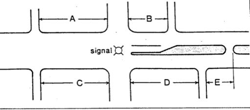
|
Item |
Street Operating Speed |
||
|---|---|---|---|
|
|
25 |
30 |
35 |
|
F |
95 |
115 |
135 |
|
G |
75 |
85 |
105 |
|
H1 |
95 |
115 |
135 |
|
J |
95 |
115 |
135 |
|
K |
95 or 0 |
115 or 0 |
135 or 0 |
1 Listed distances are minimums, refer to 4I.060 (B)
Figure 5
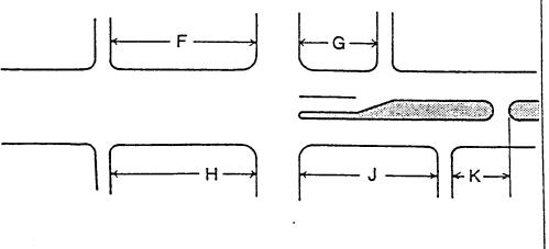
4I.070 Number of Access Points
No development shall have more than one access point unless the Traffic Impact Analysis or Emergency Service requirements determine that additional access points are needed to serve the expected volume of traffic; to establish efficient movement of vehicles, including trucks, buses, or emergency vehicles; to reduce traffic conflicts; and provided that adequate space exists.
4I.080 Access Location Based on Street Class
When a development will be situated so that there is a choice of possible access points onto streets of different classes as defined in the Street Design Standards, Table 2, then access shall be allowed only on the street of lower class, unless the Traffic Impact Analysis determines that the street of lower class cannot provide adequate access capacity, sight distance, separation or roadway intersections, safety, or vehicle maneuver area. However, an industrial or commercial development should not have as its primary access a Neighborhood Collector street, Local Access street, or residential alley, as defined in the Street Design Standards, Table 2. Traffic calming device(s) shall be provided at all access points to an industrial or commercial development from a Neighborhood Collector, Local Access Street or residential alley.
Access to corner lots shall be located on the minor street whenever possible and as close as possible to the property line most distant from the intersection.
4I.090 Combined or Shared Access
Any development expected to generate no more than 50 peak-hour trips, according to trip generation data from ITE or other reliable source, may be required to share access with an adjacent site or sites in order to reduce the total number of access points. When shared access is not feasible at the time of development but may be feasible in the future, any access point(s) shall be located at or near the edge of the property and designed to facilitate future connection to/from adjacent sites, provided such location does not conflict with other provisions of these regulations. Traffic connections between sites shall be designed and located so as not to encourage high-speed traffic, traffic conflicts with pedestrians, or through traffic.
4I.100 Direction of Driveways (One-Way or Two-Way)
Installing two, one-way driveways is warranted at point locations on all types of roadways and shall use the following criteria:
A. The level of development should be less than 60 driveways per mile.
B. Roadway ADT should be greater than 10,000, and roadway speed shall be less than 35 mph.
C. At a commercial site, at least 40 vehicles per hour are expected to turn left across through traffic to enter the driveway during peak periods.
D. Frontage widths should be at least 150 feet where practical to ensure that minimum drive separation distances can be attained.
4I.110 Adjustment for Street Gradient
If the street to be accessed has a gradient of three percent or more, distances specified in these regulations shall be adjusted to compensate for the effects of gradient on vehicle acceleration or deceleration.
4I.120 Drive-Through Windows
Drive-through windows and the approaches to them must be located and designed to accommodate on-site the maximum expected vehicle queue, with no spillover of the vehicle queue onto adjacent streets or adjacent sites and with no interference with vehicles, pedestrians, and bicyclists at points of access or egress.
4I.130 Monitoring and Enforcement
If an access point for a new development is found not to be in compliance with these regulations, the City may order, by certified letter to the developer, that any noncomplying access point(s) be made to comply within 90 days. Any such access point not made to comply within 90 days may be closed by a barricade installed by the City. Any barricade installed according to these provisions shall be moveable or otherwise situated to allow emergency access.
4I.140 Design of Access Points and Driveways
The point of intersection between streets and access drives serving developments shall be designed as much as feasible within the constraints of the given terrain and available land area to minimize interference with through traffic on the street and to minimize conflict between vehicles at the access point and between vehicles and pedestrians or bicycles. The following design features shall apply where appropriate:
A. All Access Points
1. Access point geometrics. The maximum driveway width for two-way access drives onto an arterial or collector shall be 20 feet for residential, 30 feet for commercial uses, and 35 feet for industrial uses. Maximum driveway widths for one-way access drives onto an arterial or collector shall be 20 feet for residential, 20 feet for commercial, and 25 feet for industrial uses. A wider driveway width may be approved where a substantial percentage of oversized vehicle traffic exists, where divisional islands are desired, or where multiple exit or entrance lanes are needed.
The maximum driveway width onto a local access street shall be 20 feet for residential uses and 26 feet for commercial uses.
2. Angle. The angle between the extended centerline of a driveway and the centerline of the street being accessed shall be 90 degrees, or as close to 90 degrees as feasible. In no case shall an angle of less than 60 degrees nor more than 120 degrees be allowed.
3. Visual clues of access. Signs, landscaping, and other on-site features near an access point shall be designed and located to provide clues to the location of the access point without interfering with drivers’ sight distance and without significantly reducing the ability to see vehicles on the driveway or on the street.
4. Change of existing access. A developer may be required to change and/or abandon existing curb cuts, driveway designs, and other access-related features established for a previous development or land use.
5. Design vehicles. For commercial developments where access by trucks with trailer is not expected to be routine, the geometric design of access points shall be based primarily on the turning characteristics of passenger cars (defined by the AASHTO “P” design vehicle).
For industrial developments or any other development where access by trucks with trailers is expected to be routine, the geometric design of access points to be used by trucks shall be based on the turning characteristics of the AASHTO “WB-50” design vehicle.
Developments where on-site bus access is expected shall be designed to accommodate bus movement as defined by the AASHTO “BUS” design vehicle.
6. Pedestrian and bicycle movement. As much as is feasible within the parameters of these regulations, access points and driveways shall be designed to minimize conflict between vehicles and pedestrians or bicycles. Access points and driveways shall be designed to minimize the total risk and delay for vehicles, pedestrians using sidewalks or crosswalks, and bicycle riders using bike paths, streets, or driveways.
7. All driveways will be designed so that vehicles entering and exiting are able to turn without encroaching on adjacent lanes, either on the roadway or in the driveway.
8. Driveways must be noticeable to all drivers. This can be accomplished through the use of contrasting pavement, driveway and curb or curb and gutter color, compared to the roadway. Contrasting pavement can help to guide and regulate drivers.
9. Grade. The access drive shall intersect the street with a continuous, smooth grade not interrupted by curb, gutter, sidewalks, or any other rough, bumpy, or off-grade feature. Sidewalks or bike paths crossing such access points shall be at grade.
10. Striping. Multi-lane driveways shall have lanes delineated by paint stripes. Lanes in the same direction shall be delineated by a skip white line 4 inches wide. Lanes in opposite direction (if not separated by a median) shall be delineated by a double solid yellow line, with each stripe 4 inches wide.
11. Markings, like signs, have the function of controlling traffic to encourage safe and expeditious operation. Markings either supplement the traffic signs or serve independently to indicate certain regulations or hazardous conditions. All pavement markings shall meet the standards set forth in the Manual on Uniform Traffic Control Devices (MUTCD) and City of Olympia Standards.
12. All traffic signs within the right-of-way shall meet the standards set forth in the MUTCD and City of Olympia Standards.
B. High Volume Access Points
For any development expected to generate at least 75 vehicle trips in the development’s peak hour, the following conditions shall apply in addition to those under Section A above.
1. Throat length. Throat length is defined as the distance along an access driveway between the back edge of the driveway apron and a development’s parking area. For high-volume access points, adequate throat length for various land uses is specified in Table 21. A development with more than one access point or with multi-lane access driveways may be allowed shorter throat length if adequate vehicle storage can be provided on each access driveway.
In the downtown business area (designed “DB” on the City of Olympia Zoning Map) and along high-density residential corridors, the City Engineer may allow a shorter throat length or may change other guidelines in keeping with that area’s high density and pedestrian/transit orientation.
|
Land Use |
Size |
Min. Throat Length (ft.) |
Min. Total Storage (ft.) |
|---|---|---|---|
|
Light Industrial |
<100,000 ft2 |
50 |
100 |
|
100,000 - 500,000 ft2 |
100 |
600 |
|
|
>500,000 ft2 |
200 |
1,000 |
|
|
Discount Store |
30,000 ft2 or less |
50 |
300 |
|
30,000 ft2 |
75 |
600 |
|
|
Shopping Center |
<250,000 ft2 |
50 |
500 |
|
250,000 - 500,000 ft2 |
75 |
1,000 |
|
|
500,001 - 750,000 ft2 |
200 |
1,500 |
|
|
750,000 ft2 |
250 |
2,000 |
|
|
Supermarket |
20,000 ft2 or less |
75 |
300 |
|
>20,000 ft2 |
125 |
500 |
|
|
Apartment |
<100 units |
50 |
300 |
|
100-200 units |
75 |
500 |
|
|
>200 units |
125 |
750 |
|
|
Quality Restaurant |
15,000 ft2 or less |
50 |
100 |
|
>15,000 ft2 |
75 |
150 |
|
|
Drive-in Restaurant |
2,000 ft2 or less |
75 |
100 |
|
>2,000 ft2 |
100 |
200 |
|
|
General Office |
<50,000 ft2 or less |
50 |
500 |
|
50,000 - 100,000 ft2 |
75 |
750 |
|
|
100,001 - 200,000 ft2 |
100 |
1,000 |
|
|
200,001- 500,000 ft2 |
150 |
1,500 |
|
|
>500,000 ft2 |
250 |
2,000 |
|
|
Motel |
105 rooms or less |
75 |
150 |
|
>150 rooms |
100 |
200 |
Source: Adapted from ITE, Transportation and Land Development.
2. Curb return. All high-volume access points must provide curb return radii from private driveways to public streets as described in Table 22. By a Traffic Impact Analysis, a lower standard design may be allowed provided that the expected traffic volume can be adequately and safely accommodated. If significant truck traffic is expected, wider lanes and greater curb return radii may be required.
|
Land Use |
Desirable (ft.) |
Maximum (ft.) |
Minimum (ft.) |
|---|---|---|---|
|
Apartment/Commercial |
20 |
25 |
15 |
|
Industrial |
30 |
30 |
20 |
Source: Adapted from ITE, Transportation and Land Development.
3. Signalization. High-volume access points may be signalized if the Traffic Impact Analysis determines that signalization is warranted. Any signal so installed shall be coordinated with other nearby signals.
4. Street median opening. The most important design element for the raised divider is the median width that must be adequate to completely shadow left-turning vehicles from through vehicles. Median width shall be as specified in the standard street cross section designated by functional class. For conditions that do not apply to the standard street cross section, refer to Table 23.
Where a median and/or pedestrian crossing island is desirable or required in a two-way center turn lane, refer to Standard Drawing 4-48.
Median openings should be designed to accommodate the design vehicle turning at a reasonable rate of speed. Semicircular radii may be used on the noses of medians up to 6 feet wide. Bull-nosed medians should be used for medians of greater width, using a minimum inside turning radius of 40 feet and a minimum nose-to-nose dimension of 40 feet for passenger vehicle design. To accommodate SU vehicles, a 50-foot control radius is recommended, and for WB-40 vehicles, a 75-foot radius.
|
Function |
Minimum Width (ft.) |
Desired Width (ft.) |
|---|---|---|
|
Separation of Opposing Traffic |
41 |
10 |
|
Pedestrian Refuge and Space for Traffic Control |
61 |
14 |
|
Left-turn Speed Change and Storage |
14 |
20 |
|
Crossing/Entering Vehicle Protection |
20 |
40 |
|
U-turns, Inside-to-inside Lane |
26 |
60 |
1 Cannot accommodate left-turn lanes, hence such turns must be made from the through lanes unless prohibited by signs.
2 Use in situations not covered by standard street cross sections.
Source: ITE, Guidelines for Urban Major Street Design.
Providing openings within a raised median barrier allows selected driveways full or partial left-turn access into or out of the driveway. Benefits gained from providing median openings can include:
a. Limits left-turn access into or out of a driveway to a specific location, thereby reducing vehicle conflict points.
b. Improves the operation of both the driveway and the roadway by the reduction of vehicle points.
c. Provides an access point that may prevent a more circuitous route required to enter or leave driveways that could cause added traffic on local parallel streets. Table 24 shows the recommended spacing for barrier openings.
|
Speed on Adjacent Street |
Desirable Conditions |
Limiting Conditions |
|---|---|---|
|
25 |
300 |
140 |
|
30 |
370 |
190 |
|
35 |
460 |
240 |
All speeds, openings provided at all arterials, collectors, and some local streets.
* Plus 25 feet for each car stored in turn lane at expected maximum queue length.
Source: Adapted from ITE, Transportation and Land Development.
C. Low-Volume Access Points
For any development expected to generate less than 75 vehicle trips in the development’s peak hour, the following conditions shall apply in addition to those under Section A above.
1. Driveways will be constructed to the City of Olympia Engineering Design and Development Standards, Standard Drawing 4-7A, 4-7B, 4-7C, or 4-7D, Cement Concrete Driveway.
2. Left-turn lane warrants. Left turns shall be prohibited to and/or from driveways under the following conditions:
a. Inadequate corner clearance (prohibit left turns to and from).
b. Inadequate sight distance (prohibit left turns with inadequate sight distance).
c. Inadequate driveway spacing (prohibit left turns to and from).
In addition, where volume warrants it, left-turning vehicles should be given a left-turn bay.
Figure 6 provides a method for determining the warrant that must be met in order to add left-turn lanes. A left-turn lane is determined to be warranted when a set percent of left turns are expected based on a relationship of the opposing volume to the advancing volume per lane. Drawing lines vertically from the advancing volume axis and horizontally from the opposing volume axis allows a determination of the warrant where the lines intersect. If the actual left-turn volume, measured in percentage of the advancing intersection of the vertical and horizontal lines, then a left turn is likely warranted. For example, if the advancing volume is 500 vehicles per hour (vph) and the opposing is 250 vehicles per hour, the lines intersect between the 5 percent and 10 percent curves at approximately 8 on the figure. Therefore, if the left-turn volume equals 8 percent or more of the advancing volume, 40 vph or more, then the left-turn is likely warranted. Left turns must be a minimum of 5 percent of approach volume in order to use this figure. As the advancing and opposing volumes increase, the percentage of left turns required decreases. This is because as the advancing volume increases, the need to remove left-turn vehicles from the advancing volume increases and as the opposing volume increases, the harder it becomes for the left-turning traffic to cross the opposing traffic.
Channelization will also depend upon other standards such as site circulation, traffic volumes, accident history, and parking layouts.
Figure 6: Left Turn Warrant
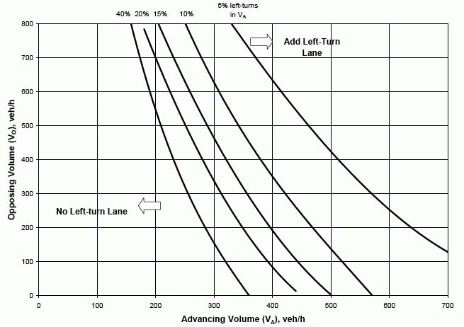
Appendix 1: List of Drawings
|
Title |
Drawing No. |
File Type |
|---|---|---|
|
|
Chapter 4 – All |
|
|
Minimum Clear Site Triangle |
4-1A |
|
|
Clear Site Triangle for Uncontrolled Intersections |
4-1B |
|
|
Clear Site Triangle for Stop or Yield Controlled Intersections |
4-1C |
|
|
Arterial Boulevard |
4-2A |
|
|
Arterial Boulevard with LID Swale |
4-2A-LID |
|
|
Arterial |
4-2B |
|
|
Arterial with LID Swale |
4-2B-LID |
|
|
Major Industrial Collector |
4-2C |
|
|
Major Industrial Collector with LID Swale |
4-2C-LID |
|
|
Commercial Collector Boulevard |
4-2D |
|
|
Commercial Collector |
4-2E |
|
|
Commercial Collector with LID Swale (sheet 1 of 2) |
4-2E-LID1 |
|
|
Commercial Collector with LID Swale (sheet 2 of 2) |
4-2E-LID2 |
|
|
Major Collector Boulevard |
4-2F |
|
|
Major Collector Boulevard with LID Swale |
4-2F-LID |
|
|
Major Collector |
4-2G |
|
|
Major Collector with LID Swale |
4-2G-LID |
|
|
West Bay Drive Major Collector Series: |
4-2G1 through 4-2G7 |
|
|
Harrison Avenue to Park Property South Border |
4-2G1 |
|
|
Harrison Avenue to Park Property South Border-Notes |
4-2G1A |
|
|
Park Property South Border to Garfield Trail |
4-2G2 |
|
|
Park Property South Border to Garfield Trail-Notes |
4-2G2A |
|
|
Garfield Trail to Brawne Avenue Intersection |
4-2G3 |
|
|
Garfield Trail to Brawne Avenue Intersection-Notes |
4-2G3A |
|
|
Brawne Avenue Intersection to Park Property North Border |
4-2G4 |
|
|
Brawne Avenue Intersection to Park Property North Border-Notes |
4-2G4A |
|
|
Park Property North Border to Base of Schneider Hill |
4-2G5 |
|
|
Park Property North Border to Base of Schneider Hill-Notes |
4-2G5A/B |
|
|
Schneider Hill |
4-2G6 |
|
|
Schneider Hill-Notes |
4-2G6A |
|
|
Schneider Hill to Marina-Model |
4-2G7 |
|
|
Schneider Hill to Marina-Notes |
4-2G7A |
|
|
Boulevard Road |
4-2G8 |
|
|
Legion Way Commercial Collector Plum Street to Cherry Street |
4-2G10 |
|
|
Neighborhood Collector Boulevard |
4-2H |
|
|
Neighborhood Collector Boulevard with LID Swale |
4-2H-LID |
|
|
Neighborhood Collector Street |
4-2I |
|
|
4-2I-LID |
||
|
Local Access Street |
4-2J |
|
|
4-2J1 |
||
|
Local Access Street with Full Dispersion |
4-2JX2 |
|
|
Local Access Street Block Spacing <350 Ft. |
4-2K |
|
|
4-2K-LID |
||
|
Trails/Shared Use Path |
4-2L |
|
|
4-3 |
||
|
Roadway Pavement for Residential Alleys-Plan View |
4-4A |
|
|
Roadway Pavement for Residential Alleys-Section Views |
4-4B |
|
|
Cul-de-sac or Temporary Intersection “T” |
4-5 |
|
|
Pavement Design |
4-6A |
|
|
Pavement Design Worksheet |
4-6B |
|
|
Cement Concrete Driveway Entrance Type 1 |
4-7A |
|
|
Cement Concrete Driveway Entrance Type 2 |
4-7B |
|
|
Cement Concrete Driveway Entrance Type 3 |
4-7C |
|
|
Cement Concrete Driveway Entrance Type 4 |
4-7D |
|
|
Cement Concrete Driveway Entrance Pay Limits |
4-7E |
|
|
Driveway Approach with Culvert |
4-7F |
|
|
Trench-Pavement Restoration Detail |
4-8 |
|
|
Pavement Replacement |
4-8A |
|
|
Concrete Pavement Replacement |
4-8B |
|
|
Asphalt Pavement Restoration |
4-8C |
|
|
Pervious Concrete Sidewalk |
4-9A |
|
|
Pervious Concrete Underdrain System |
4-9B |
|
|
Impermeable Concrete Sidewalk |
4-9C |
|
|
Cement Concrete Integral Curb and Walk Type “A” |
4-9D |
|
|
Cement Concrete Integral Curb and Walk Driveway |
4-9E |
|
|
Sidewalk Spacing Expansion Joints & Score Marks |
4-10 |
|
|
Perpendicular Curb Ramp Type “A” |
4-12A |
|
|
Perpendicular Curb Ramp Type B (Shown with Buffer) |
4-12B |
|
|
Perpendicular Curb Ramp Type C |
4-12C |
|
|
Parallel Curb Ramp Type A |
4-12D |
|
|
Parallel Curb Ramp Type B |
4-12E |
|
|
Combination Curb Ramp (Sheet 1 of 2) |
4-12F1 |
|
|
Combination Curb Ramp (Sheet 2 of 2) |
4-12F2 |
|
|
Single Direction Curb Ramp (Sheet 1 of 2) |
4-12G1 |
|
|
Single Direction Curb Ramp (Sheet 2 of 2) |
4-12G2 |
|
|
Curb Ramp Pay Limits |
4-12H |
|
|
Intersection Radii |
4-13 |
|
|
Curb Bulb-Out Adjacent to Vehicle Lane |
4-13A |
|
|
Curb Bulb-Out Adjacent to Bike Lane |
4-13A1 |
|
|
Local Access Street Parking Bulb-out |
4-13B |
|
|
One-Lane Narrow Point |
4-13C |
|
|
Two-way Angle Slow Point, Sheet 1 of 2 |
4-13C1 |
|
|
Two-Way Angle Slow Point, Sheet 2 of 2 |
4-13C2 |
|
|
Mountable Concrete Traffic Island for Two-way Angle Slow Point |
4-13D |
|
|
Cement Concrete Traffic Curb |
4-14 |
|
|
Cement Concrete Curb and Gutter |
4-14A |
|
|
Type “W” HMA Wedge Curb |
4-14B |
|
|
Cement Concrete Wedge Curb and Gutter |
4-14C |
|
|
Replacement of Existing Curb and/or Sidewalk Typical Pavement Patching |
4-14D |
|
|
Bikeway Classes |
4-16 |
|
|
Mailbox Cluster |
4-18 |
|
|
Service Disconnect for Streetlights and Traffic Signals |
4-19 |
|
|
Poured in Place Monument |
4-20 |
|
|
Case Monument |
4-23A |
|
|
Rock Retaining Wall Drainage |
4-26 |
|
|
Landscape Timbers |
4-26A |
|
|
Striping Detail |
4-27A |
|
|
Striping Detail |
4-27B |
|
|
Striping Detail |
4-27C |
|
|
Bicycle Detector Symbols |
4-27D |
|
|
Striping Detail Marking Patterns |
4-27F |
|
|
Typical Street Light Layouts |
4-30 |
|
|
Typical Street Light Installation |
4-31 |
|
|
Street Light Installation Details Combined |
4-31A |
|
|
Crosswalk and Curb Ramp Locations/Stop Bar Dimensions for Retrofit Situations |
4-32 |
|
|
Bar-type Crosswalk Detail |
4-32A |
|
|
Streetlight Standard Foundation |
4-33 |
|
|
Luminaire-Foundation for Pedestrian Scale Poles |
4-33A |
|
|
Signal or Strain Pole Foundation |
4-34 |
|
|
Type “D” Loop for Bicycle Lanes |
4-35 |
|
|
Beacon/Gong Assembly for Emergency Vehicle Preemption Indication |
4-36 |
|
|
Mast Arm Street Sign Construction |
4-37 |
|
|
Street Name Sign |
4-37B |
|
|
Chip Seal Rumble Strip Making Detail |
4-38 |
|
|
Right-in, Right Out Detail |
4-39 |
|
|
Traffic Circle |
4-40A |
|
|
Traffic Circle Intersection Diagram |
4-40B |
|
|
Traffic Circle Dimension Chart |
4-40C |
|
|
Traffic Circle Sign Detail |
4-40D |
|
|
Traffic Circle Sign Detail |
4-40E |
|
|
Traffic Circle Sign Detail |
4-40F |
|
|
Traffic Circle Sign Detail |
4-40G |
|
|
Traffic Circle Sign Detail |
4-40H |
|
|
Typical Parking Meter Post Installation |
4-41A |
|
|
Typical Parking Meter Post Placement and Parking Stall Layout |
4-41B |
|
|
Speed Cushion |
4-42A |
|
|
22-Foot Speed Bump |
4-42B |
|
|
14-Foot Speed Bump |
4-42C |
|
|
Speed Bump/Cushion Details |
4-42D |
|
|
Typical Pedestal for Controller Cabinet and Service |
4-43 |
|
|
Standard Utilities Locations Schematic |
4-44 |
|
|
Typical Sign Installation Detail |
4-45 |
|
|
Private Access Lane |
4-46 |
|
|
Fire Lane Sign |
4-47 |
|
|
Pedestrian Refuge Landscaped Island Details |
4-48 |
|
|
Pedestrian Refuge Concrete Island Details |
4-48A |
|
|
Street Tree Frame and Grate Details |
4-49 |
|
|
Tree Planting in Planter Strip |
4-50 |
|
|
Tree Well with Grate Planting Detail (Poor Soil Quality) |
4-51 |
|
|
Tree Well with Grate Planting Detail (Adequate Soil) |
4-52 |
Appendix 2: Index of Tables
|
Table |
Page No. |
|---|---|
|
Table 1: Street Classification and Number of Lanes |
6 |
|
Table 2: Street Design Standards |
10 |
|
Table 3: Street Characteristics |
11 |
|
Table 4: West Bay Drive Street Streetside Improvements |
15 |
|
Table 5: Boulevard Road Street Frontage Improvements |
16 |
|
Table 6: East Downtown Streetside Improvements |
17 |
|
Table 7: Centerline Offsets |
19 |
|
Table 8: Intersection Sight Distance |
21 |
|
Table 9: Uncontrolled Intersection Sight Distance |
22 |
|
Table 10: Pavement Restoration Requirements |
26 |
|
Table 11: Surface Temperature Limitations |
27 |
|
Table 12: Testing and Sampling Frequency Requirements |
32 |
|
Table 13: Trail and Shared-Use Path Design Standards |
41 |
|
Table 14: Illumination Standards |
43 |
|
Table 15: Average Maintained Horizontal Illumination (Foot-candles) |
47 |
|
Table 16: Minimum Access Spacing Based on Separation of Conflict Area |
65 |
|
Table 17: Minimum Access Spacing Where Sight Distance is Limited |
65 |
|
Table 18: Minimum Access Spacing for Access Points Served by Turn Lanes |
66 |
|
Table 19: Signalized Intersection Control - Minimum Corner Clearances for Urban Conditions |
68 |
|
Table 20: Stop Sign Intersection Control - Minimum Corner Clearances for Urban Conditions |
69 |
|
Table 21: Minimum Throat Length and On-site Vehicle Storage |
74 |
|
Table 22: Curb Return Radius for High Volume Access Drives |
74 |
|
Table 23: Recommended Median Widths |
75 |
|
Table 24: Minimum Spacing Between Median Openings |
76 |
Appendix 3: Monument Preservation Documentation Letter
|
I, __________________, representing __________________, pursuant to |
|||||||||||||||||||
|
|
(Licensed Surveyor) |
|
|
|
|
|
|
(Contractor) |
|
|
|
|
|
||||||
|
WAC Chapter 332-120 Survey Monuments-Removal or Destruction, certify that I have reviewed the construction plans for __________________ and complied |
|||||||||||||||||||
|
|
|
|
|
|
|
|
|
|
|
|
|
(Project) |
|
|
|
|
|
|
|
|
with the following: |
|||||||||||||||||||
|
1. Defined the areas where the proposed construction may disturb or destroy survey monuments. |
|||||||||||||||||||
|
2. Made a diligent search of survey records in Thurston County to determine possible locations and type of existing monuments. |
|||||||||||||||||||
|
3. Made a diligent field search within the defined construction limits at locations determined from the survey records research. |
|||||||||||||||||||
|
4. Made an additional diligent field search for unrecorded monuments at locations not defined from survey records but in locations where survey monuments typically exist. |
|||||||||||||||||||
|
5. Supplied City of Olympia with a map outlining the project boundary search area with the individual search areas being further defined indicating the type of monument found or that the monument was searched for and not found. (Map attached) |
|||||||||||||||||||
|
6. Each found monument has been referenced to at least 3 nearby points not likely to be destroyed with this construction. (Copies of references attached) |
|||||||||||||||||||
|
7. Permits have been obtained from the Department of Natural Resources according to WAC Chapter 332-120. (Copies of permits attached) |
|||||||||||||||||||
|
This certification is for the expressed purpose of preserving the existing location and type of survey monuments within the construction area. It is not for the purpose of verifying that these monuments mark the location of previously surveyed positions. I will submit a Monument Completion Report, and submit a copy of the Report to the City Surveyor or City Engineer. |
|||||||||||||||||||
|
Signed and Sealed, |
|||||||||||||||||||
Appendix 4: Downtown Boundaries
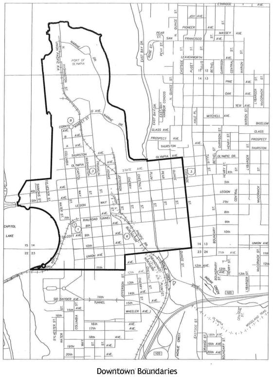
Appendix 5 TRANSPORTATION-RELATED SPECIAL PROVISIONS
SECTION 1-10, TEMPORARY TRAFFIC CONTROL
SECTION 5-02, BITUMINOUS SURFACE TREATMENT
SECTION 5-04, HOT MIX ASPHALT
SECTION 8-20, ILLUMINATION, TRAFFIC SIGNAL SYSTEMS, INTELLIGENT TRANSPORTATION SYSTEMS, AND ELECTRICAL
SECTION 8-21, PERMANENT SIGNING
SECTION 8-22, PAVEMENT MARKING
SECTION 8-27, VACANT
SECTION 9-28, SIGNING MATERIALS AND FABRICATION
SECTION 9-29, ILLUMINATION, SIGNAL, ELECTRICAL
INTRODUCTION
This Appendix 5 of Chapter 4 of the EDDS supplements, modifies or replaces applicable sections of the Standard Specifications for Road, Bridge and Municipal Construction, 2021 edition, as issued by the Washington State Department of Transportation (WSDOT) (hereafter “Standard Specifications”). The Standard Specifications, as modified or supplemented by this appendix, are part of the EDDS and shall govern all associated work.
The deletion, amendment, alteration, or addition to any subsection or portion of the Standard Specifications is meant to pertain only to that particular portion of the section, and in no way should it be interpreted that the balance of the section does not apply.
SECTION 1-10, TEMPORARY TRAFFIC CONTROL
1-10.2(2) Traffic Control Plans
(January 1, 2015 – OLY GSP)
Supplement this section with the following:
If the Contractor intends to propose de-energizing or otherwise altering the function of the signals at a signalized intersection within or adjacent to the work zone, the Contractor must submit for approval a Contractor-developed plan to do so at least 15 working days before such alteration is proposed to begin. Such a temporary signal alteration plan shall include a written justification for altering the function of the signals, including any safety concerns related to pedestrian and vehicular (including emergency vehicles) traffic within the work zone.
SECTION 5-02, BITUMINOUS SURFACE TREATMENT
5-02.3(11) Temporary Raised Pavement Markings
(August 4, 2014 - WSDOT AMENDMENT)
Revise this section title to read:
5-02.3(11) Temporary Pavement Markings
(August 4, 2014 - WSDOT AMENDMENT)
The word "raised" is deleted from this section.
SECTION 5-04, HOT MIX ASPHALT
5-04.3(2) Paving Under Traffic
(January 1, 2021 - OLY GSP)
Supplement this section with the following:
The Contractor shall keep intersections open to traffic at all times, except when paving operations through an intersection requires closure. Such closure shall be kept to the minimum time required to place, compact, and cool the HMA mixture as appropriate. Each individual intersection closure or partial closure shall be addressed in the Paving Coordination Plan including closure requirements for adjacent and intersecting streets.
5-04.3(4) Preparation of Existing Paved Surfaces
(March 7, 2018 - OLY GSP)
Supplement this section with the following:
All surface iron including, but not limited to, manhole rings and covers, valve box covers, catch basin frame and grates, and monument case and covers shall be lowered prior to pavement planing and pulverization. The only exception to this will apply to catch basins where the frame and grates are integral to the curb and lowering them would require removal and replacement of curb and gutter. Prior to lowering the iron, the Contractor shall establish three (3) reference points per surface iron.
All vegetation including root structures and moss shall be removed in their entirety within the paved areas including adjoining curbs, gutters, and sidewalks. Further, any vegetation overgrowth, that in the opinion of the Engineer would impair paving operations, shall be trimmed and removed six inches from proposed HMA edge limits.
Driveway preparation shall include saw cutting, filling, and grading the transitional area required to provide a HMA approach between the edge of pavement and driveway regardless of the existing surface treatment or width. Where a driveway or sidewalk interferes with the new roadway surface, the Engineer shall mark in the field where the asphalt or concrete shall be sawcut. All material that must be removed from the driveway shall be hauled and properly disposed of off the project site.
All imported material required to match grade for driveway bases shall be paid for by the unit bid item “Crushed Surfacing Top Course.” All adjacent driveways shall require some preparation. Temporary access shall be provided for all driveways prior to paving. There shall be no additional compensation for those driveways requiring more preparation than others.
5-04.3(5)A Preparation of Existing Surfaces
(January 1, 2015 - OLY GSP)
Supplement this section with the following:
All surface iron including, but not limited to, manhole rings and covers, valve box covers, catch basin frame and grates, and monument case and covers shall be lowered prior to pavement planing and pulverization. The only exception to this will apply to catch basins where the frame and grates are integral to the curb and lowering them would require removal and replacement of curb and gutter. Prior to lowering the iron, the Contractor shall establish three (3) reference points per surface iron.
All vegetation including root structures and moss shall be removed in their entirety within the paved areas including adjoining curbs, gutters, and sidewalks. Further, any vegetation overgrowth, that in the opinion of the Engineer would impair paving operations, shall be trimmed and removed six inches from proposed HMA edge limits.
Driveway preparation shall include saw cutting, filling, and grading the transitional area required to provide a HMA approach between the edge of pavement and driveway regardless of the existing surface treatment or width. Where a driveway or sidewalk interferes with the new roadway surface, the Engineer shall mark in the field where the asphalt or concrete shall be sawcut. All material that must be removed from the driveway shall be hauled and properly disposed of off the project site.
All imported material required to match grade for driveway bases shall be paid for by the unit bid item “Crushed Surfacing Top Course.” All adjacent driveways shall require some preparation. Temporary access shall be provided for all driveways prior to paving. There shall be no additional compensation for those driveways requiring more preparation than others.
5-04.3(7) Spreading and Finishing
(January 1, 2021 - OLY GSP)
Supplement this section with the following:
The Contractor shall complete the first lift of HMA over the entire length of the project, before the final lift will be allowed to be installed. If traffic signal loops are required, all loops shall be installed prior to the final lift.
5-04.3(12) Joints
(January 1, 2010 - OLY GSP)
Supplement this section with the following:
Cold joints shall be allowed only at locations approved by the Engineer. Upon completion of paving operations, all cold joints including longitudinal joints shall be sealed with PG 64-22 asphalt binder.
5-04.3(17) Paving Under Traffic
(February 5, 2014 - OLY GSP)
Supplement this section with the following:
The Contractor shall keep intersections open to traffic at all times, except when paving operations through an intersection requires closure. Such closure shall be kept to the minimum time required to place, compact, and cool the HMA mixture as appropriate. Each individual intersection closure or partial closure shall be addressed in the Paving Coordination Plan including closure requirements for adjacent and intersecting streets.
Add the following new sub-section:
5-04.3(22) Trench Restoration
(January 1, 2012 - OLY GSP)
All excavations within or across streets, driveways, or failure of existing pavement that will be exposed to traffic shall be temporarily patched by the end of the working day or as directed by the Engineer. The patch shall be constructed of a two (2) inch lift of Commercial HMA. The Contractor shall maintain all temporary patches until such time as the permanent pavement is in place. Temporary patching shall be free of potholes, bumps, and be free draining. Any portion of the trench that is not patched by the end of the work day shall be covered with steel plates. Steel plates will be secured in-place and have a wedge of cold mix or other suitable material, as determined by the Engineer, placed along the steel plate edges to provide a smooth transition for vehicle traffic. All costs associated with the supply, haul, placement and removal of the steel plating, including cold mix, shall be included in the cost of installation of the respective utility pipe and no other compensation shall be allowed.
SECTION 8-20, ILLUMINATION, TRAFFIC SIGNAL SYSTEMS, INTELLIGENT TRANSPORTATION SYSTEMS, AND ELECTRICAL
8.20.1(3) Permitting and Inspection
(March 1, 2020 - OLY GSP)
Delete and replace the second and third paragraphs with the following:
The contractor shall be responsible for coordinating, applying, and paying for the City of Olympia Electrical Permit required to complete the electrical work on this project. All costs to obtain and comply with electrical permits shall be included in the applicable bid item(s) for the electrical work involved.
The City's Electrical Inspector shall inspect and approve the electrical portions of the project. The Contractor shall notify the City Electrical Inspector within 48 hours in advance of required field inspection.
8-20.2(1) Equipment List and Drawings
(January 1, 2014 - OLY GSP)
Supplement this section with the following:
Pole base to the light source (H1) for lighting standards with pre-approved plans shall be as noted in the Plans.
Pole base to light source distances (H1) for lighting standards without pre-approved plans will be furnished by the Engineer as part of the final approved shop drawings, prior to fabrication.
If traffic signal standards, strain pole standards, or combination traffic signal and lighting standards are required, final verified dimensions including pole base to signal mast arm connection point, pole base to light source distances (H1), mast arm length, offset distances to mast arm mounted appurtenances, and orientations of pole mounted appurtenances will be furnished by the Engineer as part of the final approved shop drawings, prior to fabrication.
8-20.3(5)A General
(August 5, 2013 – OLY GSP)
Delete and replace the third paragraph with the following:
All new conduit and all innerduct shall be blown clean with compressed air. Then in the presence of the Engineer, an 80 percent sizing mandrel, correctly sized for the raceway, shall be pulled through to ensure that the raceway has not been deformed. This shall be done prior to pulling wire or fiber optic cable and after final assembly is in place.
8-20.3(5)B Conduit Type
(April 1, 2013 – OLY GSP)
Delete item 2,”All pole risers…”, from paragraph two.
(April 1, 2013 – OLY GSP)
Supplement this section with the following:
Polyvinyl chloride (PVC) conduit shall be used for all traffic signal and illumination system installations.
8-20.3(5)B2 Non-Metalic Conduit
(April 1, 2013 – OLY GSP)
Revise the third paragraph to read:
Nonmetallic conduit bends, where allowed, shall conform to Article 352.24 of the Code. Eighteen-inch radius elbows shall be used for PVC conduit of 2-inch nominal diameter or less. Standard sweep elbows shall be used for PVC conduit with greater than 2-inch nominal diameter unless otherwise specified in the Plans. All conduits, in addition to whatever illumination or signal wiring the plans call for, must have a pull line for future use. This pull line must be a minimum of 200-pound tensile polypropylene and be run between the junction boxes or termination points of all conduits. All conduits shown for future use shall have a pull line for future use as described above and an approved toning wire installed per 7-08.3(2)K for locate purposes. When HDPE conduit is used for directional boring, it shall be continuous, with no joints, for the full length of the bore. The conduit run shall be extended to the associated outlets with the same schedule HDPE or PVC conduit. Entry into associated junction box outlets shall be with the same schedule PVC conduit and elbows. The same requirements apply for extension of an existing HDPE conduit crossing.
8-20.3(5)E Method of Conduit Installation
(December 2, 2013 – OLY GSP)
Revise the first sentence to read:
Conduit shall be placed under existing pavement by approved open trenching, directional boring, jacking, or drilling methods at locations approved by the Engineer.
8-20.3(6) Junction Boxes, Cable Vaults, and Pull Boxes
(January 1, 2010 - OLY GSP)
Supplement this section with the following:
Junction boxes are shown on the plans for readability. Final locations shall be made in the field as approved by the Engineer. Junction boxes containing both street lighting and traffic signal wiring shall be marked T.S. clearly on the lid. Junction boxes for street lighting shall be marked S.L. clearly on the lid.
The Standard Plan conduit inch diameter capacity for Type 1 junction box is increased to 10 and for Type 2 junction box is increased to 16.
Type 2 junction boxes shall be provided with 12" deep extension boxes.
Type 3 or larger junction boxes shall meet the specifications outlined in WSDOT Standards Plans.
Add the following new sub-section:
8-20.3(6)A Adjusting Junction Box
(January 1, 2015 - OLY GSP)
Existing junction box locations may be required to be adjusted up to one-foot horizontally and/or vertically. The distance between the top conduit and the new junction box lid shall be maximized but not exceed 12 inches. Existing conduits coming into and/or leaving the junction box shall be exposed and adjusted as required to fit into the new junction box location. Hand digging shall be required during these adjustments.
Contractor shall supply and install a new WSDOT locking standard junction box in place of the existing junction box as part of adjusting junction box work.
8-20.3(8) Wiring
(January 1, 2015 - OLY GSP)
Delete and replace the third sentence in the fourth paragraph with the following:
Splices for induction loop circuits and magnetometer circuits shall be epoxy filled clear rigid mold kits only.
(January 1, 2010 - OLY GSP)
Delete and replace the fourth paragraph and the table following it with the following:
All termination for traffic signal control systems shall follow the conductor sequence color code as shown in the following table.
|
Conductor Number |
Color Code |
Color/Trace |
Use |
|---|---|---|---|
|
1 |
R |
Red |
Vehicle Red or Pedestrian Don't Walk |
|
2 |
O |
Orange |
Vehicle Yellow or Pedestrian Push-Button Input |
|
3 |
G |
Green |
Vehicle Green or Pedestrian Walk |
|
4 |
B |
Black |
Vehicle Spare or Pedestrian Push-Button Return |
|
5 |
W |
White |
Vehicle or Pedestrian AC Neutral |
|
6 |
WB |
White/Black |
Neutral or Spare |
|
7 |
Bl |
Blue |
Ped Call or Spare |
|
8 |
Rb |
Red/Black |
Red or Don't Walk |
|
9 |
Ob |
Orange/Black |
Yellow or Spare |
|
10 |
Gb |
Green/Black |
Green or Walk |
(January 1, 2015 - OLY GSP)
Delete and replace the seventh paragraph with the following:
Aerial illumination splices shall employ vice or crimp type pressure connectors. Splice insulation shall be epoxy type only.
Add the following new sub-section:
8-20.3(8)A Illumination System Wiring
(January 1, 2010 - OLY GSP)
An approved conductor support is required at the fixture end of the luminaire arm.
Additional conductor length shall be left inside the pole equal to a loop having a diameter of one foot.
Add the following new sub-section:
8-20.3(8)B Field Wiring Chart
(January 1, 2014 - OLY GSP)
|
Field Wiring Chart |
|---|
|
501 AC+ Input 516-520 Railroad Pre-empt |
|
502 AC- Input 5A1-5D5 Emergency Pre-empt |
|
503-510 Control-Display 541-580 Coordination |
|
511-515 Sign Lights 581-599 Spare |
|
Movement Number |
1 |
2 |
3 |
4 |
5 |
6 |
7 |
8 |
9 |
|---|---|---|---|---|---|---|---|---|---|
|
Vehicle Head |
|
|
|
|
|
|
|
|
|
|
Red |
611 |
621 |
631 |
641 |
651 |
661 |
671 |
681 |
691 |
|
Yellow |
612 |
622 |
632 |
642 |
652 |
662 |
672 |
682 |
692 |
|
Green |
613 |
623 |
633 |
643 |
653 |
663 |
673 |
683 |
693 |
|
Spare |
614 |
624 |
634 |
644 |
654 |
664 |
674 |
684 |
694 |
|
Spare |
615 |
625 |
635 |
645 |
655 |
665 |
675 |
685 |
695 |
|
AC- |
616 |
626 |
636 |
646 |
656 |
666 |
676 |
686 |
696 |
|
Red Auxiliary |
617 |
627 |
637 |
647 |
657 |
667 |
677 |
687 |
697 |
|
Yellow Auxiliary |
618 |
628 |
638 |
648 |
658 |
668 |
678 |
688 |
698 |
|
Green Auxiliary |
619 |
629 |
639 |
649 |
659 |
669 |
679 |
689 |
699 |
|
Pedestrian Heads & Dets. |
|
|
|
|
|
|
|
|
|
|
Hand |
711 |
721 |
731 |
741 |
751 |
761 |
771 |
781 |
791 |
|
Man |
712 |
722 |
732 |
742 |
752 |
762 |
772 |
782 |
792 |
|
AC- |
713 |
723 |
733 |
743 |
753 |
763 |
773 |
783 |
793 |
|
Detection |
714 |
724 |
734 |
744 |
754 |
764 |
774 |
784 |
794 |
|
Common-Detection |
715 |
725 |
735 |
745 |
755 |
765 |
775 |
785 |
795 |
|
Spare |
716 |
726 |
736 |
746 |
756 |
766 |
776 |
786 |
796 |
|
Spare |
717 |
727 |
737 |
747 |
757 |
767 |
777 |
787 |
797 |
|
Spare |
718 |
728 |
738 |
748 |
758 |
768 |
778 |
788 |
798 |
|
Spare |
719 |
729 |
739 |
749 |
759 |
769 |
779 |
789 |
799 |
|
|
|
|
|
|
|
|
|
|
|
|
Detection |
|
|
|
|
|
|
|
|
|
|
AC+ |
811 |
821 |
831 |
841 |
851 |
861 |
871 |
881 |
891 |
|
AC- |
812 |
822 |
832 |
842 |
852 |
862 |
872 |
882 |
892 |
|
Common-Detection |
813 |
823 |
833 |
843 |
853 |
863 |
873 |
883 |
893 |
|
Detection A |
814 |
824 |
834 |
844 |
854 |
864 |
874 |
884 |
894 |
|
Detection B |
815 |
825 |
835 |
845 |
855 |
865 |
875 |
885 |
895 |
|
Loop 1 Out |
816 |
826 |
836 |
846 |
856 |
866 |
876 |
886 |
896 |
|
Loop 1 In |
817 |
827 |
837 |
847 |
857 |
867 |
877 |
887 |
897 |
|
Loop 2 Out |
818 |
828 |
838 |
848 |
858 |
868 |
878 |
888 |
898 |
|
Loop 2 In |
819 |
829 |
839 |
849 |
859 |
869 |
879 |
889 |
899 |
|
Supplemental Detection |
||||||||||
|---|---|---|---|---|---|---|---|---|---|---|
|
Loop 3 Out |
|
911 |
921 |
931 |
941 |
951 |
961 |
971 |
981 |
991 |
|
Loop 3 In |
|
912 |
922 |
932 |
942 |
952 |
962 |
972 |
982 |
992 |
|
Loop 4 Out |
|
913 |
923 |
933 |
943 |
953 |
963 |
973 |
983 |
993 |
|
Loop 4 In |
|
914 |
924 |
934 |
944 |
954 |
964 |
974 |
984 |
994 |
|
Loop 5 Out |
|
915 |
925 |
935 |
945 |
955 |
965 |
975 |
985 |
995 |
|
Loop 5 In |
|
916 |
926 |
936 |
946 |
956 |
966 |
976 |
986 |
996 |
|
Loop 6 Out |
|
917 |
927 |
937 |
947 |
957 |
967 |
977 |
987 |
997 |
|
Loop 6 In |
|
918 |
928 |
938 |
948 |
958 |
968 |
978 |
988 |
998 |
|
Spare |
|
919 |
929 |
939 |
949 |
959 |
969 |
974 |
989 |
999 |
Add the following new sub-section:
8-20.3(8)C Traffic Signal System
(January 1, 2015 - OLY GSP)
Field wiring shall conform to the Wiring Schedule and Diagram on the plans. The Contractor shall install all wiring, including conductors for future signal heads, and make all connections, except as noted herein.
Where terminal strips are used as a connecting device between conductors, the terminal strips shall also bear the circuit number. Cable entering cabinets shall be neatly bundled and wrapped. Each wire shall bear the circuit number and be thoroughly tested before being connected to the appropriate terminal.
No splices of signal conductors or detector lead-ins shall be permitted. In-line connections in the signal conductors shall be accomplished by using approved above-ground terminal compartments with pressure type binding posts. The only exceptions shall be the junctions between the detector loop wires with the shielded lead-in cables, and extensions of existing pedestrian pushbutton wires, which shall be joined with electrical spring connector type wire nut and encapsulated at the junction boxes where shown on the plans, as described in Section 9-29.12(2).
8-20.3(9) Bonding, Grounding
(June 15, 1998 - OLY GSP)
Supplement this section with the following:
The equipment grounding conductor from the service to the traffic signal controller cabinet shall be insulated green No. 8 AWG stranded copper wire.
8-20.3(10) Service, Transformer, and Intelligent Transportation System (ITS) Cabinets
(July 26, 2010 - OLY GSP)
Delete the second and fifth paragraphs.
(April 15, 2011 – OLY GSP)
Supplement this section with the following:
The service pedestal shall be 100-amp single-phase three-wire 120/240 volt, 60 HZAC, housed in a rainproof enclosure. A main breaker is not required and meter socket is required. It shall be UL listed. The service pedestal shall have mechanical contactors for each streetlight circuit, one test switch, 5th jaw in 9 o’clock position, and one photocell. The service pedestal shall be concrete pad mounted according to manufacturer's recommendations, and placed on a silicone seal pad, and caulked in a manner which will prevent water from entering the enclosure at that point. The following material is pre-qualified for use:
1. Milbank Type CP3 B11C15AALSP2;
The service pedestal shall be equipped with a photoelectric cell. The following material is pre-qualified for use:
1. Area Lighting Research model BF-PV 105-305 V
2. Ripley Lighting Controls model 6390B-2MTD 105-306 V
3. Tork model 5217 or 5237 105-305 V
4. Intermatic model LC4536LA 208-277 V
5. Or approved equivalent
The service hookup will be made by the serving utility.
8-20.3(11) Testing
(January 1, 2010 - OLY GSP)
Supplement this section with the following:
A final test period for traffic signal systems shall commence at change-over from either the flashing mode to stop-and-go operation or from the existing system to the new system, and run for five days of continuous, satisfactory operation. Any malfunction or unsatisfactory performance not due to damage by public traffic shall be corrected at the Contractor's expense and the test shall be repeated until five (5) days of continuous, satisfactory operation are obtained.
A shutdown of the electrical system resulting from damage caused by public traffic, from a power interruption, or from malfunction of materials not furnished by the Contractor will not constitute discontinuity of the final test.
When the project includes a traffic signal system, the Contractor shall conduct tests noted in Section 8-20.3(14)D. The Contractor shall provide the Engineer a minimum of five days advance written notice of the proposed traffic signal turn-on date and time. The traffic signal turn-on procedure shall not begin until a required channelization, pavement markings, illumination, signs, and sign lights are substantially complete and operational unless otherwise allowed by the Engineer. The Contractor shall provide traffic control to stop all traffic from entering the intersection prior to turning the traffic signal system to its flash mode to verify proper flash indications. The Contracting Agency electronics technician will program the controller and enter the timing data, then turn the traffic signal system to its flash mode to verify proper flash indications. The Contractor shall conduct functional tests to demonstrate that each part of the traffic signal system, illumination system, or other electrical system, functions as specified. These demonstrations shall be conducted in the presence of a Contracting Agency electronic technician, the Contracting Agency electrical inspector, and Traffic Engineer or his/her designee. The Contractor shall provide traffic control to stop all traffic from entering the intersection prior to turning the traffic signal to stop-and-go operation for no less than one full cycle. The Contracting Agency electronics technician will then turn the traffic signal to stop-and-go operation for no less than one full cycle. Based on the results of the turn-on, the Engineer will direct the Contracting Agency electronics technician to either turn the traffic signal on to normal stop-and-go operation, to turn the signal to flash mode for a period not to exceed five calendar days, or to turn the signal off and require the Contractor to cover all signal displays and correct all deficiencies.
8-20.3(13)A Light Standards
(October 11, 2002 - OLY GSP)
Supplement this section with the following:
All streetlight poles shall have a four anchor bolt pattern. Breakaway bases are not required unless specified by the Engineer.
8-20.3(14)A Signal Controllers
(June 15, 1998 - OLY GSP)
Supplement this section with the following:
The signal control equipment shall be shop tested to the satisfaction of the Engineer. Shop testing will be at the City of Olympia Traffic Signal Shop. Shop testing will verify specific plan requirements in addition to testing requirements listed in the Standard Specifications.
All equipment shall be functionally tested following field installation.
All costs for transporting signal control equipment to and from the testing site shall be included in the Contractor's bid price for the respective items.
The City will make space available to the Contractor for the required test demonstrations. The Contractor shall assemble the cabinets and related signal control equipment ready for testing.
A complete demonstration by the Contractor of all integrated components satisfactorily functioning shall start the test period. All control elements shall function properly as a complete system for a minimum test period of 240 hours. The 240-hour test period need not be continuous. Any malfunction shall stop the test period until all parts are satisfactorily operating. All components of the interconnected signal system shall be totally integrated for the entire duration of this test. In the event of component malfunction or failure at any time during the last 72 hours of the test demonstration, the test shall be extended until a minimum of 72 hours continuous satisfactory performance of the entire integrated system has been demonstrated. The demonstration by the Contractor to the Engineer of all components functioning properly shall not relieve the Contractor of any responsibility relative to the proper functioning of all aforementioned control gear when field installed.
Two working days' advance notice in writing to the Engineer is required prior to the start of the test period.
8-20.3(14)B Signal Heads
(August 5, 2010 - OLY GSP)
Supplement this section with the following:
Conventional traffic signal heads shall be used unless otherwise identified on the plans. Vehicle signal heads shall have 12-inch displays. Vehicle signal head mounting shall be Type M and shall have the top ornamental cap sealed with silicone. The bronze plumbizer must have a wire way large enough to accept a five-conductor cable without damage to the sheath. Signal heads to be powder-coat finished according to City of Olympia's revisions to Section 9-29.16(2)E of Standard Specifications.
8-20.3(14)C Induction Loop Vehicle Detectors
(February 5, 2014 - OLY GSP)
Supplement this section with the following:
13. Traffic signal detection loops shall be cut into the asphalt prior the overlay being placed. Detection loops for bicycle lanes shall be installed per the plans.
14. Induction Loop Bicycle Detectors shall meet the same requirements as Induction Loop Vehicle Detectors.
15. The Contractor shall coordinate with the City by providing five (5) working days notice in advance of connection of the new traffic signal loops to the existing control system.
8-20.3(14)E Signal Standards
(January 6, 2014 - OLY GSP)
Supplement this section with the following:
Traffic signal standards shall be furnished and installed in accordance with the methods and materials noted in the applicable Standard Plans, pre-approved plans, or special design plans.
Traffic signal standards shall be constructed from round tapered steel tubing. Multi-sided shafts and signal arms shall not be accepted.
All welds shall comply with the latest AASHTO Standard Specifications for Structural Supports for Highway Signs, Luminaries, and Traffic Signals. Welding inspection shall comply with Section 6-03.3(25)A Welding Inspection.
Hardened washers shall be used with all signal arm connecting bolts instead of lock washers. All signal arm ASTM A 235 connecting bolts tightening shall comply with Section 6-03.3(33).
Luminaire mounting height for Type III standards shall be 30 and 35 feet, as called for on the plans.
Traffic signal standard types and applicable characteristics are as follows:
Type PPB - Pedestrian push-button posts shall conform to WSDOT Standard Plan J-20.10-00 or to one of the following pre-approved plans:
|
Fabricator |
Drawing No. |
File Type |
|---|---|---|
|
Valmont Ind. Inc. |
DB00655 Rev. J Sheets 1,2, and 3 |
|
|
Ameron Pole Prod. Div. |
WA 10TR-1 Rev C and Prod. WAPPBPBA Rev. B |
|
|
Union Metal Corp. |
TA-10035, Rev. R6 Sht. 1 |
|
|
West Coast Engineering Group |
WSDOT-PP-01 Rev. 1 |
Type PS - Pedestrian signal standards shall conform to WSDOT Standard Plan J-20.16-00 or to one of the following pre-approved plans:
|
Fabricator |
Drawing No. |
File Type |
|---|---|---|
|
Valmont Ind. Inc. |
DB00655 Rev. J Sheets 1, 2, and 3 |
|
|
Ameron Pole Prod Div. |
WA10TR-1 Rev. C and Prod. WA10TR2 Rev. B |
|
|
Union Metal Corp. |
TA-10025-A, Rev. 14 |
Type I - Type I vehicle signal standards shall conform to WSDOT Standard Plan J-21.15-00 or to one of the following pre-approved plans:
|
Fabricator |
Drawing No. |
File Type |
|---|---|---|
|
Valmont Ind. Inc. |
DB00655 Rev. J |
|
|
Ameron Pole Prod. Div. |
WA10TR-1 Rev. C and Prod WA10TR-2 Rev. B |
|
|
Union Metal Corp. |
TA-10025 Rev.14 |
Type FB - Type FB flashing beacon standard shall conform to Standard Plan J-21.16-00 or the following pre-approved plan:
|
Fabricator |
Drawing No. |
File Type |
|---|---|---|
|
Union Metal Corp.. |
50200-B58, Rev. 6 Sht 1 & 2 |
|
|
Ameron Pole Prod. Div. |
WA10TR-1 Rev. C and Prod. WA10TR-2 Rev. B |
|
|
Valmont Ind. Inc. |
DB00655 Rev. J Sheets 1, 2, and 3 |
Type RM - Type RM ramp meter standard shall conform to WSDOT Standard Plan J-22.15-00 or the following pre-approved plan:
|
Fabricator |
Drawing No. |
File Type |
|---|---|---|
|
Union Metal Corp. |
50200-B58, Rev. 6 Sht 1 & 2 |
|
|
Ameron Pole Prod. Div. |
W3539, Rev. WA10TR-1 Rev. C and Prod. WA10TR-2 Rev. B |
|
|
Valmont Ind. Inc. |
DB00655 Rev. J Sheets 1, 2, and 3 |
Type CCTV- Type CCTV camera pole standards shall conform to one of the following pre-approved Plans:
|
Fabricator |
Drawing No. |
File Type |
|---|---|---|
|
Valmont Ind. Inc. |
DB 00759 Rev. J |
|
|
Ameron Pole Prod. Div. |
W6CCTV1 Rev. F & W6CCTV2 Rev. A |
Type II Characteristics:
|
Luminaire mounting height |
N.A. |
|
Luminaire arms |
N.A. |
|
Luminaire arm length |
N.A. |
|
Signal arms |
One only |
Type II standards shall conform to one of the following pre-approved plans, provided all other requirements noted herein have been satisfied. Maximum (x) (y) (z) signal arm loadings in cubic feet are noted after fabricator.
|
Signal Arm Length (max) |
Fabricator (x) (y) (z) |
Drawing No. |
File Type |
|---|---|---|---|
|
65 ft. |
Valmont Ind. Inc. (2894) |
DB00625-Rev. R, Sheets 1, 2, 3, & 4 |
|
|
65 ft |
Union Metal Corp. (2900) |
71026-B86 Rev. 10.1 Shts. 1, 2, and 3 of 32 |
|
|
65 ft. |
Ameron Pole (2900) |
W3724-1 Rev. J & W3724-2 Rev. G |
Type III Characteristics:
|
Luminaire mounting height |
30 ft., 35 ft., 40 ft., or 50 ft. |
|
Luminaire arms |
One only |
|
Luminaire arm type |
Type 2 |
|
Luminaire arm length (max.) |
16 ft. |
|
Signal arms |
One Only |
Type III Standards shall conform to one of the following pre-approved plans, provided all other requirements noted herein have been satisfied. Maximum (x) (y) (z) signal arm loadings in cubic feet are noted after fabricator.
|
Signal Arm Length (max) |
Fabricator (x) (y) (z) |
Drawing No. |
File Type |
|---|---|---|---|
|
65 ft. |
Valmont Ind. Inc. (2947) |
DB00625-Rev. R Shts. 1, 2, 3, & 4 and “T” luminaire arm |
|
|
65 ft |
Ameron Pole Prod. Div. (2900) |
M3724-1 Rev. J & M3724-2 Rev. G and “T” luminaire arm |
Type IV: Type IV strain pole standards shall be consistent with details in the Plans and WSDOT Standard Plan or one of the following pre-approved plans:
|
Fabricator |
Drawing No. |
File Type |
|---|---|---|
|
Valmont Ind. Inc. |
DB006885, Rev. A Sheets 1 and 2 |
|
|
Ameron Pole Prod. Div. |
M3650 Rev. G |
|
|
Union Metal Corp. |
EA-10224, Rev. 13 Sheet 1 of 1 |
Type V: Type V combination strain pole and lighting standards shall be consistent with
details in the Plans and WSDOT Standard Plan J-27.15 or one of the following pre-approved plans:
|
Fabricator |
Drawing No. |
File Type |
|---|---|---|
|
Ameron Pole Prod. Div. |
M3650 Rev. A |
|
|
Valmont Industries, Inc. |
DB006885, Rev. A Sheets 1 & 2 |
The luminaire arm shall be Type 2, 16-foot maximum and the luminaire mounting height shall be 30 feet or 35 feet as noted in the Plans.
Type SD: Type SD standards require special design. All special design shall be based on the latest AASHTO Standard Specifications for Structural Supports for Highway Signs, Luminaries, and Traffic Signals and pre-approved plans as follows:
1. A 90 mph wind loading shall be used.
2. The Design Life and Recurrence Interval shall be 50 years for luminaire support structures.
3. Fatigue design shall conform to AASHTO Section 11, Table 11-1, using fatigue category III.
Complete calculations for structural design, including anchor bolt details, shall be prepared by a Professional Engineer, licensed under Title 18 RCW, State of Washington, in the branch of Civil or Structural Engineering or by an individual holding valid registration in another state as a civil or structural Engineer.
All shop drawings and the cover page of all calculation submittals shall carry the Professional Engineer's original signature, date of signature, original seal, registration number, and date of expiration. The cover page shall include the contract number, contract title, and sequential index to calculation page numbers. Two copies of the associated design calculations shall be submitted for approval along with shop drawings.
Details for handholes and luminaire arm connections are available from the Bridges and Structures Office.
Foundations for various types of standards shall be as follows:
|
Type PPB |
As noted on WSDOT Standard Plan J-20.10-03 |
|
Type PS |
As noted on WSDOT Standard Plan J-21.10-4. |
|
Type I |
As noted on WSDOT Standard Plan J-21.10-4. |
|
Type FB |
As noted on WSDOT Standard Plan J-21.10-4. |
|
Type RM |
As noted on WSDOT Standard Plan J-21.10-4. |
|
Type CCTV |
As noted on WSDOT Standard Plan. |
|
Type II |
As noted in the Plans. |
|
Type III |
As noted in the Plans. |
|
Type IV |
|
|
Type V |
|
|
Type SD |
As noted in the Plans. |
Add the following new sub-section:
8-20.3(14)F Pedestrian Push Buttons
(June 15, 1998 - OLY GSP)
Push buttons shall be type PPB-M mounted in accordance with PPB-M as shown on WSDOT Standard Plan J-20.26-00.
Add the following new sub-section:
8-20.3(14)G Video Detection
(January 1, 2010 - OLY GSP)
The product supplier of the video detection system shall supervise the installation and the testing of the video equipment. A factory certified representative for the manufacturer shall be on-site during installation. The factory representative shall install, make fully operational, and test the system indicated on the intersection drawings and this specification.
When the use of video detection is indicated in the plans, the video detection system shall be fully operational prior to removal or disabling existing induction loop vehicle or bicycle detectors due to grinding, open trench cutting, patching or other work that may disable their operation.
The contractor shall provide the Engineer a minimum of five (5) days advance written notice of the proposed activation date and time of the video detection system.
SECTION 8-21, PERMANENT SIGNING
8-21.2 Materials
(January 1, 2010 - OLY GSP)
Supplement this section with the following:
When called for in the plans R1-6A, S1-1, S5-1, S5-101, S4-3, W11-1, W11-2, W16-7P, W16-9P shall be fluorescent yellow-green color.
Add the following new sub-sections:
8-21.3(13) New Sign Post and Base
(April 1, 2008 - OLY GSP)
Contractor shall supply and install a new signpost and base in the location directed by the Engineer in accordance with City of Olympia Standard Drawings.
SECTION 8-22, PAVEMENT MARKING
8-22.1 Description
(March 31, 2009 - OLY GSP)
Supplement this section with the following:
LONG LINE MARKINGS:
Longitudinal line marking patterns shall be based on City of Olympia Standard Drawings.
TRANSVERSE MARKINGS:
Stop Line
A SOLID WHITE line, 24-inches wide unless noted otherwise in the contract.
Bicycle Lane Symbol
The bicycle lane symbol is a white marking consisting of 6-foot-high arrow indicating the direction of travel, and a 6-foot-high bicycle symbol, conforming to WSDOT Standard Plan.
The arrow and bicycle symbol shall be for designated bicycle lanes.
Bar-Type Crosswalk
Bar type crosswalks shall consist of a SOLID WHITE line, 24-inches wide by 6 to 9-feet long, placed 2 to 3 feet apart and parallel to traffic flow where shown on the plans or as directed by the Engineer.
Parallel Type Crosswalk Line
Parallel Type Crosswalk Lines shall not be installed unless approved in writing by the City Engineer. If such approval is obtained, A SOLID WHITE line, 12-inches wide, installed parallel to another crosswalk line with an 8-foot space between the lines, installed perpendicular to traffic flow.
SYMBOL MARKINGS:
Parking Stall Marking
The “T” or “L” forming the parking stall markings shall be a solid white line 4-inches wide. The dimensions for the “T” and “L” are as shown on City of Olympia Standard Drawings or as directed by the Engineer.
Traffic Arrows
All traffic arrows shall meet WSDOT Standard Plans for symbol markings for low speed roadways.
8-22.2 Materials
(December 3, 2013 - OLY GSP)
Supplement this section with the following:
Plastic pavement markings (preformed tape or sprayed application) shall be used for all transverse, long line, and symbol markings unless otherwise noted in the plans.
1. For new asphalt surfaces, the Contractor shall use preformed tape and the following materials are pre-qualified for use:
|
Type C-1 (Cold Applied Pre-formed Tape) for Flat/Transverse, Flat/Long Line, and Symbol “Inlay” Applications |
2. For existing asphalt or bituminous surfaces and ALL Portland Cement Concrete Surfaces, the Contractor shall use either preformed tape or sprayed applications and the following materials are pre-qualified for use:
|
Type B (Pre-formed Fused Thermoplastic) for Flat/Traverse and Symbol Applications |
|
Type D (Liquid Cold Applied Methyl Methacrylate) for Flat/Transverse, Long Line, Symbol Spray, and Extruded Applications |
3. For new bituminous surface treatment (BST), the Contractor shall use sprayed applications and the following materials are pre-qualified for use:
|
Type D (Liquid Cold Applied Methyl Methacrylate) for Flat/Transverse, Long Line, Symbol Spray, and Extruded Applications |
Paint pavement markings (including curb painting) shall be low VOC waterborne paint when paint is called for on the plans.
8-22.3 Construction Requirements
(January 1, 2010 - OLY GSP)
Supplement this section with the following:
For new asphalt surfaces, the Contractor shall use preformed tape installed by the “inlay” method, which shall be installed during the final lift, or surface lift, of the asphalt paving operations.
The Contractor shall provide a copy of purchase orders and delivery schedules for all necessary material supplies at least 30 days prior to the first day of asphalt paving.
The Contractor shall provide adequate labor resources, equipment and materials to ensure that the pavement markings are properly installed in the surface at the same pace as the asphalt paving operations.
At least ten (10) calendar days prior to the start of paving, the Contractor shall provide a detailed Paving Coordination Plan, which shows the relationship between the asphalt paving operations, the pavement marking operations, and traffic control. The plan shall include the following:
1. Work Task
2. Location
3. Schedule
4. Critical Sequence Requirements
5. Staking Needs
6. Written confirmation that appropriate pavement marking materials have been received by contractor.
SECTION 8-27, VACANT
Delete this section, including its title, and replace with the following:
SECTION 8-27, PEDESTRIAN CROSSWALK WARNING SYSTEM
8-27.1 Description
This work shall consist of furnishing all materials and equipment necessary to complete the installation of the Pedestrian Crosswalk Warning System as shown on the Plans and in accordance with the manufacturer’s recommendation. The Pedestrian Crosswalk Warning System shall be a Rectangular Rapid Flashing Beacon (RRFB) type LED light assembly with large LED arrays. The RRFB shall be powered by a solar-assisted battery and shall utilize spread spectrum wireless activation, and be pedestrian-activated by pushbutton.
8-27.1(1) Electrical Permit
The Contractor shall obtain an Electrical Permit prior to performing any work on this project.
The City will apply for the Electrical Permit. The Contractor will pick up the Electrical Permit in the Contractor’s name with the City listed as owner. The City will pay for the Electrical Permit via direct billing from the Community Planning and Development Department.
Regular electrical inspections shall be scheduled by the contractor.
8-27.2 Materials
Each solar-powered beacon assembly shall come complete from the factory to include the following components and other equipment required by the manufacturer for proper operation. Submittals shall be provided per Section 1-06 for the Pedestrian Crosswalk Warning System. The beacon assemblies shall be installed in accordance with the manufacturer’s recommendation. The manufacturer of the solar-powered beacon assembly shall be Traffic and Parking Control Company, Inc. (TAPCO), or approved equivalent. TAPCO local distributor is Traffic Safety Supply Company, Inc., Todd Wilson, 2324 SE Umatilla Street, Portland, OR, 97202, (503) 235-8531, www.tssco.com.
General Requirements
• RRFB shall conform to all applicable MUTCD standards and guidelines, and shall exceed the minimum requirements specified in FHWA Memorandum IA-11, Interim Approval for Optional Use of Rectangular Rapid Flashing Beacons. It shall consist of rapidly and alternately flashed rectangular yellow indications having LED-array based pulsing light sources, and shall be designed, located, and operated in accordance with the detailed requirements specified in Memorandum IA-11, Interim Approval for Optional Use of RRFB and subsequent amendments as detailed herein.
• Each RRFB shall be a complete assembly including Controller, Battery, Radio, Solar Panel, LED indications in a Light Bar, and Signage, Pushbutton, Pole Shaft and Pedestal Base.
• A two-direction RRFB assembly will have two (2) light bars (mounted back-to-back, facing dual directions); a one-direction RRFB assembly will have one (1) light bar.
• Each Light Bar shall house two rapidly and alternately flashing rectangular yellow indications and one yellow side-mounted pedestrian indication, each with an LED-array based light source. The LED-based pulsing light arrays shall be designed, located and operated in accordance with the detailed requirements as specified on the plans. Active vehicle indications shall be visible at distances over 1000 feet during the day and over 1 mile at night.
• Individual components shall be replaceable independently of other components, equipped with approved terminal strips or wire-end molded connectors.
Functional Requirements
• The RRFB shall be normally dark, shall initiate operation only upon pedestrian actuation, and shall cease operation at a predetermined time after the pedestrian actuation.
• The flash cycle duration shall be based on the MUTCD procedures for timing of pedestrian clearance times for pedestrian signals, as required in MUTCD 2009 Section 4E.06 and any State-specified regulations.
• Each of the two yellow vehicle indications of an RRFB shall have 70 to 80 periods of flashing per minute and shall have alternating, but approximately equal, periods of rapid flashing light emissions and dark operation. During each of its 70 to 80 flashing periods per minute, one of the yellow indications shall emit two medium rapid pulses of light and the other yellow indication shall emit four short rapid pulses of light followed by a long pulse.
• The flash rate of each individual yellow indication, as applied over the full on-off sequence of a flashing period of the indication, shall not be between 5 and 30 flashes per second, to avoid frequencies that might cause seizures.
• The outside edges of the RRFB indications, including the Light Bar, shall not project beyond the outside edges of the crossing warning sign.
• Upon activation by ADA-compliant pushbutton, a 900 MHz transceiver radio using spread spectrum radio frequency to minimize RF interference shall wirelessly activate all integral indications. When activated, the two yellow indications in each RRFB shall flash in a rapidly alternating “wig-wag” flashing sequence (left indication on, then right indication on).
• The light intensity of the vehicle indications shall meet the minimum specifications of Society of Automotive Engineers (SAE) standard J595 (Directional Flashing Optical Warning Devices for Authorized Emergency, Maintenance, and Service Vehicles) dated November 2008. Manufacturer Certification of Compliance shall be provided upon request.
• When activated, all indications associated with a given crosswalk (including those with an advance crossing sign, if used) shall simultaneously commence operation of their alternating rapid flashing within 120-msec, and shall cease operation at a predetermined time after the pedestrian actuation.
• The duration of the flash cycle shall be programmable from 1 second to 24 hours, in increments of seconds, minutes and hours.
• The Pedestrian indication shall be directed at and visible to pedestrians in the crosswalk, and it shall flash concurrently with the vehicle indications to give confirmation that the RRFB is in operation. If located in a median, the RRFB shall provide one Pedestrian indication at each end.
• The system shall include an actuation counter providing data that can be downloaded on-site to a laptop computer using DB9 or USB type cables.
• Autonomy with a fully charged battery shall be up to 14-28 days without sun, dependent upon ambient temperature and number of activations.
Materials
• The Manufacturer shall provide a complete solar-powered RRFB assembly, consisting of but not limited to the Light Bar with LED indications, solar panel, battery, mounting hardware and electrical components including wiring and solid-state circuit boards. The RRFB assembly shall include the following items:
o Light Bar Housing and Indications
▪ The Light Bar housing shall be constructed of durable, corrosion-resistant, black-colored, powder-coated aluminum with stainless steel fasteners.
▪ Enclosed components shall be modular in design whereby any component can be easily replaced using common hand tools, without having to remove the housing from the pole.
▪ All mounting hardware required for mounting the Light Bar housing shall be provided, and shall be stainless steel.
▪ Each of the two vehicle RRFB LED indications shall be approximately 7.25" wide x 3" high.
▪ A pedestrian LED indication, approximately 0.5" wide x 2.5" high, shall be side-mounted in the Light Bar housing to be directed at and visible to pedestrians in the crosswalk.
▪ The LEDs used shall be rated for a minimum 15-year life span.
o Controller
▪ The Controller shall be housed in a NEMA 4X rated aluminum enclosure, intended for indoor or outdoor use, primarily to provide a degree of protection against corrosion, windblown dust and rain, splashing water, hose-directed water, and damage from ice formation. The controller enclosure shall be installed at the top of the pole, clear of pedestrian conflicts.
▪ The LED light outputs and flash pattern shall be completely programmable, with the capability to actuate RRFB, round LED signal beacons and LED-enhanced signs.
▪ The controller flashing output shall be capable of producing the flashing pattern of yellow RRFB vehicle indications described in Functional Requirements above in this Section. The output current shall be maintained as programmed for the duration of the pulse. The flashing output shall be programmable.
▪ The Controller shall be reconfigurable if future MUTCD or State guidelines specify a different flash pattern.
▪ The Controller shall be capable of storing input count data in preset intervals, with downloadable capabilities using optional Windows-based PC software program and standard RS232 programming cable.
▪ The Controller shall be, in the unlikely event of failure, replaceable independently of other components.
o Battery
▪ The Battery shall be a 12VDC Absorbed Glass Mat (AGM) sealed lead acid, maintenance-free battery.
▪ The Battery shall be rated at 99AH minimum and shall conform to Battery Council International (BCI) specifications.
▪ The Battery shall be solar-charged with a capacity up to 30 days of autonomy without sunlight, varying with ambient temperature and number of activations.
▪ The Battery shall be replaceable independently of other components.
▪ The Battery shall have a minimum operating temperature range of -76º to 140ºF (-60º to 60ºC).
o Wireless Transceiver Radio
▪ Radio control shall be solar-powered, operating on a FCC-approved 900 MHz frequency, hopping spread spectrum network with a normal operating range of 1000 feet.
▪ Radios shall provide wireless communication between the Assemblies to integrate the pushbutton activation of indications.
▪ To ensure all integral indications consistently flash in unison, the Radio shall synchronize the Controllers to activate the indications within 120-msec of one other and remain synchronized throughout the duration of the flashing cycle.
▪ Radio systems shall operate from 3.6 VDC to 15VDC.
▪ The Radio shall be, in the unlikely event of failure, replaceable independently of other components.
▪ The Radio shall have a minimum operating temperature range of -30ºF to 165ºF (-34.4º to 73.8ºC).
o Solar Panel
▪ The Solar Panel shall provide 85 watts at peak total output.
▪ The Solar Panel shall be affixed to an aluminum plate and bracket, adjustable at an angle of 45°- 60° to facilitate adjustment for maximum solar collection and optimal battery strength.
▪ The Solar Panel Assembly (panel, plate and bracket) shall be mounted on a 360º rotatable pole cap mount, to facilitate adjustment for maximum solar collection and optimal battery strength.
▪ Rated for 90-mph wind conditions
▪ The Solar Panel shall have a minimum operating temperature range of -40º to 185ºF (-40º to 85ºC).
o Signs and Plaques
▪ R10-25 pedestrian pushbutton instruction signs shall be furnished at a size of 9" x 12" and mounted above each pedestrian pushbutton.
o Pedestrian Pushbutton
▪ The Pedestrian Pushbutton shall be a Polara Bulldog III, vandal-resistant model that is pressure activated with 3.0 pounds maximum operating force and can withstand an impact from a baseball bat or hammer.
▪ The Pedestrian Pushbutton body shall be constructed of aluminum material, powder-coated yellow in color.
▪ The Pedestrian Pushbutton shall incorporate a raised, tactile arrow. The button shall be anodized 6061 aluminum, nickel-plated, with black powder coat on area surrounding the arrow. The button shall be within 10-inch reach from sidewalk. The Contractor shall take care to order and install each button with button face parallel to the crosswalk that the button serves, and with the arrow pointing toward the same crosswalk.
▪ The Pedestrian Pushbutton shall be designed for typical average 8.8 million hours before failure, with a switch designed for more than 300 million operations.
▪ The Pedestrian Pushbutton shall be capable of continuous operation within a temperature range of -30º to 165ºF (-34º to 74ºC).
▪ The Pedestrian Pushbutton shall be ADA compliant, and shall operate as a normally open (n/o) circuit.
▪ Activation of any Pedestrian Pushbutton shown on the Plans to be installed at an intersection shall wirelessly activate all RRFBs in the supplied Pedestrian Crosswalk Warning System at that intersection, and otherwise meet all specified requirements for Pedestrian Crosswalk Warning System.
o Pedestal Base & Pole Shaft
▪ System will mount on standard 14ft, 4.5" OD aluminum pedestal pole and signal pedestal base. Pole shall be an extruded seamless Aluminum 6061-T6 Schedule 40 manufactured, conforming to ASTM B 429.
▪ Pedestal base shall be aluminum casting made of 319 aluminum alloy, threaded to receive a 4" NPT pedestal pole, and mounted to concrete foundation with 3/4" x 18” galvanized anchor bolts, 3/4" x 3” OD x 1/4" galvanized plate washers, and 3/4" galvanized hex nuts.
▪ Base shall include a door opening of minimum of 8.5" square and shall include an aluminum door attached with a stainless steel bolt.
o Warranty
• The system shall be supported by a three-year warranty.
8-27.3 Construction Requirements
Beacons shall be orientated perpendicular to the traffic flow and in accordance with manufacturer’s recommendations.
RRFB system shall be properly grounded according to current National Electrical Code requirements.
8-27.3(1) Testing and Acceptance
The insulation resistance shall not be less than 50 mega ohms between the conductor and ground on all circuits of any length.
8-27.3(2) Foundations
Foundations shall be installed in accordance with Section 8-20.3(4), Standard Plan J-21.10-04, and herein.
The foundations shall be Class 3000 concrete and cylindrical or cubical in shape in accordance with the plans.
Due to close proximity of underground utilities at foundation locations, the Contractor shall take extra precautions when excavating for foundations. Exact horizontal and vertical locations of water, sewer, and other utilities shall be verified prior to auguring the foundation holes.
SECTION 9-28, SIGNING MATERIALS AND FABRICATION
9-28.1 General
(January 1, 2012 - OLY GSP)
Delete the section and replace with the following:
Unless noted otherwise in the Plans, permanent signs shall be constructed of sheet aluminum. Temporary or construction signs may be constructed of either medium- or high-density overlay plywood. Sign overlay panels shall be 0.05-inch aluminum panels. All signs, except internally illuminated signs, shall be reflectorized.
See ASTM D 4956 for reflective sheeting type designations. Standard control signs and guide sign borders, letters, numerals, symbols, shields, and arrows shall being accordance with the WSDOT Sign Fabrication Manual M 55-05.
All Regulatory, Warning and Guide signs shall be constructed entirely of Type III or IV reflective sheeting. Sign legends for all signs shall be constructed of Type III or Type IV reflective sheeting. Sign legends include: borders, letters, numerals, symbols, shields, and arrows. Reflective legend sheeting types shall not be mixed on individual signs.
9-28.9 Fiberglass Reinforced Plastic Signs
(April 1, 2008 - OLY GSP)
Delete this section in its entirety.
9-28.11 Hardware
(January 1, 2012 - OLY GSP)
Supplement this section with the following:
Permanent signing attached to luminaire poles shall be strapped to the pole.
Strapping shall be 3/4-inch wide and a minimum 0.020-inch thick. The following material is pre-qualified for use:
1. Band-It, #C163 or C916
2. Independent Metal Strap C., Inc., #3420-SS
3. Hayata Co., #LB 300206
4. Or approved equivalent.
The following material is pre-qualified for use for the one bolt flared leg bracket:
1. Band-It, #D021 or D022
2. Independent Metal Strap C., Inc., #Plus 4-SS
3. Hayata Co., #SB-1/7
4. Or approved equivalent.
The following material is pre-qualified for use for the value clips or wing seals:
1. Band-It, #C156
2. Independent Metal Strap C., Inc., #06-SS
3. Hayata Co., #WS2016
4. Or approved equivalent.
The following material is pre-qualified for stainless steel bolts:
1. Band-It, #D002
2. Independent Metal Strap C., Inc., #516-SS
3. Hayata Co., #BW-1/7
4. Or approved equivalent.
9-28.14(2) Steel Structures and Posts
(April 15, 2011 - OLY GSP)
Supplement this section with the following:
Sign posts shall be nominal 2-inch square, pre-punched galvanized steel tubing. The pre-punched holes shall be 7/16-inch diameter spaced at 1-inch on center. Sign posts shall be 12 gauge in thickness. Sign post lengths shall be a minimum of 10-feet. Refer to City of Olympia Standard Drawings for sleeve and foundation requirements.
SECTION 9-29, ILLUMINATION, SIGNAL, ELECTRICAL
9-29.2(1)A Standard Duty Junction Boxes
(August 6, 2012 – OLY GSP)
Delete the first paragraph under Concrete Junction Boxes and replace with the following:
The Standard Duty Concrete Junction Box steel frame, lid support, and lid shall be hot dipped galvanized in accordance with AASHTO M 111. All Standard Duty Concrete Junction Boxes shall have slip resistant surfaces.
9-29.2(2)A Standard Duty Cable Vaults and Pull Boxes
(August 4, 2014 – OLY GSP)
Delete the second and third paragraph and replace with the following:
Concrete for Small and standard duty cable vaults and standard duty pull boxes shall have a minimum compressive strength of 4,000 psi. The lid frame shall be anchored to the vault/box concrete lid by welding headed studs ⅜ by 3 inches long, as specified in Section 9-06.15, to the frame. The wire fabric shall be attached to the studs and frame with standard tie practices. The vault/box concrete lid shall contain ten studs located near the centerline of the frame and wall. Studs shall be placed one anchor in each corner, one at the middle of each width and two equally spaced on each length of the vault/box.
All Small and Standard Duty Cable Vaults and Pull Boxes shall have slip resistant surfaces. The Standard Duty Cable Vaults and Pull Boxes steel frame, lid support and lid shall be hot-dip galvanized in accordance with ASTM M 111.
9-29.3(2)B Multi-Conductor Cable
(January 1, 2010 - OLY GSP)
Delete this section and replace it with the following:
Multi-conductor cable for traffic signal control circuits shall conform to International Municipal Signal Association (IMSA) signal cable Specification #20-1, except the conductor sequence color code as shown in 8-20.3(8) Wiring. IMSA Specification cables shall use 14 AWG stranded copper conductors.
9-29.3(2)I Twisted Pair Communications Cable
(February 28, 2011 - OLY GSP)
Delete and replace this section with the following:
Six pair communication cable (6PCC) shall conform to Cal Trans specification for multi-pair signal interconnect cable and have six individually shielded pairs. The following interconnect cable are pre-qualified for use:
1) Atlas Wire and Cable Corporation catalog number A-794;
2) Belden catalog number 9886;
3) Clifford of Vermont catalog number 6P20 T10 EPS*1;
4) Power and Tel catalog number 6P20T10EPS1; or
5) Approved equivalent.
9-29.6(1)A Decorative Light Standards
(July 26, 2010 – OLY GSP)
Revise the section title and supplement this section with the following:
A. Ornamental Streetlight System - Lamp Posts
1. Ornamental lamp post streetlights shall be as manufactured by Hapco Aluminum #B36014, or approved equivalent.
2. The standard pole specifications are supplemented with the following:
a. Base cover: The ornamental base cover shall be a Syracuse two-piece wraparound clam shell type #SYC-20WX23H-HDEB.
b. The finish color shall be NWS Texture Dark Green, or approved equivalent.
c. Post shaft construction: A galvanized steel tenon shall be used.
d. The finish color shall be NWS Texture Dark Green , or approved equivalent.
B. Ornamental Streetlight System - Highmast Streetlight Standards
1. The decorative ornamental streetlight standards shall be consistent with Hapco Aluminium Structures B35909 (30-foot luminaire) or B35910 (35-foot luminaire) or approved equivalent.
2. An acorn style luminaire and decorative bracket arm shall be mounted to the standard and be consistent with the luminaire specified in Section 9-29.10(2).The acorn style luminaire and decorative bracket arm shall be perpendicular with and facing the sidewalk.
3. Mast arm lengths shall be as specified on the plans.
4. The standard pole specifications are supplemented with the following:
a. Tenon: The pole shall have a galvanized steel tenon firmly bonded to the pole shaft, in order to accommodate the decorative mast arm. The tenon shall be painted to match the pole.
b. Finish: The finish color shall be NWS Texture Dark Green, or approved equivalent.
c. Base cover: The ornamental base cover shall be a Mountain States 20 inch Syracuse Decorative Base two-piece clam shell type SYC-20” Wx23”H-HDEB. The finish color shall be Textured Hapco Green (BV) Per Hapco Specification 73737-T43, or approved equivalent.
d. The decorative ornamental streetlight standards have a maximum mast arm length capability of 10 feet. Decorative ornamental streetlight standards requiring a 6-foot arm shall be consistent with Pacific Lighting, #PL392-6, King Luminaire #KA-72-T-1-6’, or approved equivalent; an 8-foot arm shall be consistent with Pacific Lighting #PL392-8, King Luminaire #KA-72-T-1-8’, or approved equivalent; or a 10-foot arm shall be consistent with Pacific Lighting #PL392-10, King Luminaire #KA-72-T-1-10’ or approved equivalent. The finish color shall be NWS Texture Dark Green, as manufactured by Sherwin Williams Company # PGT8-00285, or approved equivalent.
5. The mounting height for the cobra head luminaire shall be 30 or 35 feet.
9-29.6(1)A Decorative Light Standards
(July 26, 2010 – OLY GSP)
Revise the section title and supplement this section with the following:
A. Ornamental Streetlight System - Lamp Posts
1. Ornamental lamp posts shall be as manufactured by Shakespeare Composite Structures , #AS00-12OS41XX SSSY20-6.3-OS9X, or approved equivalent.
2. The standard pole specifications are supplemented with the following:
a. Base cover: The ornamental base cover shall be a two-piece clam shell type.
b. The finish color shall be Shakespeare Dark Green, or approved equivalent.
c. Post shaft construction: A galvanized steel tenon shall be used.
d. The finish color shall be Shakespeare Dark Green, or approved equivalent.
B. Ornamental Streetlight System - Highmast Streetlight Standards
1. The decorative ornamental streetlight standards shall be consistent with Shakespeare Composite Structures #SSSY20-AHZ2399S9BZ0102 (30-foot luminaire) or #SSSY20-AHZ2899S9BZ01XX (35-foot luminaire) or approved equivalent.
2. An acorn style luminaire and decorative bracket arm shall be mounted to the standard and be consistent with the luminaire specified in Section 9-29.10(2).The acorn style luminaire and decorative bracket arm shall be perpendicular with and facing the sidewalk.
3. Mast arm lengths shall be as specified on the plans.
4. The standard pole specifications are supplemented with the following:
a. Tenon: The pole shall have a galvanized steel tenon firmly bonded to the pole shaft, in order to accommodate the decorative mast arm. The tenon shall be painted to match the pole.
b. Finish: The finish color shall be Shakespeare Dark Green, or approved equivalent.
c. Base cover: The ornamental base cover shall be a two-piece clam shell type. The finish color shall be Shakespeare Dark Green, or approved equivalent.
d. The decorative ornamental streetlight standards have a maximum mast arm length capability of 10 feet. Decorative ornamental streetlight standards requiring a 6-foot arm shall be consistent with Pacific Lighting, #PL392-6, King Luminaire #KA-72-T-1-6’, or approved equivalent; an 8-foot arm shall be consistent with Pacific Lighting #PL392-8, King Luminaire #KA-72-T-1-8’, or approved equivalent; or a 10-foot arm shall be consistent with Pacific Lighting #PL392-10, King Luminaire #KA-72-T-1-10’ or approved equivalent. The finish color shall be Dark Green, as manufactured by Sherwin Williams Company # PGT8-00285, or approved equivalent.
5. The mounting height for the cobra head luminaire shall be 30 or 35 feet.
9-29.10(1) Conventional Roadway Luminaires
(December 3, 2013 - OLY GSP)
Supplement this section with the following:
Light Emitting Diode (LED) Luminaires
The following LED luminaire is prequalified for use:
LEOTEK GCA1-80E-MV-NW-2-GY-530-WL-SC.
LEOTEK GCA1-80E-MV-NW-3-GY-530-WL-SC
LEOTEK GCA1-90E-MV-NW-2-GY-530-WL-SC
LEOTEK GCA1-90E-MV-NW-3-GY-350-WL-SC
LEOTEK GCA1-90E-MV-NW-3-GY-530-WL-SC
All luminaires considered to be equivalent shall meet or exceed the photometric curve results and meet the following requirements:
1. Die cast aluminum housing with universal four-bolt slip fitter mount to a 2-inch outside diameter mast arm;
2. Electrical components are accessed without tools (tool-less access) with a removable power door. Stainless steel latches shall be used. Quick electrical disconnects are used for the terminal block and LED board;
3. LED’s shall produce a minimum of 95% of initial intensity at 100,000 hours of life;
4. LED’s are tested in accordance with IESNA LM-80 testing procedures;
5. LED’s are 100% mercury and lead free;
6. Nominal LED correlated color temperature of between 3500-4300K;
7. Photometry: Luminaire is photometrically tested by a certified independent testing laboratory in accordance with IESNA LM-79 testing procedures;
8. Optical systems: The fixture shall have Type II asymmetrical distribution, full cut-off;
9. Luminaire is powered by 240 volts;
10. Luminaire is UL listed for use in wet locations;
11. Optical system maintains an IP66 rating;
12. Field adjustable drive current;
13. The LED fixture shall have a minimum 5-year warranty;
LED luminaires shall have a photoelectric receptacle. A shorting cap shall be installed in the photoelectric receptacle.
Each LED luminaire shall have an in-line fuseholder, SEC Model 1791-SF, or approved equivalent, with a FRM-5 fuse on each phase conductor at the base of the pole. Access to these fuseholders shall be through the hand hole on the pole. Additional conductor length shall be left inside the pole equal to a loop having a diameter of 1 foot.
Light Emitting Diode (LED) Pedestrian-scale Luminaires
The following LED luminaire is prequalified for use:
Noribachi FIN.024.LIN, with wattages:
20-watt to replace 50-watt HPS bulb and socket
40-watt to replace 100-watt HPS bulb and socket
All luminaires considered to be equivalent shall meet or exceed the photometric curve results and meet the following requirements:
1. Install within specified pedestrian-scale fixture
2. Standard AC input: up to 480VAC
3. EMI filter: 47CFR, part 2, part 15
4. Power factor: >9
5. Total harmonic distortion: <20%
6. Surge protection: IEC/EN 61000-.-5 EMC test standard
7. Rated life of 100,000+ hrs
8. Operating temp: -30o C to +60o C
9. No toxic chemicals/ROHS compliant
10. ETL certified, meets UL and CSA standards, and DLC qualified
11. Manufactured in the USA
12. The LED fixture shall have a minimum 5-year warranty;
9-29.10(2) Decorative Luminaires
(July 26, 2010 - OLY GSP)
Delete this section and replace it with the following:
A. Ornamental Streetlight System - Highmast Streetlight Standards
The illumination system shall use decorative ornamental streetlights and pedestrian scale light shall be mounted at a height of 12 feet on the ornamental decorative streetlight standard. This luminaire and bracket arm shall be King Luminaire #K118-LAR-III-“Lamp Wattage” (MOG)-HPS-240(MT)-K13/KA-16-S-SP/OLY or approved equivalent. The lamp used in this luminaire shall be 50 or 100 watt as specified on the plans. The bracket arm and luminaire base shall be painted Dark Green, as manufactured by Sherwin Williams Company # PGT8-00285, or approved equivalent.
Two conductor No. 10 AWG pole and bracket cable shall be installed between this fixture and the in-line fuse holders at the base of the pole. The No. 10 AWG pole and bracket cable shall be spliced into the in-line fuse holders.
B. Ornamental Streetlight System - Lamp Posts
The luminaire shall be King Luminaire #K118-LAR-III-“Lamp Wattage” (MOG)-HPS-240(MT)-K13-SP/OLY or approved equivalent. The lamp wattage in this luminaire shall be 50 or 100 watt, as specified on the plans.
The finish color shall be Dark Green, as manufactured by Sherwin Williams Company # PGT8-00285, or approved equivalent.
C. Ornamental Illumination System - Pathways
1. The lamp posts shall be ornamental lamp posts as detailed in subsection 9-29.6(1)A.A above.
2. Luminaires shall be LED, grade A319 cast aluminum Skyline Pillar K582 by King LED, catalog number K582-P4FL-3-40 SSL 8060-240-4-PS-NR-3000K-NW TXT GREEN, or approved equivalent.
a. Luminaires shall have a color temperature rating of 3000K (+/- 250K).
b. Multi-wattage selector switch.
c. The finish color shall be Dark Green, as manufactured by Sherwin Williams Company # PGT8-00285, or approved equal.
9-29.12(1) Illumination Circuit Splices
(January 1, 2015 - OLY GSP)
Delete this section and replace it with the following:
Illumination circuit splices shall be solderless crimped connectors to securely join the wires, both mechanically and electrically, as defined in Section 8-20.3(8). The splice shall be encapsulated in a molded splice enclosure.
9-29.12(1)B Molded Splice Enclosures
(January 1, 2015 - OLY GSP)
Delete this section and replace it with the following:
Epoxy resin cast-type insulation shall employ a clear rigid plastic mold. The molded splice shall be designed for wye or in-line splices. The material shall be compatible with the insulation material of the insulated conductor or cable. The component materials of the resin insulation shall be packaged ready for convenient mixing without removing from the package.
Appendix 6 PERVIOUS CONCRETE CONSTRUCTION SPECIFICATION
The following changes are to be made to the most recent edition of the WSDOT Standard Specifications when constructing pervious concrete sidewalks in Olympia:
SECTION 8-30, PERVIOUS CONCRETE SIDEWALKS
Add the following new section:
8-30.1 Description
This Work consists of constructing pervious cementitious sidewalk applications including excavation, subgrade preparation, geotextile, and aggregate subbase that shall allow surface water to infiltrate through the pervious surface into the supporting materials.
Add the following new sub-section:
8-30.2 Materials
Materials shall meet the requirements of the following Sections except as modified below:
|
Portland Cement and Blended Hydraulic Cement |
9-01 |
|
General Requirements (Aggregate for Portland Cement Concrete) |
9-03.1(1) |
|
Fine Aggregate for Portland Cement Concrete |
9-03.1(2) |
|
Deleterious Substances |
9-03.1(2)A |
|
Gravel Backfill for Drains |
9-03.12(4) |
|
Premolded Joint Filler for Expansion Joints |
9-04.1(2) |
|
Concrete Curing Materials and Admixtures |
9-23 |
|
Water |
9-25 |
|
Construction Geosynthetic |
9-33 |
Portland cement shall be Type I or Type II conforming to ASTM C150 or Type I-P low alkali blended cement conforming to ASTM C595.
Fly ash, Class C or Class F may be used to replace up to 25% of the cement content.
Fine aggregate gradation shall have 100% passing the No. 6 sieve. All aggregate shall be crushed producing angular shaped aggregate. Aggregate that is pea-shaped, rounded, irregular or partly rounded in shape will not be allowed.
Admixtures shall be used to prevent early hydration or drying of the mix.
Geotextile for Underground Drainage shall be non-woven, moderate survivability, Class C geotextile.
Add the following new sub-section:
8-30.3 Construction Requirements
Add the following new sub-section:
8-30.3(1) Pervious Concrete Mix Design
The Contractor shall propose a mix design for pervious concrete and shall submit the mix design to the Engineer for acceptance prior to constructing the test panel.
Add the following new sub-section:
8-30.3(1)A Mix Design Criteria
The Contractor shall include the following elements and results of the described procedures in the proposed mix design:
1. The cementitious content, including pozzolans if used, shall be a minimum of 500 pounds per cubic yard.
2. The mix shall incorporate one or more hydration stabilizing admixtures.
3. The mix shall be designed to have a total void content greater than 15 percent and less than 30 percent, after it has cured in-place for seven days.
4. The water/cement ratio shall be between 0.27 and 0.35.
5. No more than 25 percent of Portland cement in the mix, by weight, may be replaced by fly ash, ground granulated blast furnace slag, or a combination of both.
6. Other admixtures as the Contractor may propose.
Add the following new sub-section:
8-30.3(1)B Job Mix Formula
Once accepted by the Engineer, the mix design shall become the Job Mix Formula (JMF) and shall not be modified. The JMF shall be determined from information submitted under this Section and from results of test panel testing as described in Section 8-30.3(4)A. The JMF shall include the following:
1. Batch weights of all constituents.
2. Portland cement type and brand.
3. Pozzolan type and source.
4. Admixture type and brand.
5. Aggregate source(s).
6. Fresh density of the pervious concrete mix.
Modifications to the JMF will not be allowed and any modified mix placed in the Work will be rejected. The Contractor may propose modifications to the JMF by submitting a new mix design and shall be required to construct new test panel so that a new JMF can be determined. Only one (1) JMF shall be valid at any time. Admixture dosages may be modified as needed to maintain mix properties.
Add the following new sub-section:
8-30.3(2) Contractor’s Qualifications
The Contractor shall employ no less than one (1) NRMCA certified Pervious Concrete Craftsman who shall be on site, overseeing each placement crew during all pervious concrete placement, or the Contractor shall employ no less than three (3) NRMCA certified Pervious Concrete Installers, who shall be on site working as members of each placement crew during all pervious concrete placement.
Add the following new sub-section:
8-30.3(3) Submittals
The Contractor shall submit the following items to the Engineer for acceptance prior to placing any pervious concrete pavement or test panel:
1. Batch weights for all constituents of one (1) cubic yard of the pervious concrete mix.
2. A manufacturer’s Certificate of Compliance shall be submitted for aggregate gradation. If in the opinion of the Engineer the aggregate used on site appears to have aggregate that may be retained on a No. 6 sieve, the Engineer may sample the aggregate and test the gradation.
3. The target voids content of the proposed pervious concrete mix after it has cured.
4. The design water / cement ratio of the proposed mix design.
5. The fresh density of the proposed pervious concrete mixture.
6. The source and gradation of underdrain backfill material.
7. Catalogue cuts for all proposed admixtures
8. Catalogue cuts for proposed geotextile.
9. Manufacturer certification(s) of the current lot of Portland cement and pozzolans, if used.
10. Current certifications by the NRMCA for the Contractor’s personnel who will be installing sidewalk for “Pervious Concrete Craftsman” and “Pervious Concrete Installer”. “Pervious Concrete Technician” is not a suitable alternative for the craftsman or installer requirements.
Add the following new sub-section:
8-30.3(4) Acceptance
Production placement of pervious concrete shall not occur until the Contractor has completed a test panel of pervious concrete sidewalk that meets all acceptance criteria and is accepted by the Engineer. The Contractor should allow time in the project schedule for the construction and acceptance of the test panel.
Add the following new sub-section:
8-30.3(4)A Test Panel
The Contractor shall construct a test panel of pervious concrete sidewalk with a minimum surface area of 270 square feet. The width of the test panel shall be equal to the nominal width of the sidewalk to be placed. The test panel shall be representative of the production pervious concrete sidewalk in all aspects including subbase depth and preparation. The Engineer will observe and accept each element of test panel construction. Construction and evaluation of the test panel will occur as follows:
Coordinate the location of the test panel with the Engineer. Notify the Engineer at least five (5) working days before constructing the pervious concrete sidewalk test panel. Notify the Engineer when each element of the test panel is ready for inspection.
The completed test panel shall be used to validate the pervious concrete mix design and the JMF. The fresh density and void content at three random locations will be determined in accordance with ASTM 1688. The average unit weight of the three samples shall be within eight pounds per cubic foot.
After the concrete is hardened, three infiltration tests will be conducted within the test panel area. The infiltration test shall be in in accordance with ASTM C 1701. The acceptable infiltration rate will be determined by the average infiltration rate of the three tests and shall be greater than 100 inches per hour.
The Engineer may test the hardened density and void content by coring three - four inch diameter cores for reference purposes only in accordance with ASTM C42. If and when coring is completed, the Contractor shall fill the holes with mix meeting the proposed JMF and shall match adjacent pavement color, texture and grade.
The completed and accepted test panel shall be maintained and protected throughout the duration of the Work and may not be demolished and disposed of without written permission from the Engineer. If the test panel is incorporated into the Work, it shall remain in-place and be accepted as a single lot.
The Contractor shall remove, replace, and dispose of any unsatisfactory portions of test panel to the nearest joint as determined by the Engineer.
Add the following new sub-section:
8-30.3(4)B Lot Definition and Acceptance
For acceptance, pervious concrete sidewalk will be divided into lots as determined by the Engineer. A single lot will typically be represented by the lesser of: one (1) day’s production or 360 square yards of pervious concrete in place. Where the Contractor has more than one crew placing pervious concrete, lots will be associated with each crew. Representative lot size will be determined to the nearest square yards. Acceptance of a lot of pervious concrete sidewalk will be based on the following criteria:
1. Grade: Pervious concrete sidewalk shall be true to plannednot deviate from the proposed grades deviate from gradeas shown on the Plans by more than ¼ inch in ten (10) feet. Where abutting existing flatwork (facilities) such as sidewalks, walkway, curbs, driveways or other pavements, the pervious concrete sidewalk will shall be flush to such facilities.
2. Line: Pervious concrete sidewalk edges shall be true to planned lines plus or minus ½ inch at any point.
3. Slope: Pervious concrete sidewalk shall be sloped as shown on the Drawings. Slope shall be consistent to within ¼ inch in 10 feet.
4. Conformance to JMF: The pervious concrete used shall conform to the JMF within the limits as determined from the accepted test panel.
5. Fresh Density or Unit Weight (test panel only or when determined by the Engineer): The unit weight of each sample taken for acceptance will be determined in accordance with ASTM C 1688. The unit weight of each sample for each lot shall be within eight (8) pounds per cubic foot of the unit weight as accepted in the JMF.
6. Infiltration Rate: The infiltration rate of each lot will be tested at four random locations within the lot in accordance with ASTM C 1701. The average of all four (4) tests shall be greater than 100 inches per hour.
7. Manufacturer’s Certificate of Compliance: If concrete is delivered to the site with standard ready mix concrete trucks, each load of pervious concrete transported to the location of placement shall have an original Manufacturer’s Certificate of Compliance as specified in Section 6-02.3(5)B delivered with the load.
8. Appearance: Each lot of finished pervious concrete sidewalk will be inspected for appearance by the Engineer. The pervious concrete sidewalk shall have a consistent surface texture, shall not be raveled, shall be free of ridges or other surface imperfections, and shall be free of cracks.
9. Surface Texture: See Section 8-30.3(10)C.
Add the following new sub-section:
8-30.3(4)C Rejection
Pervious concrete sidewalk that does not meet the acceptance criteria put forth in Section 8-30.3(4)B will be rejected by the Engineer on a lot by lot basis.
Pervious concrete sidewalk that has been rejected by the Engineer, or the Contractor, shall be removed and replaced at no additional cost to the Owner.
Add the following new sub-section:
8-30.3(5) Subgrade
Add the following new sub-section:
8-30.3(5)A Subgrade Preparation
Subgrade for pervious concrete sidewalk shall be excavated, graded and compacted as specified in Section 8-14.3(2) except that the subgrade shall be compacted to the point where it is firm and unyielding. Prior to placing the geotextile fabric, the surface of the subgrade shall be scarified to a depth of ¼ to ½ inch. Once scarified, neither materials nor equipment shall be permitted within the prepared subgrade area.
Separation check dams shall be installed to prevent lateral flow within the underdrain system. The interval of the check dams shall be every 15 feet in sidewalk locations, as shown in the Plans, and coincide with control joints in curb and sidewalk. Check dams shall be constructed of compacted native material.
Add the following new sub-section:
8-30.3(5)B Underdrain System
The underdrain system shall be placed on the prepared subgrade within the sidewalk location. Geotextile fabric shall be placed on the prepared subgrade prior to placing the underdrain system. Care shall be taken to provide full coverage and to prevent the geotextile from being torn. Damaged geotextile shall be removed and replaced as determined by the Engineer. Overlaps of the geotextile shall be a minimum 1 foot or to the manufacturer’s recommendation, whichever is greater.
Gravel Backfill for Drains shall be placed on top of the fabric to the depth shown on the Plans. The surface of the gravel backfill shall be compacted with a vibrator plate compactor. After the gravel has been compacted, the geotextile fabric shall wrap across the top of the gravel to prevent concrete from integrating with the gravel.
Add the following new sub-section:
8-30.3(6) Equipment
Pervious concrete mixing and batching shall be accomplished using either volumetric site-mixed mobile mixers or standard ready mix concrete trucks.
Add the following new sub-section:
8-30.3(7) Placing, Spreading, and Compacting Concrete
Add the following new sub-section:
8-30.3(7)A Side Forms
Pervious concrete sidewalks shall be constructed using side forms. Slip form paving will not be allowed. Forms for pervious concrete sidewalks shall be made of steel or wood and shall be in good condition, clean and be capable of being anchored in place so that they will be true to grade, line and slope. Forms that are bent, warped, unclean or otherwise deemed inadequate by the Engineer, shall not be used. If pervious concrete is to be placed against a curb or other existing structure, the curb or structure shall be used as a side form for the pervious concrete sidewalk placement.
Add the following new sub-section:
8-30.3(7)B Placing, Spreading, and Compacting
The Engineer will inspect all formwork and subbase/subgrade prior to placing pervious concrete. All surfaces shall be dampened just prior to concrete placement.
Pervious concrete shall be placed on the prepared subbase in a single lift and as close to its final position as possible in a continuous operation so as to minimize evaporation or drying. Where necessary, the pervious concrete may be spread with square edged shovels or rakes prior to strike off. In no case will the use of a concrete vibrator be used to move or consolidate pervious concrete. Pervious concrete shall be struck off or screeded to a depth sufficient to allow for compaction to grade.
Contractor’s personnel shall take care to avoid foot traffic in the pervious concrete to prevent non-uniform compaction and to keep contaminating material from the mix. Foot traffic on fresh concrete shall not be allowed after it has been struck off.
Within 20 minutes of discharge from the truck, the concrete shall be compacted, finished and covered for curing. The compacted effort shall be sufficient to compact the fresh pervious concrete to grade without drawing excessive paste to the surface. Edges and joints shall be finished by hand with a ½ inch radius edging tool.
Add the following new sub-section:
8-30.3(8) Joints
The Contractor shall install expansion and control joints at the spacing shown on the Plans. The preferred method of installing control joints is with a rolling jointer or grooving roller. If the pervious concrete is setting too quickly to properly roll in a control joint, the Contractor shall cut the control joint with a power driven concrete saw. Concrete saws shall not tear, spall or otherwise damage the pervious concrete.
Add the following new sub-section:
8-30.3(9) Finishing
Finishing equipment for pervious concrete sidewalks shall be designed for the intended work, shall be clean and in good operating condition. Rolling screeds shall be used to screed off the pervious concrete to the form heights. Vibrating screeds shall not be used for striking off pervious concrete. Other equipment used for striking off the pervious concrete may be used as along as it leaves a smooth surface at the planned grades and not cause excess paste to be left on, or drawn to, the surface.
If rollers are used to compact, the rollers shall be of sufficient weight and width to compact the pervious concrete to grade without marring the surface. Rollers used for compacting pervious concrete shall not cause the surface to close or otherwise clog and shall produce a surface that is free of ridges or other imperfections. Rollers used for producing expansion joints shall be designed and manufactured for the purpose, shall have sufficient weight to produce the joint and shall not otherwise damage or mar the surface
Add the following new sub-section:
8-30.3(10) Surface Smoothness
Add the following new sub-section:
8-30.3(10)A Smoothness Testing Equipment
The Contractor shall provide a 10 foot straight edge to be used for measuring the profile of the pervious concrete sidewalk. The straight edge device shall be designed so that it may be easily moved from location to location without marring the surface of the freshly compacted pervious concrete. The 10 foot straight edge shall be accepted by the Engineer prior to placing pervious concrete.
Add the following new sub-section:
8-30.3(10)B Surface Smoothness
The surface of the pervious concrete sidewalk will be checked immediately after compaction for grade and slope using the 10 foot straightedge as provided by the Contractor. Where the surface is found to not meet the requirements of Section 8-30.3(4)B, it shall be immediately corrected by recompacting, removing excess pervious concrete, or by adding pervious concrete.
If it is necessary to correct grade or slope by removing excess pervious concrete, the surface shall be recompacted and the edges retooled. If the grade or slope is to be corrected by adding pervious concrete mix, the surface shall be lightly scarified and additional concrete added. The surface shall be recompacted to grade and the edges retooled. Any corrections to the surface shall occur before the pervious concrete has set or has hydrated to the point where the mix is unworkable. Pervious concrete sidewalk that is out of specification with regard to grade or slope will be rejected to the nearest planned joints.
Add the following new sub-section:
8-30.3(10)C Surface Smoothness and Texture
Surface texture is a function of aggregate size, shape, and gradation. The following photos are examples of an acceptable texture and three unacceptable textures of pervious concrete surfaces within the City. The coins and scale are shown for point of references only. If in the opinion of the Engineer, the pervious concrete surface differs too greatly from the acceptable surface or more closely resembles one or more of the unacceptable surfaces, the Contractor shall remove and replace those panels at no cost to the City.
Acceptable Surface Texture
(Henderson Blvd. SE, between Eskridge Blvd. SE and Carlyon Ave. SE)C_001.273122.jpg)
Unacceptable Surface Texture
(Cooper Crest St. NW (west side of street), approx. 175 ft. north of 20th Ave. NW)C_002.273122.jpg)
Unacceptable Surface Texture
(Decatur St. SW, between 11th Ave. SW and 12th Ave. SW)C_003.273122.jpg)
Unacceptable Surface Texture
(Cain Rd. SE, between North St. SE and Holiday Way SE)C_004.273122.jpg)
Add the following new sub-section:
8-30.3(11) Curing
Immediately after the pervious concrete sidewalk has been compacted and checked for grade and slope, the Contractor shall apply the sheet material for curing. If the surface appears dry, the surface shall be lightly misted with water prior to applying the sheet material for curing. The sheet material for curing shall be fixed in-place as to not damage the pervious concrete sidewalk surface. Pervious concrete shall be placed, struck off, finished and have the curing materials in-place within twenty (20) minutes of the time the pervious concrete is discharged from the truck.
Add the following new sub-section:
8-30.3(12) Weather Limitations
Mixing and placing concrete shall be discontinued when a descending air temperature in the shade away from artificial heat reaches 50ºF and shall not be resumed until an ascending air temperature in the shade and away from artificial heat reaches 50ºF.
Mixing and placing pervious concrete shall only occur when the ambient air temperature, as measured at the placement location away from the shade and away from artificial cooling sources, is less than 85°F.
Add the following new sub-section:
8-30.3(13) Protection of Pervious Concrete Sidewalks
As part of the Construction Stormwater Pollution Protection Plan (SWPPP), rain runoff and sediment shall be prevented from entering the area of pervious sidewalk construction, including excavation, until the pervious concrete has cured for a minimum 7 days, and the adjacent areas that sheet flow/drain onto the pervious pavement are permanently stabilized from erosion and plantings are established. Once pavement is placed, sheet material for curing shall continually be maintained until the adjacent areas are permanently stabilized.
The Contractor shall take all precautions to protect the pervious concrete sidewalk from damage throughout the course of the work. Pervious concrete sidewalk that is damaged or has been adversely impacted by the introduction of foreign materials shall be rejected and replaced to the nearest expansion joints.
Add the following new sub-section:
8-30.3(14) Removal and Replacement of Defective Sidewalks
Pervious concrete sidewalk that has been corrected shall match the adjacent, undisturbed pervious concrete sidewalk. If in the opinion of the Engineer the corrected pervious concrete sidewalk does not match the adjacent Work, the repaired area will be removed and replaced to the nearest planned joints.
Appendix 7 TRAFFIC IMPACT ANALYSIS (TIA) GUIDELINES FOR NEW DEVELOPMENTS
TRAFFIC PRESUBMISSION CONFERENCE REQUIREMENTS
• Description of project to include: land use with project size in residential units or building square footage.
• Site plan to include: proposed public street access, onsite parking location and internal street network.
• At the Site Plan Review Committee meeting, staff will indicate if a subsequent Traffic Impact Analysis (TIA) is required.
TRAFFIC IMPACT ANALYSIS SCOPING MEETING
• Retain qualified traffic engineer with a professional engineer’s license.
• Prior to scoping meeting provide CP&D a TIA scoping letter to include the following:
a. Proposed use and size.
b. Trip Generation per City of Olympia Transportation Impact Fee Program Update.
c. Site Plan to include: proposed public street access, onsite parking location and internal street network. Indicate location of any off-site adjacent or cross street driveway or street intersections.
d. Provide a pm peak hour project trip assignment, based on the Thurston Regional Transportation Demand Model ( 360.741.2510). Indicate geographic distribution for north, south, east, and west.
e. Provide project year of occupancy.
TRAFFIC IMPACT ANALYSIS PIOR TO PRELIMINARY PLAT
• This analysis must follow City of Olympia guidelines for a Traffic Impact Analysis (see following TIA Guidelines for New Development).
• All analysis will use a two-hour LOS and unsignalized intersection LOS will be determined by a weighted average of all intersection approaches. This will be explained further and the TIA Scoping Meeting.
A. INTRODUCTION
A Traffic Impact Analysis (TIA) is a specialized study of the impacts that a certain type and size of development will have on the surrounding transportation system. The TIA is an integral part of the development review process. It is specifically concerned with the generation, distribution, and assignment of traffic to and from the new development. New development includes properties that are redeveloped. The purpose of a TIA is to determine what impact development traffic will have on the existing and proposed street network and what impact the existing and projected traffic on the street system will have on the new development.
These guidelines have been prepared to establish the requirements for a TIA. Except as directed by other sections of the Olympia Municipal Code the Environmental Review Officer (ERO) will be the person responsible under the State Environmental Policy Act (SEPA), as well as city ordinances, for enforcing the need for a TIA. The ERO will consult with the Transportation Line of Business of the Public Works Department and, based on their recommendation, determine the need for a TIA.
B. WHEN REQUIRED
To adequately assess a new development’s traffic impact on the transportation system and level of traffic service, the ERO, based on the recommendation of the Transportation Line of Business, may require a TIA. The requirement for a TIA will be based on the size of the development proposed, existing street and intersection conditions, traffic volumes, accident history, community concerns, and other pertinent factors relating to traffic impacts attributable to new developments.
The ERO, based on the recommendation of the Transportation Division, will make the determination as to whether a TIA will be required. As a minimum, the following guidelines will be utilized in making this decision:
1. The new development generates more than 50 vehicles in the peak direction of the peak hour on the adjacent streets and intersections. This would include the summation of all turning movements that affect the peak direction of traffic.
Projects generating less than 50 vehicles in the peak hour on the adjacent streets and intersections will typically not be required to conduct a TIA. They will make proportionate share contributions to identified transportation facility improvement projects in the area of the development. Refer to Section D, Item Number 6, “Mitigation,” as to how the proportionate share costs will be determined.
2. The new development generates more than 25 percent of site-generated peak-hour traffic through a signalized intersection or the critical movement at an unsignalized intersection.
3. The new development is within an existing or proposed transportation benefit area. This may include Latecomer Agreements, Transportation Benefit Districts (TBD), Local Improvement Districts (LID), or local/state transportation improvement areas programmed for development reimbursements.
4. The new development may potentially affect the implementation of the street system outlined in the Transportation Element of the Comprehensive Plan, the Transportation Improvement Program, or any other documented transportation project.
5. A rezone of the subject property will require a TIA prior to rezone approval.
6. The original TIA is more than two years old or where the proposed project traffic volumes increase by more than 10 percent.
7. If there is an identified or potential hazardous traffic condition (safety concern).
If the ERO, based on the recommendation of the Transportation Line of Business, has made the determination to require a TIA, the general guidelines for content and structure shall follow the format outlined in Section D, Scope of Work.
C. QUALIFICATIONS FOR PREPARING TIA DOCUMENTS
A TIA shall be conducted under the direction of a responsible individual or firm acceptable to the ERO, based on the recommendation of the Director of the Transportation Line of Business, or Public Works Director. The TIA shall be prepared by an engineer licensed to practice in the State of Washington with special training and experience in traffic engineering and who is a member of the Institute of Transportation Engineers (ITE). The developer shall provide the ERO the credentials of the individual(s) selected to perform the TIA and review them with the Transportation Line of Business to determine if the individual or firm is qualified. Upon request, the ERO may provide the developer a list of qualified individuals to perform such work.
D. SCOPE OF WORK
The level of detail and scope of work of a TIA may vary with the size, complexity, and location of the new development. A TIA shall be a thorough review of the immediate and long-range effects of the new development on the transportation system.
1. New Development Prospectus
a. Provide a reduced copy of the site plan, showing the type of development, street system, right-of-way limits, access points, and other features of significance in the new development. The site plan shall also include pertinent off-site information, such as locations of adjacent intersections, land use descriptions, street right-of-way limits with respect to the existing roadway, and other features of significance. Exhibit A illustrates an example site plan for reference purposes.
b. Provide a vicinity map of the project area showing the transportation system to be impacted by the development. Exhibit B illustrates an example vicinity map for reference purposes.
c. Discuss specific development characteristics, such as type of development proposed (single-family, multi-family, retail, industrial, etc.), internal street network, proposed access locations, parking requirements, zoning, and other pertinent factors attributable to the new development.
d. Discuss project completion and occupancy schedule for the new development. Identify horizon years for traffic analysis purposes.
2. Existing Conditions
a. Discuss street characteristics, including functional classification, number of traveled lanes, lane width, shoulder treatment, bicycle path corridors, and traffic control at study intersections. A figure may be used to illustrate existing transportation facilities.
b. Identify safety and access problems, including discussions on accident history, sight distance restrictions, traffic control, and pedestrian conflicts.
c. Obtain all available pertinent traffic data from the City of Olympia. If data is unavailable, the individual or firm preparing the TIA shall collect the necessary data to supplement the discussions and analysis in the TIA.
d. Conduct manual peak-hour turning movement counts at study intersections, if traffic volume data is more than two years old or, if after consulting with the Transportation Line of Business, it is recommended to the ERO that new counts should be conducted. A copy of the reduced data shall be attached to the TIA, when submitted to the ERO, who will distribute it for review.
e. A figure shall be prepared showing existing average daily traffic (ADT) and peak-hour traffic volumes on the adjacent streets and intersections in the study area. Complete turning movement volumes shall be illustrated as shown in Exhibit C. This figure shall represent the base-line traffic volumes for analysis purposes.
3. Development Traffic
This element of the TIA shall be conducted initially to identify the limits of the study area. The study area shall include all pertinent intersections and streets impacted by development traffic. The limits of the study area shall be representative of the specific conditions outlined in Section B of these guidelines.
A threshold requirement of development traffic exceeding 20 vehicles in the peak direction of the peak-hour traffic on the adjacent streets and intersections shall apply. The threshold requirement of the development generating 25 percent or more of site traffic through a signalized intersection or the critical movements at an unsignalized intersection shall also apply. Each intersection and street impacted as described shall be included in the study area for analysis purposes.
The individual or firm preparing the TIA shall submit to the ERO a figure illustrating the proposed trip distribution for the new development. The trip generation shall be included in a table format on the figure with peak-hour traffic volumes assigned to the study area in accordance with the trip distribution. Once approved by the ERO, based on the recommendation of the Transportation Planner, a formal scoping of the development proposal shall be conducted to clearly identify the study area and contents expected in the TIA. Exhibit D shows an example figure for reference purposes.
The methodology and procedures used in preparing the trip generation and trip distribution elements of the TIA are as follows:
a. Trip Generation
Site traffic shall be generated for either or all daily, morning, and afternoon peak-hour periods, using the most current Transportation Impact Fee Rate Study Addendum—Table 3 New Trip Rate. The new trip rate accounts for “passer-by” traffic volume discount and is based on the ITE trip generation edition that is consistent with the Transportation Impact Fee (TIF) rate schedule. Variations of trip rates will require approval from the ERO, based on the recommendation of the Transportation Line of Business.
For multi-use and/or “phased” projects, a trip generation table shall be prepared showing proposed land use, trip rates, and vehicle trips for daily and peak-hour periods and appropriate traffic volume discounts, if applicable, per phase. Traffic impact will be based on the cumulative effect of each phase.
b. Trip Distribution
The trip distribution for a new development shall be approved by the ERO, based on the recommendation of the Transportation Planner, prior to the formal scoping of the TIA. The methodology shall be clearly defined and discussed in detail in the TIA. Information on transportation modeling, regional distribution models, transportation analysis zones, and employment density areas are available from the Thurston County and City of Olympia Planning Departments. Available information can be used to assist in the preparation of the trip distribution model. A regional trip distribution map may be required by the ERO, based on the recommendation of the Transportation Planner, for large-scale development projects. Exhibit E shows an example figure for reference purposes.
The TIA shall identify other transportation modes that may be applicable, such as transit use, bicycle, and pedestrian facilities. New developments are encouraged to implement transportation demand management practices, such as flex-time for employees and ridesharing programs, including car pools, van pools, shuttle buses, etc.
4. Future Traffic
a. Future Traffic Conditions, Not Including Site Traffic
Future traffic volumes shall be estimated using information from transportation models or applying an annual growth rate to the base-line traffic volumes. The future traffic volumes shall be representative of the horizon year for project development. The ERO will work with the Transportation Planner to determine an appropriate growth rate, if that option is utilized.
In addition, proposed on-line development projects shall be taken into consideration, when forecasting future traffic volumes. The increase in traffic from proposed on-line projects shall be compared to the increase in traffic by applying an annual growth rate.
If modeling information is unavailable, the greatest traffic increase, from either the on-line developments or the application of an annual growth rate or a combination of an annual growth rate and on-line developments, shall be used to forecast the future traffic volumes.
b. Future Traffic Conditions, Including Site Traffic
The site-generated traffic shall be assigned to the street network in the study area, based on the approved trip distribution model. The site traffic shall be combined with the forecasted traffic volumes to show the total traffic conditions estimated at development completion. A figure will be required showing daily and peak-period turning movement volumes for each traffic study intersection. Exhibit F shows an example figure for reference purposes. In addition, a figure shall be prepared showing the base-line volumes with site-generated traffic added to the street network. This figure will represent site-specific traffic impacts to existing conditions.
5. Traffic Operations
The Level of Service (LOS) and capacity analysis shall be conducted for each pertinent intersection in the study area, as determined by the ERO, based on the recommendation of the Transportation Line of Business. The methodology and procedures for conducting the capacity analysis shall be consistent with the guidelines specified in the most current version of the Highway Capacity Manual. The individual or firm preparing the TIA shall calculate the intersection LOS for each of the following conditions:
a. Existing peak-hour traffic volumes (figure required).
b. Site-generated traffic (figure required).
c. Future traffic volumes, not including site traffic (figure required).
d. Future traffic volumes, including site traffic (figure required).
e. LOS results for each traffic volume scenario (table required).
The LOS table shall include LOS results for morning and afternoon peak periods, if applicable. The table shall show LOS conditions with corresponding vehicle delays for signalized intersections and LOS conditions for the critical movements at unsignalized intersections. For signalized intersections the LOS conditions and average vehicle delay shall be provided for each approach and the intersection as a whole. All analysis will use a two hour LOS and unsignalized intersection LOS will be determined by a weighted average of all intersection approaches.
The capacity analysis for existing signalized intersections shall include existing phasing, timing, splits, and cycle lengths in the analysis, as observed and measured during the peak-hour traffic periods. All traffic signal system operational data will be made available by the City of Olympia.
If the new development is scheduled to be completed in phases, the TIA shall conduct an LOS analysis for each separate development phase. The incremental increases in site traffic from each phase shall be included in the LOS analysis for each preceding year of development completion. A figure will be required for each horizon year of phased development.
If the new development impacts a traffic signal coordination system currently in operation, the ERO, based on the recommendation of the Transportation Line of Business, may require the TIA to include operational analysis of the system. Timing plans and proposed modifications to the coordination system may be required.
The capacity analysis will be conducted using computer software compatible with the Transportation Line of Business’s software package. The individual or firm preparing the TIA shall use SYNCHRO (coordinated systems) or SIDRA (roundabouts) for capacity analysis of study intersections. For unsignalized intersections, the Highway Capacity Manual methodology will be used. A software copy of the capacity analysis worksheets will be submitted concurrently with the TIA document to the Public Works Transportation Line of Business.
Other computer software packages used for capacity analysis applications will not be accepted.
6. Mitigation
The TIA shall include a proposed mitigation plan. The mitigation may be either the construction of necessary transportation improvements or contributions to the City for the new development’s fair share cost of identified future transportation improvements. LOS “E” and “F” shall be used as the threshold for determining appropriate mitigating measures on roadways and intersections in the study area. Mitigating measures shall be required to the extent that the transportation facilities operated at a LOS “D” condition or better. Inside the high density residential corridor and core areas LOS “E” condition is acceptable.
The following guidelines shall be used to determine appropriate mitigating measures of traffic impacts generated by new developments.
a. On transportation facilities where the need exists to construct improvements by the horizon year of the new development, the cost for the mitigation will be entirely borne by the new development. However, in the event the ERO officer and the Transportation Line of Business identify more than one development under simultaneous review, accumulative impacts and distribution of mitigation costs may be considered. A Latecomers Agreement could be formulated by the new development for reimbursement of mitigation costs.
b. On transportation facilities identified for new improvements that are funded for by impact fees, the adverse traffic impacts of the new development will be considered mitigated by payment of the City’s Transportation Impact Fees. Provided the new development creates traffic impacts beyond forecasted growth in the City’s Concurrency Report or the period of time between the occupancy of the new development and construction of improvements significant traffic impacts are identified by the City Traffic Engineer, the new development will be required to construct the improvement. The new development may request to be reimbursed for construction cost equal or less than the funds listed in the City’s CFP.
c. On transportation facilities identified for new improvements that are developer-funded as part of the City’s Capital Facilities Program (CFP), Six-Year Transportation Improvement Program, or as part of an identified need determined through a TIA for a project of record, the adverse traffic impacts of the new development will be considered mitigated by providing a proportionate share contribution of the costs for the proposed improvements. The proportionate share costs for the improvements will be based on the percentage of new afternoon peak-hour development traffic from the total six years of growth identified by the regional model. This would include any trips that enter or pass through any intersection along the project.
For those projects not required to conduct a TIA, but generating between 20 and 50 vehicles in the peak direction of the peak hour on the adjacent streets and intersections, the City will determine the proportionate share contributions for the developer. If the developer disagrees with the values calculated, the developer may, at its own cost, hire an individual or firm to recalculate the proportionate share contributions and submit them to the City for consideration.
d. If the transportation facility currently operates less than LOS “D” (LOS “E” within high density residential corridors and core areas), the new development shall be required to make interim facility improvements to maintain the existing level of service operation on the facility and to identify future facility improvements five years beyond the horizon year of the new development. The cost of the interim improvements will be deducted from the new development’s proportionate share of costs for the identified future facility improvements, only if the cost of interim improvements is less than the ultimate proportionate share. If the interim improvements cannot be incorporated into the ultimate improvements identified in the CFP or an identified TIA for the transportation facility, there will be no reimbursement for interim costs incurred. The new development also has the option to wait until the improvements are implemented by the City or other developments.
e. Unsignalized intersections that currently operate at less than a LOS “D” condition (LOS “E” within core areas) shall be analyzed for traffic signal and intersection improvements (i.e., exclusive left, through, or right lanes; acceleration or deceleration lanes; three- or four-way stops; etc.). Unsignalized intersection LOS will be determined by the weighted average of the control delay from all movements (see Highway Capacity Manual equation 17-40 and 17-41). Provided a single lane approach is failing and the vehicle queue is four or more vehicles, exclusive turn lanes will be required. If three or more traffic signal warrants are satisfied (minimum warrant 1, condition A or B must be met), signal and intersection improvements will be required as a mitigating measure for the new development.
If at least three traffic signal warrants are not satisfied by the new development’s horizon year, the TIA shall determine if traffic signal warrants and intersection improvements would be needed within a five-year period, after the new development’s horizon year. The new development would be required to provide a proportionate share cost towards future traffic signal and intersection improvements constructed to City standards, if warranted within the five-year period.
In addition, if intersection LOS mitigation is needed, exclusive left-turn lane warrants will be analyzed and required, as part of the intersection improvement.
f. In intersections where the projected LOS condition is at “D” but where one or more of the LOS conditions on the approaches fall below LOS “D,” mitigating measures may be required to improve the capacity and traffic operations at the intersection. The City reserves the right to review all adverse traffic impacts at these intersections and to determine appropriate mitigating measures.
g. Other conditions which should be considered for mitigation:
• Facilities for pedestrian and bicycle needs should be provided as identified in the Engineering Design and Development Standards or Comprehensive Plan.
• The need for transit stops, bus pullouts, and shelters shall be identified if applicable. The developer may be required to install a shelter for transit riders.
• If a safety hazard is identified for either pedestrians or vehicles, appropriate mitigating measures shall be identified to correct the deficiency.
• If a new development will adversely impact an adjacent neighborhood, measures to mitigate these impacts shall be identified.
EXHIBIT “A” – SITE PLAN TRAFFIC IMPACT ANALYSIS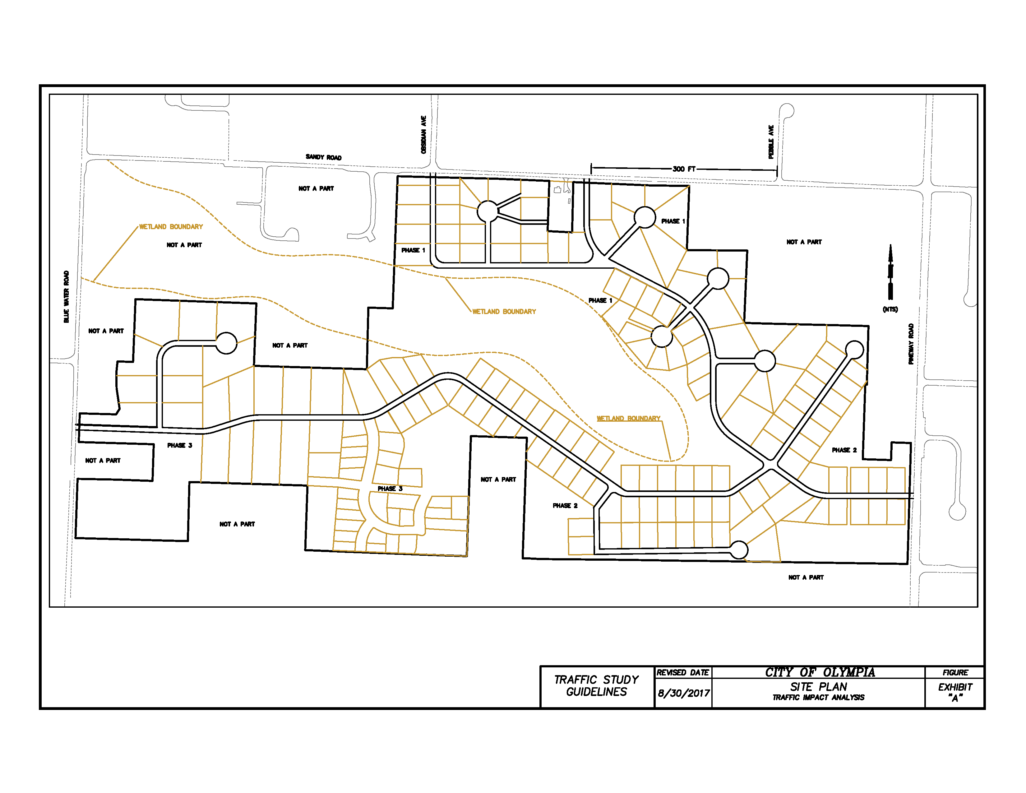
EXHIBIT “B” – VICINITY MAP TRAFFIC IMPACT ANALYSIS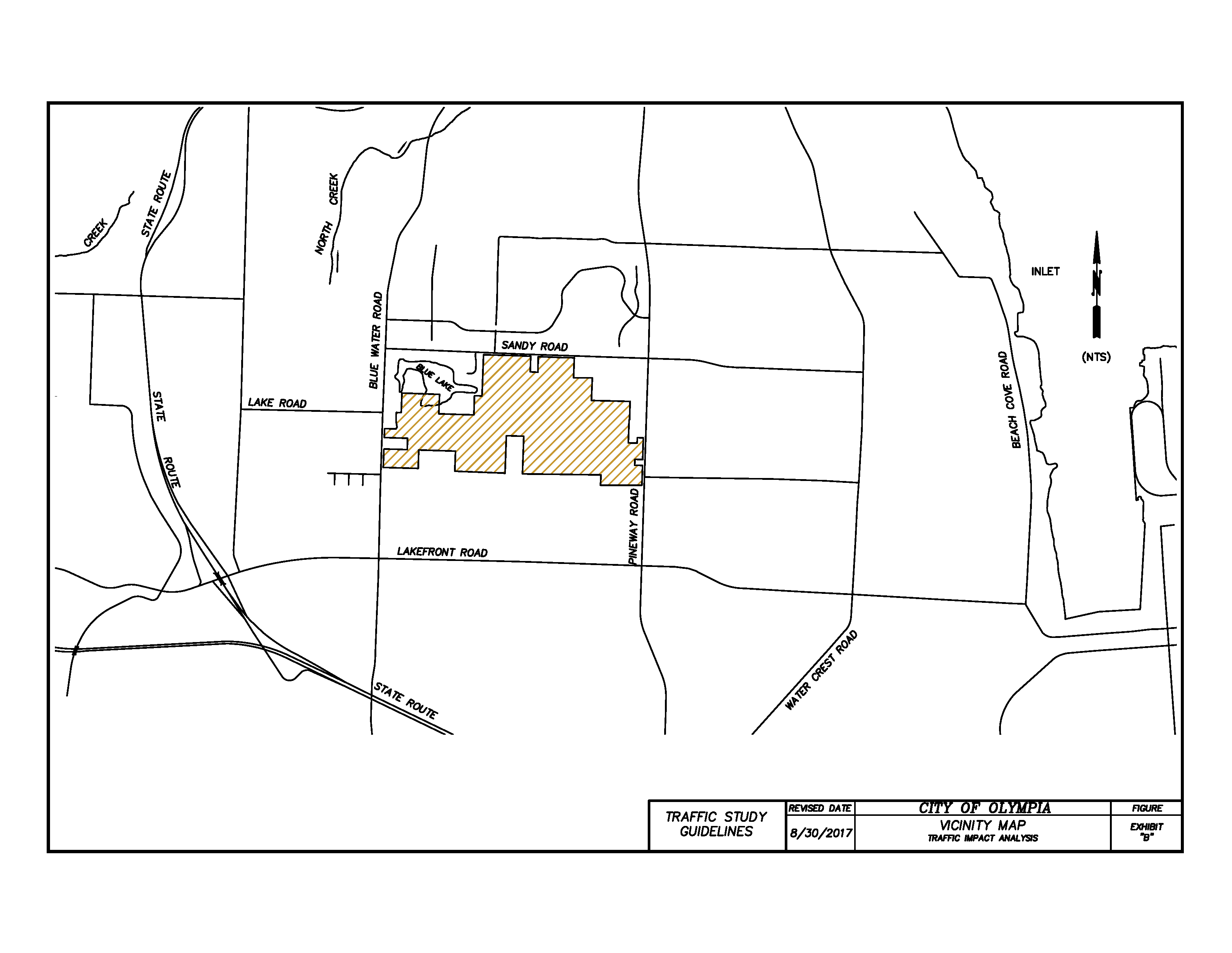
EXHIBIT “C” – EXISTING P.M. PEAK HOUR AND AVERAGE DAILY TRAFFIC VOLUMES TRAFFIC IMPACT ANALYSIS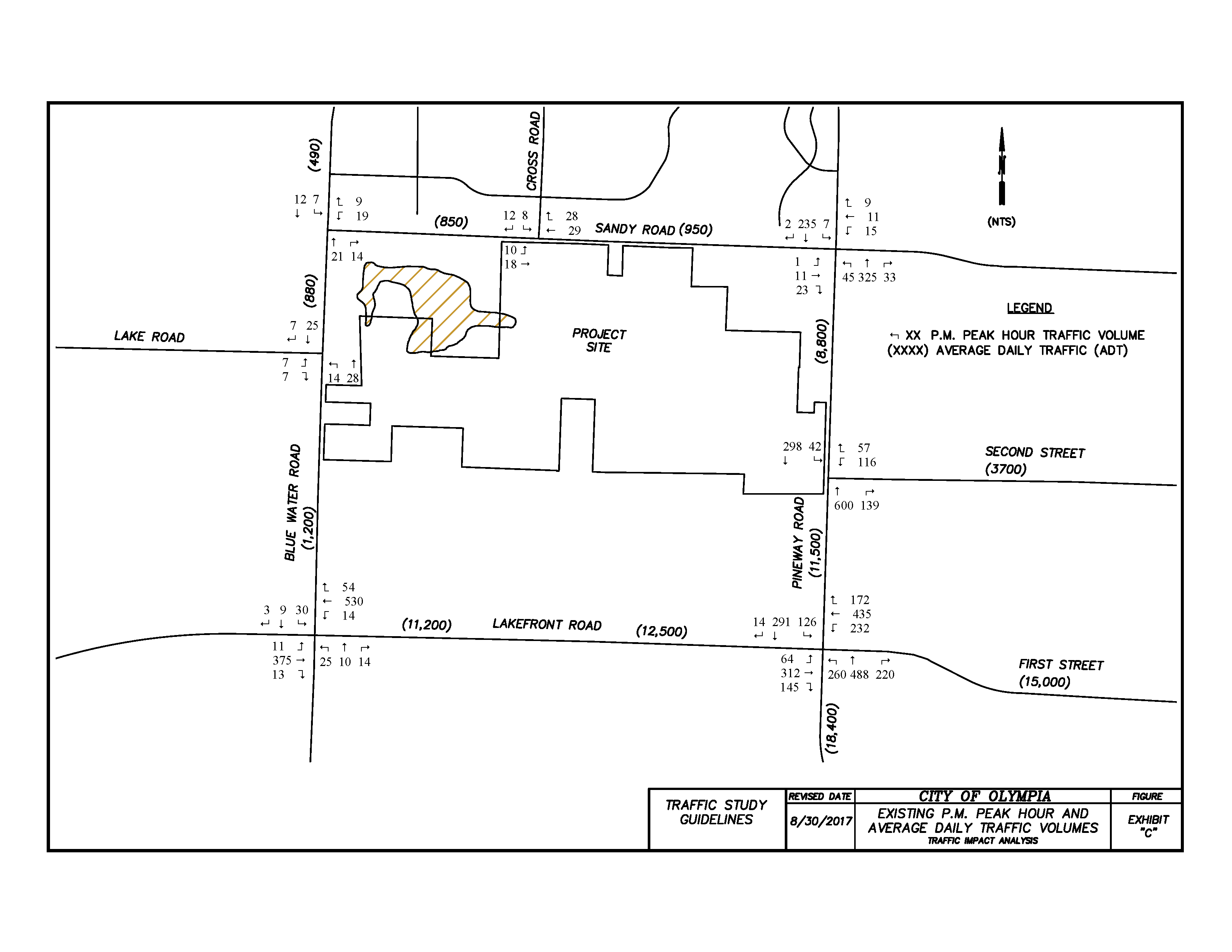
EXHIBIT “D” – PHASE 1 SITE-GENERATED P.M. PEAK HOUR AND AVERAGE DAILY TRAFFIC VOLUMES TRAFFIC IMPACT ANALYSIS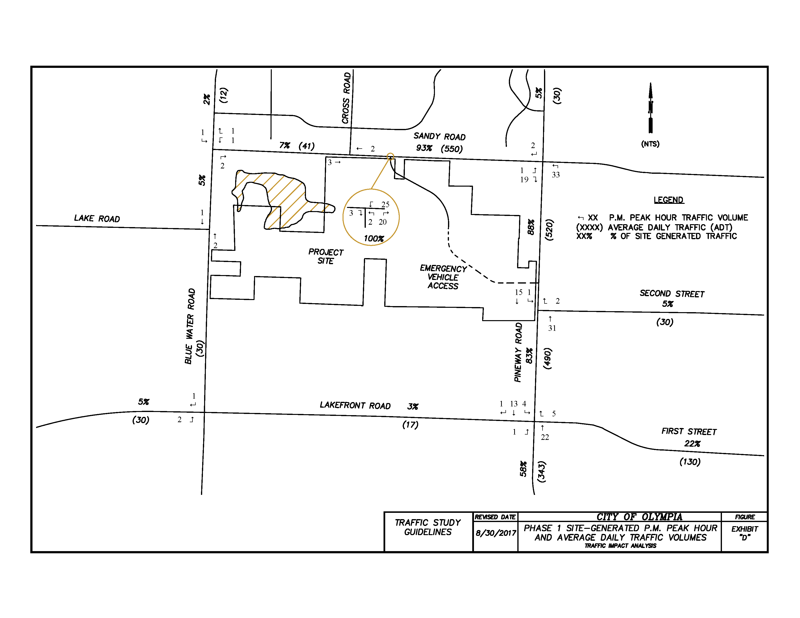
EXHIBIT “E” – TRIP DISTRIBUTION TRAFFIC IMPACT ANALYSIS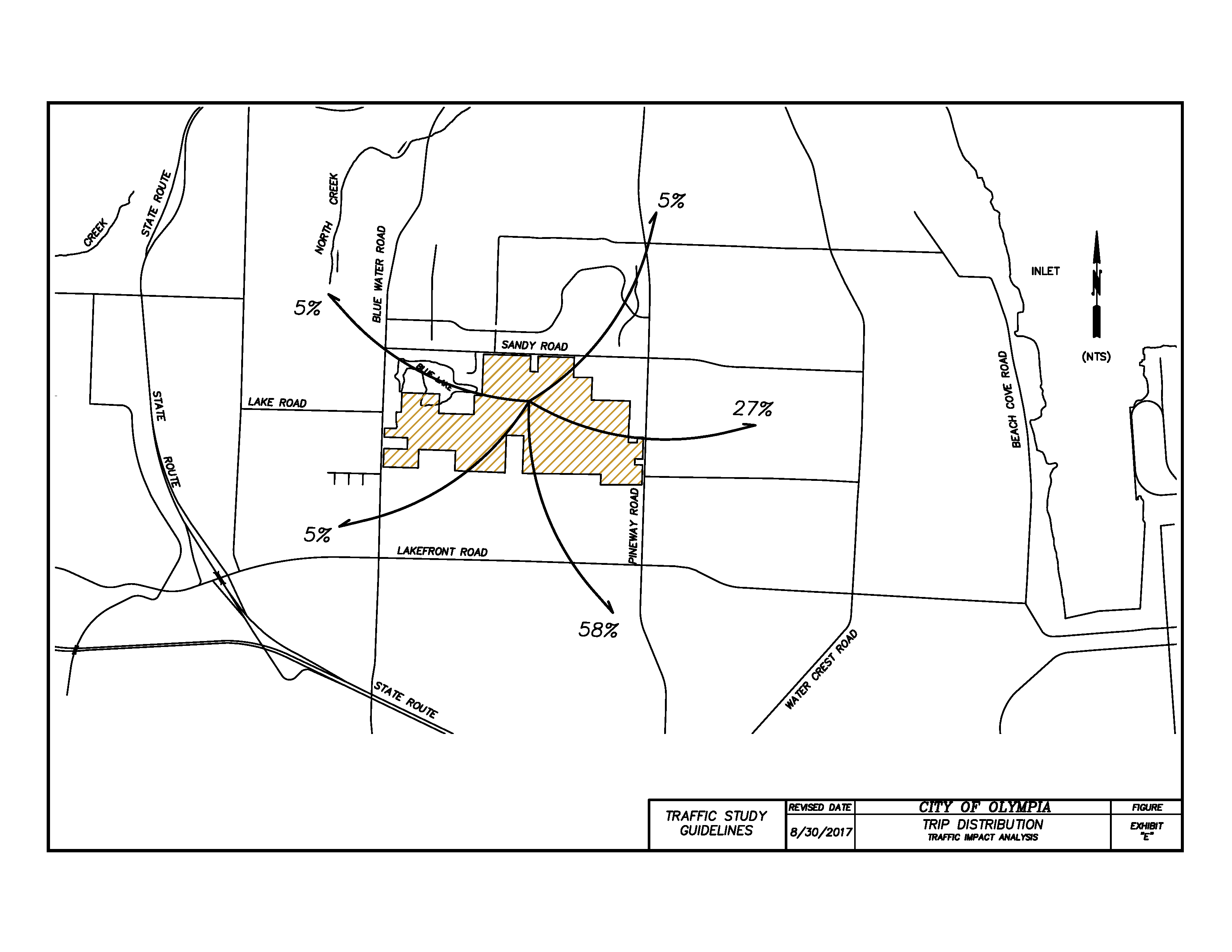
EXHIBIT “F” – PROJECTED P.M. PEAK HOUR AND AVERAGE DAILY TRAFFIC VOLUMES WITH PHASE 1 TRAFFIC IMPACT ANALYSIS