


Chapter 14.60
URBAN VILLAGE DESIGN STANDARDS
Sections:
14.60.010 Site and building design.
14.60.030 Facade articulation.
14.60.050 Service areas and mechanical equipment.
14.60.060 Roofline modulation.
14.60.010 Site and building design.
In addition to the provisions of Section 14.40.040, proposed uses shall conform to the following site and building design standards. (Ord. 20-625 § 2 (Exh. B), 2020)
14.60.020 Building massing.
A. Buildings over thirty feet in height must distinguish a "base" at ground level using articulation and materials such as stone, masonry, or decorative concrete.
B. The "top" of the building must emphasize a distinct profile or outline with elements such as projecting parapet, cornice, upper-level setback, or pitched roofline.
C. For buildings over sixty feet in height, the "middle" of the building may be distinguished from the top and base by a change in materials or color, windows, balconies, step-backs, and signage.
D. An alternate design for massing and articulation may be approved under Section 14.40.170, provided the design reduces the apparent bulk of multi-story buildings and maintains pedestrian scale.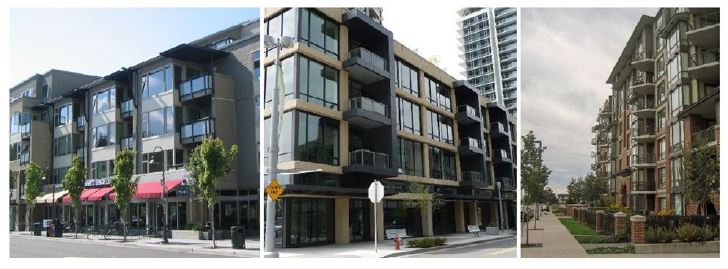
(Ord. 20-625 § 2 (Exh. B), 2020)
14.60.030 Facade articulation.
A. All buildings must include facade articulation features at maximum-specified intervals to create a human-scaled pattern. These standards apply to building elevations facing streets, open space and parks, access corridors, and residential zones.
1. Maximum Horizontal Facade Articulation Intervals.
a. Primary streets containing storefronts and residential frontages: thirty feet.
b. Residential frontages: the width of the dwelling units inside the building (e.g., if the units are twenty-five feet wide, the facade articulation must be twenty-five feet wide).
2. Articulation Features. At least three of the following articulation features must be employed for all buildings in compliance with the maximum specified facade articulation intervals:
a. Use of a window fenestration pattern.
b. Use of weather protection features.
c. Use of vertical piers/columns (applies to all floors of the facade, excluding upper level step-backs).
d. Change in roofline per Section 14.60.060.
e. Change in building material and/or siding style (applies to all floors of the facade, excluding any upper-level step-backs).
f. Vertical elements, such as a trellis with plants, green wall, or art element, that meet the purpose of the standard.
g. Providing vertical building modulation of at least twelve inches in depth if tied to a change in roofline per subsection (A)(2)(d) of this section or a change in building material, siding style, or color. Balconies may be used to qualify for this option if they are recessed or projected from the facade by at least eighteen inches.
h. Other design techniques that effectively reinforce a pattern of articulated facades compatible with the building’s surrounding context.
B. Departures will be considered, provided they meet the purpose of the standards and the building design details set forth below. For example, a departure may propose a design with only two articulation features instead of three and/or the articulation features exceed the maximum articulation interval.
Facade articulation examples.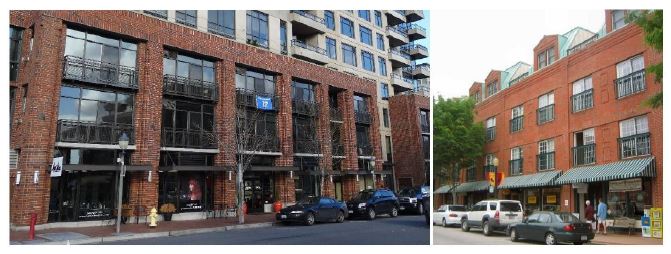
(Ord. 20-625 § 2 (Exh. B), 2020)
14.60.040 Building details.
A. Facade Details--Nonresidential and Mixed-Use Buildings. All building facades and other building elevations facing parks, pedestrian-oriented spaces, and containing primary building entrances must be enhanced with appropriate details. All new buildings must employ at least one detail element from each of the three categories listed below:
1. Window and/or entry treatment, such as:
a. Transom windows.
b. Roll-up windows/doors.
c. Recessed entry.
d. Decorative door.
e. Other decorative or specially designed window or entry treatment that meets the purpose of the standards.
Figure 14.60.040(A)(1)
Examples of decorative or specially designed windows and entries.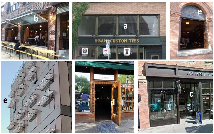
Examples of decorative or specially designed windows and entries. Upper left (b) = openable storefront window. Center top (a) = transom windows. Upper right (e) = openable window with decorative details. Lower left (e) = decorative window shades. Bottom middle (d) = decorative door. Bottom right (c) = recessed entry.
2. Building elements and facade details, such as:
a. Custom-designed weather protection element such as a steel canopy, glass, or retractable awning. Custom-designed cloth awnings may be counted as a detail, provided they are constructed of durable, high-quality material.
b. Decorative building-mounted light fixtures.
c. Bay windows, trellises, towers, and similar elements.
d. Other details or elements that meet the purpose of these standards.
Figure 14.60.040(A)(2)
Examples of attached elements that enhance the visual intrigue of the building.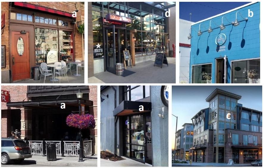
Examples of elements attached to facades that enhance the visual intrigue of the building. Upper left (a) = rigid and retractable awnings. Top center (d) = custom hanging bike rack and repair station integrated as a storefront design element. Upper right (b) = decorative lighting fixtures. Lower left and middle (a) = custom decorative canopy. Lower right (c) = decorative tower.
3. Building materials and other facade elements, such as:
a. Use of decorative building materials/use of building materials. Examples include decorative use of brick, tile, or stonework.
b. Decorative kickplate, pilaster, base panel, or other similar feature.
c. Handcrafted material, such as special wrought iron or carved wood.
d. Other details that meet the purpose of the standards.
Figure 14.60.040(A)(3)
Examples of building material details that enhance the visual intrigue of the building.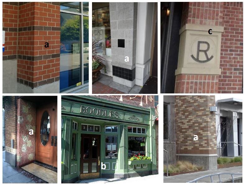
Examples of decorative surface materials. The letters match the detail options in subsection (A)(3) of this section.
4. Departures for facade detail standards of this subsection will be considered, provided the facade (at the overall scale and at the individual articulation scale) meets the purpose of the standards.
B. Window Design Standards.
1. All residential building windows must be recessed by at least two inches from the facade to add depth and richness to the building. Other design treatments to windows that add depth, richness, and visual interest to the facade will be considered.
2. Highly reflective glass must not be used on more than ten percent of a building facade or other building elevations facing parks and containing primary building entrances.
Figure 14.60.040(B)
Acceptable and unacceptable window design examples.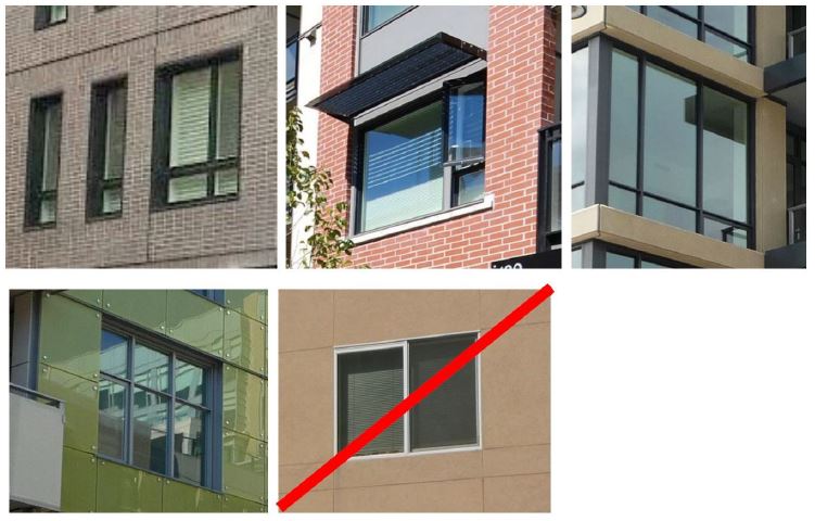
C. Articulated Building Entries. The primary building entrance for an office building, hotel, apartment building, public or community-based facility or other multi-story commercial building must be designed as a clearly defined and demarcated standout architectural feature of the building. Such entrances must be easily distinguishable from regular storefront entrances on the building. Such entries must be scaled proportional to the building. See Figure 14.60.040(C) below for good examples.
Figure 14.60.040(C)
Acceptable building entry examples.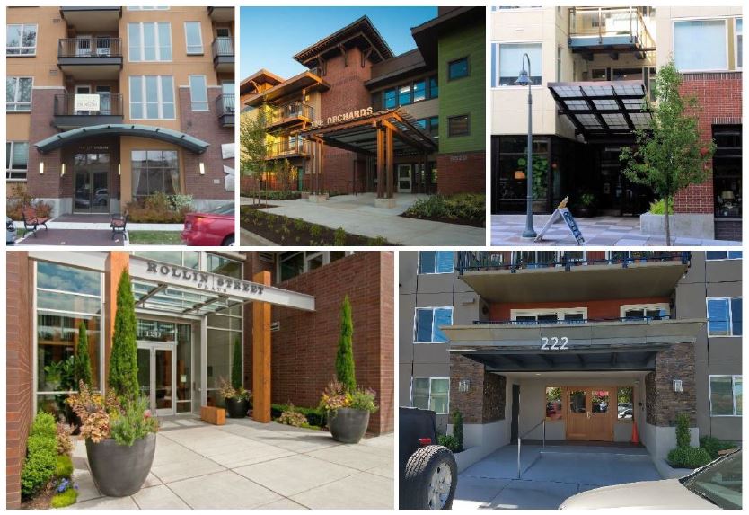
(Ord. 20-625 § 2 (Exh. B), 2020)
14.60.050 Service areas and mechanical equipment.
A. Location of Ground-Related Service Areas and Mechanical Equipment.
1. Service areas (loading docks, trash dumpsters, compactors, recycling areas, electrical panels, and mechanical equipment areas) must be located for convenient service access while avoiding negative visual, auditory, olfactory, or physical impacts on the streetscape environment, pedestrian-oriented spaces, uses within the development, and adjacent residential properties.
2. Exterior Loading Areas. Exterior loading areas for commercial uses must not be located within twenty feet of a residentially zoned property.
3. Service areas must not be visible from the sidewalk and adjacent properties. Where the Director finds that the only option for locating a service area is an area visible from a street, internal pathway or pedestrian area, or from an adjacent property, the area must be screened with structural and/or landscaping screening measures provided in this section.
4. Design for Safety. Other provisions of this section notwithstanding, service areas used by residents must be located to avoid entrapment areas and other conditions where personal security is potentially a problem. The Director may require pedestrian-scaled lighting or other measures to enhance security.
5. Locate and/or shield noise-producing mechanical equipment such as fans, heat pumps, etc., to minimize sounds and reduce impacts at property lines adjacent to residential properties.
6. Dumpster Storage Areas.
a. Dumpster storage areas must be provided for all nonresidential and multifamily development.
b. Dumpster storage areas must be on site and must not be located in the public right-of-way.
c. Dumpster storage areas must be sized to accommodate the minimum dumpster sizes (as required by the applicable utility provider) for garbage, recycling, and composting.
B. Screening of Ground-Related Service Areas and Mechanical Equipment. Service elements are encouraged to be integrated within the structure. Where they are not provided within the structure, the elements shall be screened consistent with the following standards:
1. Structural enclosures must be constructed of masonry, heavy-gauge metal, or decay-resistant material that is also used with the architecture of the main building. The reviewing authority may allow materials other than those used for the main building if the finishes are similar in color and texture or if the proposed enclosure materials are more durable than those for the main structure. The walls must be sufficient to provide full screening from the affected roadway, pedestrian areas or adjacent use.
2. Gates must be made of heavy-gauge, site-obscuring material. Chain link or chain link with slats is not an acceptable material for enclosures or gates.
3. Where the interior of a service enclosure is visible from surrounding streets, pathways, and buildings, an opaque or semi-opaque horizontal cover or screen must be used to mitigate unsightly views. The horizontal screen/cover should be integrated into the enclosure design (in terms of materials and/or design).
4. Collection points must be located and configured so that the enclosure gate swing does not obstruct pedestrian or vehicular traffic or does not require that a hauling truck project into any public right-of-way. Ensure that screening elements allow for efficient service delivery and removal operations.
5. The service area must be paved.
6. The sides and rear of service enclosures must be screened with landscaping at least five feet wide in locations visible from the street, parking lots, and pathways to soften views of the screening element and add visual interest.
C. Utility Meters, Electrical Conduit, and Other Service Utility Apparatus. These elements must be located and/or designed to minimize their visibility to the public. Project designers are strongly encouraged to coordinate with applicable service providers early in the design process to determine the best approach in meeting these standards. If such elements are mounted in a location visible from the street, pedestrian path, shared open space, or shared auto courtyards, they must be screened with vegetation and/or integrated into the building’s architecture.
Figure 14.60.050(C)
Utility meter location and screening – Good and bad examples.
Place utility meters in less visible locations. The lower left example is successfully tucked away in a less visible location and screened by vegetation. The right image is poorly executed and would not be permitted in such visible locations (along the sidewalk). Such meters must be coordinated and better integrated with the architecture of the building.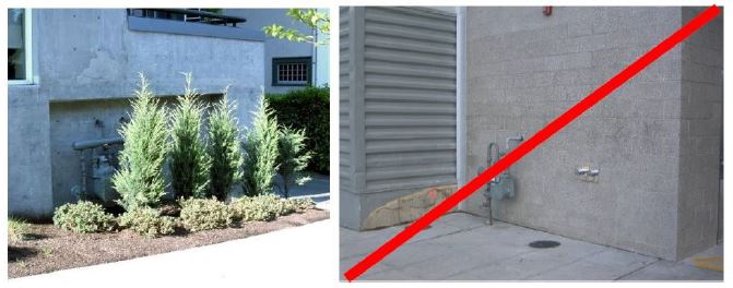
D. Rooftop Mechanical Equipment. Rooftop mechanical equipment (HVAC) must be screened by an extended parapet wall or other roof forms that are integrated with the architecture of the building.
Figure 14.60.050(D)
Examples of how to screen roof-mounted mechanical equipment.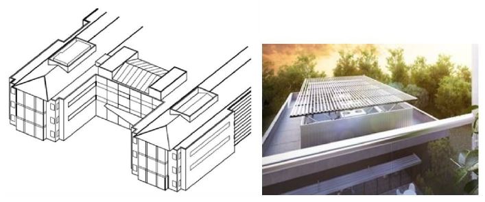
(Ord. 20-625 § 2 (Exh. B), 2020)
14.60.060 Roofline modulation.
A. Roofline modulation is encouraged, and it can be used as one of the facade articulation features in Section 14.60.030(A)(2). In order to qualify as an articulation feature, rooflines must employ one or more of the following:
1. For flat roofs or facades with a horizontal eave, fascia, or parapet, the minimum vertical dimension of roofline modulation is the greater of two feet or 0.1 multiplied by the wall height (finish grade to top of the wall) when combined with vertical building modulation techniques described in subsections above. Otherwise, the minimum vertical dimension of roofline modulation is the greater of four feet or 0.2 multiplied by the wall height.
2. A pitched roofline or gabled roofline segment of at least twenty feet in width. Buildings with pitched roofs must include a minimum slope of 5:12 and feature modulated roofline components at the interval required per the applicable standard above.
3. A combination of the above.
B. Departures will be considered, provided the roofline modulation design effectively reduces the perceived scale of the building and adds visual interest.
Figure 14.60.060(1)
Acceptable examples of roofline modulation.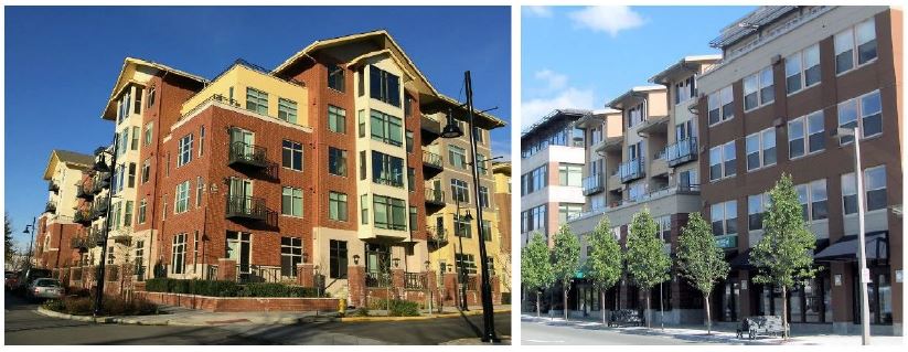
(Ord. 20-625 § 2 (Exh. B), 2020)
14.60.070 Signage standards.
A. Signs must fit with the overall architectural character, proportions, and details of the development.
B. The base of any freestanding, pole, ground, or monument sign must be planted with shrubs or seasonal flowers.
C. Electronic reader boards and signs that include flashing, chasing, moving, or animation are prohibited.
D. Freestanding or pole signs located along adjacent streets may be permitted if they meet the following criteria:
1. No more than fifteen feet in height;
2. Designed with two poles placed at the outermost sides of the sign face;
3. No more than forty-five square feet in sign area per face; and
4. Constructed of materials matching one or more buildings located on the site. (Ord. 20-625 § 2 (Exh. B), 2020)