


Division 13-09-002
Sewer System Design
Sections:
13-09-002-0001 Guide for Design
13-09-002-0002 Wastewater Design Flows
13-09-002-0002.1 Peak Flows
13-09-002-0003 Sewer Design Capacities
13-09-002-0004 Minimum Pipe
13-09-002-0005 Velocities of Flow
13-09-002-0006 Alignment
13-09-002-0007 Design and Spacing of Manholes
13-09-002-0008 Design of Deep Sewer Lines
13-09-002-0009 Private Sewer Lines
13-09-002-0010 Sewer Services
13-09-002-0011 Sewer Mains
13-09-002-0012 Private Pressure Sewer Mains and Services
13-09-002-0012.1 Lift Stations
13-09-002-0012.2 Wastewater Force Mains
13-09-002-0012.3 Force Main Discharge Manholes
13-09-002-0012.4 Private Pressure Wastewater Systems
13-09-002-0013 On-Site Disposal Systems
13-09-002-0001 Guide for Design
A. Arizona Revised Statutes establishes the control for the design, construction, and operation of sewage systems and waste treatment works to be with the Arizona Department of Environmental Quality (ADEQ). Engineering bulletins produced by ADEQ are to serve as guides for designs of sewage systems. These include, but are not limited to:
1. Bulletin No. 11 - Minimum Requirements for Design, Submission of Plans and Specification of Sewage Works.
2. Bulletin No. 12 - The Septic Tank.
3. Bulletin No. 15 - Package Aeration Plants.
B. More restrictive criteria of design stated in these regulations shall take precedence over ADEQ criteria.
C. Proposed public sewer systems must be gravity flow. No public sewer lift stations will be permitted within the City system. (Ord. 2017-22, Rep&ReEn, 07/05/2017)
13-09-002-0002 Wastewater Design Flows
A. Design flows utilized in the preparation of engineering design reports, plans and specifications shall conform to the criteria set forth in this section as a minimum.
B. Average daily flow estimates based on land use, shall conform to Table 13-09-002-01, Average Daily Flows by Land Use. Where the project land use does not fit within the tabulated categories, an average daily unit flow of one hundred (100) gallons per person per day shall be used.
|
LAND USE |
AVERAGE DAILY FLOW |
|
|---|---|---|
|
Type |
|
Average dry weather flow (ADWF) |
|
Residential Single-Family, Townhouses |
Use 3.5 persons per dwelling unit |
75 gallons per capita per day (gpcd) |
|
Residential Manufactured Homes, Mobile Homes |
Use 3.0 persons per dwelling unit |
75 gallons per capita per day (gpcd) |
|
Residential Condos, Apartments |
Use 2.5 persons per dwelling per unit |
75 gallons per capita per day (gpcd) |
|
Hotel, Motel Tourist |
Use 2.0 persons per hotel/motel room |
75 gallons per capita per day (gpcd) |
|
Commercial |
Use number of acres |
1,000 gallons per acre per day (gad) 3,000 gad PEAK |
|
Industrial |
Domestic flows only |
1,000 gallons per acre per day (gad) 3,000 gad PEAK |
|
Schools, Colleges |
Use enrollment per building |
90 gallons per capita per day (gpcd) |
|
Factors are based on average dry weather flow (ADWF) from City of Flagstaff "Wastewater Management System Facility Plan," prepared by Brown and Caldwell Engineers. |
||
(Ord. 2017-22, Rep&ReEn, 07/05/2017)
13-09-002-0002.1 Peak Flows
All gravity sewer mains shall be designed for peak flow conditions. Peak flow is calculated as the product of the peaking factor and the average daily flow. The peaking factor should be obtained from Figure 13-09-002-01, Ratio of Peak Flow to Dry Weather Flow, based on population.
Figure 13-09-002-01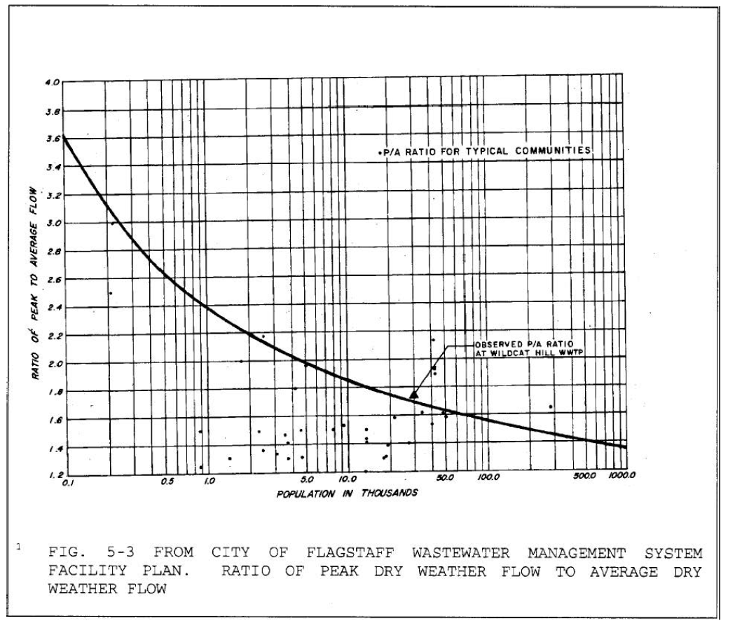
(Ord. 2017-22, Rep&ReEn, 07/05/2017)
13-09-002-0003 Sewer Design Capacities
Sewer systems, trunk lines, and out-fall lines are to be designed to service the ultimate density of the drainage area. Capacities of lines are to be determined for an entire drainage area, developed or undeveloped, which may be reasonably serviced by the proposed system or by future extensions of the system. Densities will be estimated from the land use plan of the current Regional Land Use and Transportation Plan. Use Table 13-09-002-01, to determine number of persons per unit for different dwelling types. All sewer lines must be designed for peak flow in accordance with Table 13-09-002-01 and Figure 13-09-002-01. The maximum ratio of the depth of flow to the diameter of the pipe, (d/D), shall be seventy percent (70%). (Ord. 2017-22, Rep&ReEn, 07/05/2017)
13-09-002-0004 Minimum Pipe
Gravity sewer lines shall be sized to accommodate the peak design flow subject to the following limitations:
A. The d/D ratio for gravity sewer pipes shall be no greater than seven-tenths (0.7) at the peak flow condition.
B. Minimum pipe size shall be eight (8) inches in diameter.
C. A maximum of one hundred twenty (120) acres of combined commercial and residential development shall drain into an eight (8) inch diameter line. (Ord. 2017-22, Rep&ReEn, 07/05/2017)
13-09-002-0005 Velocities of Flow
A. Velocities in sewer lines shall be determined for design capacities using Mannings formula V = (u/n) (R)2/3 (S)1/2 where V is the average velocity (fps, m/s), u is 1.49 for English units and one (1) for Metric units, n is the Mannings roughness coefficient (as appropriate for the pipe to be used), R is the hydraulic radius (ft), S is slope in (ft/ft).
B. Design velocities are to be within the range of two (2) fps to ten (10) fps flowing full.
1. A minimum velocity of two and one-half (2.5) fps is recommended in order to prevent deposition. The following chart is a guideline for the limits of slope for smaller diameters based on velocity and the n value for the pipe flowing full condition. Capacity must also be considered.
|
Pipe Size (inches) |
Min. Slope (%) 2 fps** |
Max. Slope (%) 10 fps* |
||
|---|---|---|---|---|
|
|
n = 0.013 |
n = 0.010 |
n = 0.013 |
|
|
8 |
0.34 |
4.91 |
8.29 |
|
|
10 |
0.26 |
3.65 |
6.16 |
|
|
12 |
0.20 |
2.86 |
4.83 |
|
|
15 |
0.15 |
2.12 |
3.59 |
|
* PVC (n = 0.010) DIP (n= 0.013)
** Minimum slopes for PVC shall also be calculated using a coefficient of roughness of 0.013.
(Ord. 2017-22, Rep&ReEn, 07/05/2017); Ord. 2024-13, Amended, 4/16/2024 (Res. 2024-15)
13-09-002-0006 Alignment
Sewers shall be laid with straight alignments between manholes. Curvilinear sewers are not permitted. Straight alignment shall be checked by using a laser beam. Sewers shall be located in street right-of-way (ROW) and shall generally run parallel to property lines or street centerline and located out of the wheel path (preferably in the center of the street). Gravity sewer alignments shall be located as set forth in the latest edition of standard utility locations for the City of Flagstaff Engineering Details. (Ord. 2017-22, Rep&ReEn, 07/05/2017)
13-09-002-0007 Design and Spacing of Manholes
A. Manholes are to be installed at the end of each line; at all changes in grade, size, horizontal or vertical alignment; at all intersections of mains and service connections greater than six (6) inches in diameter; and at distances not greater than four hundred (400) feet for sewers twelve (12) inches or less, and five hundred (500) feet for sewers greater than twelve (12) inches.
|
PIPE SIZE (INCHES) |
MAXIMUM MANHOLE SPACING (FEET) |
|---|---|
|
Less than 12" |
400 |
|
Greater than 12" |
500 |
B. Five (5) foot diameter manholes are required wherever the sewer main diameter is twelve (12) inches or greater, whenever there are two (2) or more inlets, whenever the manhole depth is twelve (12) feet or greater or whenever the manhole is designed with a drop sewer connection. Clean-outs are not allowed.
|
PIPE SIZE (INCHES) |
MANHOLE DEPTH (FT) |
MANHOLE DIAMETER (INCHES) |
FRAME AND COVER DIAMETER (INCHES) |
|---|---|---|---|
|
Less than 12" |
12 and less |
48 |
24 |
|
Greater than 12" |
Greater than 12 |
60 |
30 |
|
15" and larger |
Any |
60 |
30 |
|
Drop Manholes |
Any |
60 |
30 |
C. A drop manhole is to be used when a sewer enters a manhole two and one-half (2.5) feet or more above the manhole invert in accordance with MAG Detail No. 426.
1. If there is less than two and one-half (2.5) feet of fall, redesign of sewer grades is required to result in a maximum of one-half (0.5) foot above the flow line of the outlet.
2. Sewer grades shall be normally designed to provide one-tenth (0.1) foot fall from the flowline inlet to the flowline outlet within the manhole.
3. When a sewer main joins a ten (10) inch or greater main, the top of each pipe shall match at their intersection of the manhole.
a. The maximum horizontal deflection angle (inlet to outlet) for an eight (8) inch main shall be ninety (90) degrees.
b. For mains ten (10) inches and larger the maximum defection angle shall be sixty (60) degrees.
c. The minimum flow line radius shall be two (2) feet.
D. Concrete caps on manholes located outside roadways or parking lots shall have a continuous No. 3 rebar centered in the cap.
E. One (1) adjustment ring or one (1) row of bricks is required on all manholes. The ring and cover shall not be set directly on the cone.
F. Manhole covers shall have a pickhole and watertight manhole covers shall have a concealed type pickhole for removal of the cover. Bolts on watertight manhole lids shall be stainless steel.
G. Where corrosive conditions due to septicity or other causes are anticipated, consideration shall be given to providing corrosion protection on the interior of the manholes.
H. Manholes shall be pre-cast concrete or poured-in-place concrete type. Manhole lift holes and grade adjustment rings shall be sealed with non-shrinking mortar.
1. Inlet and outlet pipes shall be joined to the manhole with a gasketed, flexible water-tight connection or any water-tight connection arrangement that allows differential settlement of the pipe and manhole wall to occur.
I. Watertight manhole covers shall be used whenever the manhole is located in a floodplain, wash, or other areas known to be subject to stormwater runoff.
J. Locked manhole covers may be required in isolated easement locations or where vandalism is anticipated.
K. When connecting to an existing manhole, coring will not be accepted. The connection shall be made with a new cast-in-place manhole.
L. Manholes should be located outside of sidewalks, bikeways, bike lanes, and FUTS trails when feasible. (Ord. 2017-22, Rep&ReEn, 07/05/2017; Ord. 2024-13, Amended, 4/16/2024 (Res. 2024-15))
13-09-002-0008 Design of Deep Sewer Lines
When the depth of a sewer line exceeds fifteen (15) feet, then: services will not be allowed; the pipe must be class 350 ductile iron or designed to withstand the trench and traffic loads; and, an easement wider than twenty (20) feet may be required. Sewer lines deeper than twenty-five (25) feet will not be allowed. (Ord. 2017-22, Rep&ReEn, 07/05/2017)
13-09-002-0009 Private Sewer Lines
Private sewer mains shall not be allowed. Existing private sewer mains shall be maintained as required and regulated by the Arizona Department of Environmental Quality. (Ord. 2017-22, Rep&ReEn, 07/05/2017)
13-09-002-0010 Sewer Services
A. Sewer services shall be installed perpendicular (not parallel) to the right-of-way or easement, within the right-of-way or easement, and shall not be installed across another parcel or lot except where service is perpendicular to, and entirely within, a public utility or sewer easement. Private easements across separate parcels will not satisfy the requirements of this section. Sewer services are prohibited on sewer transmission mains that are eighteen (18) inches or larger.
B. Sewer service locations shall be located by branding an "S" on the top or face of the curb.
C. Sewer services shall be located a minimum of five (5) feet from the outside of a manhole wall.
D. An approved backwater valve shall be installed when the finished floor elevation of a building is one (1) foot or less above the nearest upstream manhole or clean-out rim elevation. A self-explanatory tabulated numerical listing of the lots requiring backwater valves shall appear on the plans. The backwater valves shall not be installed within a public right-of-way or easement.
E. If sewer services are installed via saddles, the minimum spacing between services shall be five (5) feet, and there shall be one (1) connection per length of VCP and two (2) per length of PVC main.
F. When a sewer service is required to be abandoned, it shall be abandoned at the property line and capped using the appropriate material (PVC, clay, or concrete). (Ord. 2017-22, Rep&ReEn, 07/05/2017; Ord. 2024-13, Amended, 4/16/2024 (Res. 2024-15))
13-09-002-0011 Sewer Mains
A. Where reasonable, sewer mains shall be located under a paved surface. Where this is not possible, the engineer should give consideration to access and maintenance issues. The engineer should examine the possibility of redesigning and the project layout, e.g., roads, building envelopes, and drainage patterns, in order to facilitate access and maintenance to all sewer pipes and appurtenances with the appropriate equipment and vehicles for repairs and/or preventive maintenance operations.
B. Dead end easements shall be avoided unless they are for a sewer which has no potential for future extension.
C. Manholes shall be located in the right-of-way or an easement which provides access for emergency response, repairs, and/or preventative maintenance operations.
D. Sewer lines constructed in washes and floodways shall have their crowns at least two (2) feet below the one hundred (100) year storm scour depth and shall be constructed with DIP. The DIP shall extend a minimum of ten (10) feet each side of the one hundred (100) year storm scouring. (Ord. 2017-22, Rep&ReEn, 07/05/2017)
13-09-002-0012 Private Pressure Sewer Mains and Services
A. All proposed public wastewater systems shall be gravity flow within the gravity wastewater shed of the Wildcat Hill Wastewater Treatment Plant (see Figure 13-09-002-02 for a map of the gravity wastewater shed of the Wildcat Hill Wastewater Treatment Plant). Public pressure wastewater systems including pressure piping, lift stations, and appurtenances are prohibited within this area.
B. Where pressure systems are allowed, they will transition back to gravity as soon they cross into the gravity wastewater shed as shown in Figure 13-09-002-02.
Figure 13-09-002-02 Gravity Wastewater Shed of Wildcat Hill
Wastewater Treatment Plant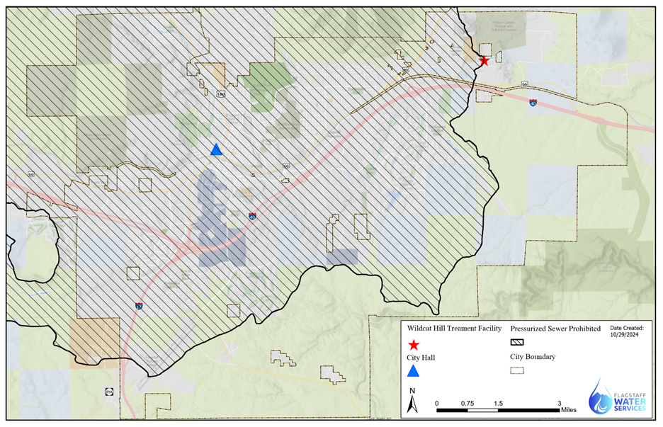
C. All proposed designs shall meet requirements of A.A.C. Title 18, Chapter 9. (Ord. 2017-22, Rep&ReEn, 07/05/2017; Ord. 2025-03, Amended, 03/04/2025)
13-09-002-0012.1 Lift Stations
A. A development agreement will be required for any new development that requires a lift station.
1. The development agreement shall include a payment of ten (10) years’ operation and maintenance which will be included on the Estimate of Probable Cost submitted for the project. The payment will be collected before the issuance of the public improvements permit.
B. The location of the lift station should be chosen so that the entire lift station drainage area can be served by gravity up to the lift station. Lift station sites may not be located in floodways, floodplains or other locations subject to inundation. The lift station must be accessible and free of inundation during the one hundred (100) year flood event.
C. Design should accommodate for expansion of lift station capacity with development while meeting wet well retention and pump cycling/capacity criteria. Capacities of lines are to be determined for an entire drainage area, developed or undeveloped, which may be reasonably serviced by the proposed system or by future extensions of the system. Densities will be estimated from the land use plan of the current Regional Plan. Use Table 13-09-002-01 to determine number of persons per unit for different dwelling types. All lift stations and force mains must be designed for peak flow in accordance with Table 13-09-002-01 and Figure 13-09-002-01.
D. Minimum design considerations by the Water Services Division for lift station facilities are as follows:
1. A communications link will be provided by fiber optic cable to the nearest City facility if the facility is within one (1) mile of the lift station. If the facility is greater than one (1) mile away from the site, then a microwave tower may be constructed instead of the fiber optic cable. A SCADA communications plan must be submitted for plan approval.
a. All components of the SCADA system shall be included in the communications plan including at a minimum monitoring instruments, programmable logic controllers (PLCs), remote terminal unit (RTUs) and variable frequency drives (VFDs). These components shall be compatible with the existing COF SCADA system.
2. An outflow meter will be provided at the lift station. Meters will be submitted and approved by the Water Services Division. The outflow meter shall be an ultrasonic flow meter that is compatible with COF SCADA systems. The flow meter shall be sized to meet both low and high flow ranges per manufacturer recommendations. The flow meter shall be located in a vault easily accessible and visible within the site. The flow meter shall have a pressure rating greater or equal to the pipeline it is connected to, and shall be rated for wastewater.
3. An alarm with an automated callout system will be required. The system will be submitted and approved by the Water Services Department. The alarm and automated callout system shall be functional before acceptance of the wastewater system. An override button shall be provided at the lift station site to allow for maintenance to be completed without triggering alarms.
4. The lift station shall be equipped with a standby power system. This system shall include at a minimum, an automatic transfer switch, a diesel generator, and a fuel tank of sufficient capacity to allow continuous operation under full load for twenty-four (24) hours.
5. Design shall allow for continuity of pumping operation during service and cleaning through the incorporation of bypass pumping connections that allow the main wet well to be bypassed for maintenance other design as approved by the City Engineer and Water Services Director.
a. A cleanout pipe will be provided that allows for a vacuum truck to connect and clean the lift station.
6. All pumps must be submitted and approved by COF Water Services Division. Minimum design requirements for pumps are as follows:
a. Nonclog submersible wastewater pumps shall be used for the lift station.
b. The pump will require at least one (1) backup for redundancy. The pump system shall be set up so that both pumps are regularly operated using a duplex system or similar system that balances the wear on the pumps.
c. Pumps shall be designed with a rail system and hoist to allow for the pumps to be easily lifted and lowered into the wet well for pump replacements.
7. All lift interior lift stations components shall be coated with a corrosion-resistant epoxy coating rated for wastewater.
8. Check valves, air release valves, plug valves, and flow meters shall be located in a separate vault within the lift station.
a. Check valves shall be full-port solids handling ball check valves. Check valves shall be provided on pump discharges 8” and smaller. Check valves shall be rated for wastewater and feature a corrosion resistant epoxy coating. Check valves shall have a pressure rating equal to or greater than the pipeline they are connected to.
b. Air release valves shall be combination type and rated for wastewater. Air release valves shall be Cla-Val or approved equal.
c. Eccentric plug valves shall be provided on the discharge of all pumps. Install the plug valves horizontally so the plug rotates up ninety (90) degrees to open and the plug seat is facing downstream when closed. The plug valves shall be located downstream of the check valves. All valve materials shall be rated for wastewater and shall have a minimum of forty (40) mils of ceramic epoxy lining.
9. Fall protection shall be provided at the wet well entry hatch.
10. An odor control system shall be required. The odor control system must be submitted and approved by the Water Services Division.
11. A minimum eight (8) foot tall CMU masonry wall around the perimeter with a locked entrance gate.
a. The wall shall be compatible with the surrounding environment, including landscaping.
12. The facility entrance shall have a twelve (12) foot wide double drive access gate with at least twelve (12) feet clear space.
13. The station shall have a paved access road at least twelve (12) feet wide with a maximum slope not to exceed ten percent (10%)
a. A forty-five (45) foot radius or hammerhead turnaround shall be provided if the access road exceeds fifty (50) feet in length.
14. The interior of the compound shall be surfaced with four (4) inches of asphaltic cement pavement.
15. Service vehicle access to major station components shall be incorporated in the station design.
16. Downcast facility lighting, both wall mounts and pole mounts, shall be provided with at least one (1) photocell-operated light.
a. The light switch shall be located next to the access gate in the interior of the compound.
b. Lights shall be dark sky compliant.
E. An operation and maintenance plan for the lift station and its components must be provided and approved by COF Water Services Division. The operation and maintenance plan shall be provided for all equipment and systems, valves, instruments and control devices, and electric gear. The operation and maintenance plans shall include at a minimum:
1. Contact information for the contractor, engineer, and supplier;
2. Engineer-approved submittals;
3. Disassembly drawings;
4. Operating instructions;
5. Test data;
6. Maintenance recommendations and schedule;
7. Troubleshooting procedures;
8. Recommended spare parts;
9. Warranty terms and duration.
F. An engineer’s design report must be prepared and submitted. The report shall be prepared, signed and sealed by an Arizona registered engineer. It shall be submitted to the City for review and approval and will include, at a minimum, the following:
1. Description of design criteria to be utilized other than this document;
2. Flow computations, including a complete analysis of the downstream gravity system’s capacity to convey such flows in addition to other design flows and if mitigation measures such as gravity wastewater up-size, flow equalization basins or other measures are warranted;
3. Wet well volume calculations;
4. Retention and pump cycling calculations;
5. Hydraulic analysis including friction and minor head loss calculations;
6. Calculated system curves with overlaid pump curves;
7. Surge protection recommendations;
8. Structural component description and calculations;
9. Electrical, instrumentation, and process description, control description, and calculations;
10. Analysis and design solutions to control corrosion, odor, and noise in the lift station, force main and downstream gravity wastewater system;
11. Define site, right-of-way, and easement requirements;
12. Listing of permit requirements;
13. Geotechnical investigation;
14. Cost estimate based on unit costs for major elements of work following this design criteria. (Ord. 2025-03, Enacted, 03/04/2025)
13-09-002-0012.2 Wastewater Force Mains
A. Velocities in force mains shall be determined for design capacities using the Hazen-Williams formula. Flow capacities shall also be determined using the Hazen-Williams formula.
B. Design velocities for wastewater force mains shall comply with ARS R18-9-E301 with a minimum of three (3) and maximum of seven (7) feet per second.
C. New public wastewater force mains may be constructed using the following minimum material specification and subject to engineering analysis based on the specific design additional material specifications may apply:
1. Class 200 (polyvinyl chloride) PVC conforming to the appropriate MAG section.
2. Class 200 ductile iron pipe (DIP) conforming to the appropriate MAG section. DIP may be used for wastewater force mains, four (4) inches through twelve (12) inches in diameter. All ductile iron pipelines shall be polyethylene encased in accordance with MAG Specifications. When DIP is used, it shall be lined with Protecto 401 ceramic epoxy. Special design considerations may require a higher class rating of DIP.
3. DR 11 High density polyethylene (HDPE) wastewater pipe conforming to MAG Section 738 and AWWA C906.
D. Depth requirements for force mains shall conform to COF standards for water mains.
E. Separation requirements shall meet requirements defined in COF Engineering Standards Section 13-09-001-0004 and the current MAG standards, whichever is greater.
F. Force mains six (6) inches and larger shall provide two (2) way cleanouts every one thousand three hundred (1,300) feet or one (1) way cleanouts every six hundred fifty (650) feet. Single cleanouts must be provided at all horizontal bends oriented in line with the downstream pipe. Lines four (4) inches and smaller shall provide two (2) way cleanouts every six hundred (600) feet or one (1) way cleanouts every three hundred (300) feet.
G. Joint restraint will be required everywhere where there are horizontal or vertical bends and in areas where the pipe is above ground.
H. Air release valves will be required at all high points. (Ord. 2025-03, Enacted, 03/04/2025)
13-09-002-0012.3 Force Main Discharge Manholes
A. Force main discharge manholes should conform to City of Scottsdale Standard Detail 2402 or approved equal.
B. Discharge manholes shall at a minimum be coated with a corrosion resistant epoxy coating approved by COF Water Services. (Ord. 2025-03, Enacted, 03/04/2025)
13-09-002-0012.4 Private Pressure Wastewater Systems
A. Private pressure wastewater systems, including individual pressure wastewater services, are not allowed unless approved by the Utilities Division and the City Engineer. Off-site extensions of the public system in order to provide gravity service may be required. Should a private system be allowed, the following criteria shall be addressed prior to plan approval:
1. A provision for continued operation by the appropriate class or grade operator as required in A.A.C. Section R18-05-114.
2. A provision for scheduled routine operation and maintenance by qualified personnel and an operation and maintenance manual approved by ADEQ.
3. An emergency spill prevention and response plan shall be kept at the site and include provisions for twenty-four (24) hour response and mitigation by qualified personnel.
4. In accordance with A.A.C. Section R18-9-E301, wastewater collection, force mains, and lift stations having the design flow of ten thousand (10,000) gpd or more shall maintain and revise, when needed, an operation and maintenance plan at the operator’s control center (office) and the appropriate field person’s vehicle.
5. Private pressure systems may not be placed within public right-of-way or public utility easement. Separate private utility easements may be required.
6. When a lift station is installed as an interim condition until the future extension of a gravity main, the developer shall pay to the City Utilities Division the estimated cost of decommissioning and removing the lift station and connecting to the gravity main. (Ord. 2025-03, Enacted, 03/04/2025)
13-09-002-0013 On-Site Disposal Systems
On-site disposal systems will be permitted only as outlined in AAC R18-9-A309. On-site disposal systems shall be designed to allow immediate future ties to sewer lines when available. Percolation testing and design shall meet County Health Department and ADEQ requirements. (Ord. 2017-22, Rep&ReEn, 07/05/2017)