


CHAPTER 6.4
SEWAGE STANDARDS
ARTICLE I. PURPOSE
6.4-12 Scope and Applicability
ARTICLE II. CONNECTION TO SEWER
6.4-20 Sewer Connection Required
ARTICLE III. SUBDIVISION MAPS AND LOT LINE ADJUSTMENTS
6.4-30 Applicability and Reporting
6.4-32 Required Information and Inspections
6.4-33 On-Site Sewage Disposal System Area Requirements
ARTICLE IV. BUILDING PERMITS, NEW CONSTRUCTION, ADDITIONS, AND REPLACEMENT STRUCTURES
6.4-42 Requirement for On-Site Sewage Disposal System Installation or Modification
6.4-43 Disposal Area Sizing Criteria
6.4-44 Replacement Structures on Lots Served by On-Site Sewage Disposal Systems
ARTICLE V. THE SEWAGE DISPOSAL PERMIT PORCESS IN SOLANO COUNTY
6.4-51 Construction Permit: General Provisions
6.4-52 Length of Validity and Renewal of the Construction Permit
6.4-54 Permit Application Process
6.4-55 Construction Inspections
6.4-57 Permit Denial, Suspension, or Revocation
ARTICLE VI. APPEAL PROCESS
6.4-62 Notice of Appeal Hearing
ARTICLE VII. ENFORCEMENT AND PENALTIES
ARTICLE VIII. ON-SITE SEWAGE TREATMENT AND DISPOSAL SYSTEMS; SITING, DESIGN, AND CONSTRUCTION CRITERIA
6.4-81 Site Evaluation Requirements for All Lots
6.4-81.2 Soil Evaluation - Profiles, Percolation Tests, and Groundwater Determination
6.4-82 Disposal System Location and Placement
6.4-84.1 Septic Tank, Dosing Tank, and Interceptor on instruction, Inspection, Testing, and Capacity
6.4-86 Piping, Joints and Connections
6.4-87 Absorption System: Infiltration Area and Sizing the System
6.4-88 Disposal Field: General Construction Practices
6.4-88.1 Disposal Field: Trenches
6.4-89 Alternative Systems - General Specifications
6.4-89.1 Alternative Systems - Specific Design Parameters
ARTICLE IX. DEFINITIONS
ARTICLE I. PURPOSE
6.4-10 Purpose
(a) This Chapter establishes a comprehensive, uniform set of standards for the review and approval of on-site sewage disposal systems for individual lots and subdivisions in Solano County.
The primary purpose of these standards is to protect the public health of the citizens and visitors of Solano County and protect the environment from degradation by ensuring the proper treatment and disposal of liquid waste through the appropriate sitting, design, installation, and maintenance of on-site sewage disposal systems.
(b) In addition, these standards are intended to bring Solano County into compliance with applicable Basin Plan policies adopted by the California Regional Water Quality Control Boards with jurisdiction over Solano County.
(Ord. No. 1609, §18)
6.4-11 Authority and findings
(a) The Board of Supervisors adopts these standards pursuant to the Porter Cologne Water Quality Control Act (California Water Code section 13000 et seq.) which authorizes counties to adopt and enforce regulations, conditions, restrictions, and limitations regarding the disposal of waste. Furthermore, adoption of these standards is necessary to achieve compliance with applicable Basin Plan policies adopted by the California Regional Water Quality Control Boards with jurisdiction over Solano County.
(b) In addition, the Board of Supervisors adopts these standards pursuant to California Health and Safety Code sections 17958.5 and 17958.7 based upon the findings that these standards are reasonably necessary due to the local climatic, geological, and topographical conditions of Solano County.
(Ord. No. 1609, §18)
6.4-12 Scope and applicability
(a) Except as allowed by section 6.4-12(c), the standards contained in this Chapter apply to the sitting, design and construction of on-site sewage treatment, storage and disposal systems, or their components, whether proposed as part of a land subdivision, a building permit, a land-use permit, replacement or repair of an existing system, or special event. These standards shall apply to all on-site sewage disposal systems discharging 2500 gallons per day (gpd) or less. These standards shall also apply to on-site sewage disposal systems discharging over 2500 gpd with authorization from the Regional Water Quality Control Board having jurisdiction.
(b) These standards shall apply to on-site sewage disposal system work performed after the effective date of these standards and to existing on-site sewage disposal systems as specified in this Chapter.
(c) These standards shall not apply to the following:
(1) Individual sewage treatment plants that may be installed or designed for commercial development in areas not served by public sewer.
(2) A community sewage disposal system. This includes public sewer systems and community on-site sewage disposal systems.
(d) The Environmental Health Services Division may grant exceptions from the provisions of this Chapter for structures which have been destroyed due to fire or natural disaster and which cannot be reconstructed in compliance with these provisions.
(e) Nothing contained in this Chapter shall be construed to prevent the Environmental Health Services Division from requiring compliance with higher requirements than those contained herein, where such higher requirements are essential to maintain a safe and sanitary condition.
(Ord. No. 1609, §18; Ord. No. 1655, §1&2)
ARTICLE II. CONNECTION TO SEWER
6.4-20 Sewer connection required
(a) Connection to a public sewer system shall be required for all proposed lots, new development, additions, or remodels that propose to generate wastewater, and for existing structures requiring repairs to the septic system if sewer is available. Sewer is available if: 1) it is within 200 feet of the property line, and 2) the structure to be served is within one thousand feet of the property line closest to the sewer or of another structure on the same property that is connected to the sewer, and 3) there is willingness by the agency in control of the sewer to permit connection to the sewer main.
(b) No permit for installation, repair, replacement or expansion of a septic system shall be issued if sewer is available. Exception: permits for repairs to the solid pipe of an on-site sewage disposal system shall be allowed if sewer is available provided that a nuisance is not created or maintained and the repair will comply with these standards.
(Ord. No. 1609, §18)
ARTICLE III. SUBDIVISION MAPS AND LOT LINE ADJUSTMENTS
6.4-30 Applicability and reporting
This Article shall apply to all land divisions and lot line adjustments processed by or submitted to the Environmental Health Services Division for review or final approval after the effective date of these regulations. The Environmental Health Services Division shall review all tentative maps and proposed lot line adjustments. The Environmental Health Services Division shall report its conclusions together with any conditions necessary to ensure compliance with all applicable Environmental Health rules and regulations to the Planning Division or other responsible agency.
(Ord. No. 1609, §18)
6.4-31 Minimum lot size
Minimum lot size shall be in accordance with Chapter 26, section 26-82 of the Solano County Code.
(Ord. No. 1609, §18)
6.4-32 Required information and inspections
The Environmental Health Services Division may require any and all information and/or inspections necessary to determine if subdivisions or lot line adjustments comply with these standards. The applicant and/or owner of the property shall be responsible for supplying all information and tests necessary for review. Such information includes, but is not limited to, the following:
(a) Site Plan Requirements:
Site plans shall contain the following information:
(1) Address, if assigned, parcel number, and subdivision number
(2) Name, address, and phone number of property owner, contact person, and person preparing plans
(3) Vicinity map
(4) Scale used
(5) Lot dimensions, including all property lines
(6) Setbacks
(7) Paved areas and unpaved areas subject to vehicular traffic
(8) Easements and rights-of-way, public and private
(9) Structures, dwellings (including pools and auxiliary buildings)
(10) Animal Enclosures
(11) Fuel tanks, hazardous material storage
(12) Water lines (public and private)
(13) Areas subject to flooding, inundation, or storm water overflow
(14) Existing and proposed wells, abandoned wells, springs, neighboring wells, streams, ditches, canals, culverts, ponds, lakes, swales, 10-year flood plains, or any body of water (intermittent or perennial) located within 100 feet of property lines
(15) Existing and proposed on-site sewage disposal systems (including replacement areas), abandoned septic tanks, works treating or storing wastewater, sewer lines, storm sewers
(16) Soil profile test holes, percolation test holes, groundwater observation wells
(17) Percent and direction of slope in and adjacent to absorption system area
(18) Topography of sewage disposal areas and 50 feet adjacent to these areas (on slopes show contour lines in maximum two feet increments). Indicate any proposed grading of sewage disposal areas
(19) Trees within 10 feet of sewage disposal areas (including replacement areas)
(20) Underground utilities within 10 feet of septic system (including replacement area)
(21) Cut banks, unstable land forms, bluffs, and ravines
(22) Written information required to determine availability of public sewer (see section 6.4-20).
(b) Site Evaluation: Each proposed and remainder lot shall have a site evaluation as indicated in Article VIII, Sections 6.4-81, 6.4-81.1, and 6.4-81.2 for on-site sewage disposal systems prior to approval of any tentative map or lot line adjustment. The site evaluation shall include a determination of the soil conditions in the area proposed for on-site sewage disposal systems and replacement areas.
(Ord. No. 1609, §18)
6.4-33 On-site sewage disposal system area requirements
All lots utilizing or proposing to utilize an on-site sewage disposal system shall demonstrate an area that shall comply with the following:
(a) All portions of the area shall have surface and subsurface characteristics suitable for the installation of an on-site sewage disposal system complying with these standards.
(b) The size of the area shall be based on site evaluation within the boundaries of the proposed disposal field, and on the maximum projected wastewater flow or 600 gallons per day, whichever is greater. The area shall contain sufficient room for a 100% replacement area in addition to the original disposal field. The replacement area may be in a different location than the original system provided a site evaluation in that location reveals the site complies with these standards and that there is the required space available to install a system that can treat and dispose of the maximum projected wastewater flow, or 600 gallons per day, whichever is greater.
(c) The boundaries and location of the area shall be clearly delineated on all maps submitted for review.
(d) The area shall remain free of pavement, vehicular traffic, improvement, or other activities that may affect its use for wastewater disposal.
(e) All requirements pertaining to the area shall remain in effect until such time as the structures or facilities served by the on-site sewage disposal system installed within the boundaries of the area are connected to a sanitary sewer, or another area for disposal of sewage is approved.
(Ord. No. 1609, §18)
6.4-34 Cumulative impacts
(a) An applicant shall submit a hydrogeologic evaluation and/or report on the project’s cumulative impact in an entire drainage basin to prevent significant degradation or elevation of groundwater or surface water supplies in those circumstances where the Environmental Health Services Division has determined there is potential for the increasing discharge of sewage effluent into a given drainage basin to result in significant elevation or degradation of groundwater or surface water.
(b) Groundwater evaluation shall identify existing and potential groundwater aquifers and focus primarily on those aquifers where there is greater potential for water quality impact from on-site sewage disposal systems. Information to be included in hydrogeology reports, when required, shall address each of the aquifers in the project area and shall include but not be limited to: drainage basin area, saturated thickness, transmissivity, flow contours, existing water quality, seasonal depth to the water table, ultimate density of soil absorption systems based on current land use planning for the groundwater basin being evaluated, and such other data as deemed necessary by the Environmental Health Services Division.
(Ord. No. 1609, §18)
6.4-35 Approval
(a) The Environmental Health Services Division shall review the applicable information associated with the tentative map of the proposed subdivision or with the lot line adjustment and submit recommendations and/or conditions of approval to the Planning Division or other responsible agency. Any significant deviations or modifications to the project after Environmental Health Services Division review and prior to any approval affecting the tentative map or lot line adjustment on file with the Environmental Health Services Division shall be resubmitted for review to the Environmental Health Services Division to determine compliance with earlier Division recommendations and conditions.
(b) No subdivisions or lot line adjustments shall be approved unless each lot and remainder can be shown to have an area suitable for the installation of an individual on-site sewage disposal system and replacement area complying with the provisions of these standards. Exceptions to this subdivision are 1) lots that will be served by public sewer or a community on-site sewage disposal system, or 2) subdivisions or lot line adjustments for which development rights have been relinquished and can demonstrate good cause to have such testing exempted to the Environmental Health Services Division. or 3) lot line adjustments that do not create a more substandard condition for on-site sewage disposal for any lot than the previously existing lot boundaries, or 4) lot line adjustments that do not decrease any lot by more than 20% and do not impact the parcel’s primary and reserve leach field to the ability to disperse sewage as determined by this department.
(c) Types of individual on-site sewage disposal systems that can be used for creation of new lots are:
(1) Standard systems, or
(2) Alternative systems as approved by the Environmental Health Services Division (refer to Article VIII, section 6.4-89(b)), or
(3) Standard or alternative systems as indicated above in combination with a graywater system complying with the requirements of the latest adopted version of the Uniform Plumbing Code and any other standard regarding graywater adopted by Solano County. The size of the sewage disposal system or replacement area shall not be decreased or affected by the graywater system, or
(4) Any system approved and under permit from the Regional Water Quality Control Board having authority.
(d) Any proposed subdivision requiring the use of alternative systems on one or more lots shall have a declaration recorded with the final map that states site evaluation data submitted at time of recordation requires the use of an alternative systems and that such a system must be operated, monitored, and maintained in accordance with the standards set forth in this Chapter. The declaration shall also state on which lots site evaluation indicates an alternative system is necessary. The declaration may also state that a standard system may be provided if future site evaluation demonstrates a standard system can be installed in compliance with the standards set forth in this Chapter.
(Ord. No. 1609, §18; Ord. No. 1655, §3)
ARTICLE IV. BUILDING PERMITS, NEW CONSTRUCTION, ADDITIONS, AND REPLACEMENT STRUCTURES
6.4-40 Plans
Any person proposing to develop any property utilizing an on-site sewage disposal system, whether for new construction, remodel, addition or replacement, must submit to the Environmental Health Services Division two (2) copies of the general site layout, of the detailed on-site sewage disposal plan drawn to scale (1:20 or 1:30), and of the floor plan for the proposed development. The plans must be complete, and must clearly show the exact locations of the following whether existing or proposed:
(a) Parcel number and location address, if assigned,
(b) Name, address, and phone number of property owner, contact person, and person preparing plans,
(c) Vicinity map,
(d) Scale used,
(e) Lot dimensions, including all property lines,
(f) Setbacks and side-yards,
(g) Paved areas and unpaved areas subject to vehicular traffic,
(h) Easements and rights-of-way, public and private,
(i) Structures, dwellings (including pools and auxiliary buildings),
(j) Animal enclosures,
(k) Fuel tanks, hazardous material storage,
(l) Plumbing stub-out,
(m) Water lines (public and private),
(n) Areas subject to flooding, inundation, storm water overflow, or ten-year storm event,
(o) Existing and proposed wells, abandoned wells, springs, neighboring wells, streams, ditches, canals, culverts, ponds, lakes, swales, 10-year flood plains, or any body of water (intermittent or perennial) located within 100 feet of property lines,
(p) Existing and proposed on-site sewage disposal systems (including replacement areas), abandoned septic tanks, pretreatment and storage devices, sewer lines, storm sewers,
(q) Soil profile test holes, percolation test holes, groundwater observation wells,
(r) Percent and direction of slope in absorption system area and 50 feet adjacent to it on all sides. A contour map is recommended and may be required by the Environmental Health Services Division depending on conditions observed at the site,
(s) Trees within 10 feet of sewage disposal areas (including replacement areas),
(t) Underground utilities within 10 feet of septic system (including replacement area),
(u) Cut banks, unstable land forms, bluffs and ravines,
(v) Written information required to determine availability of public sewer (see Section 6.4-20),
(w) Floor plan (including number of bedrooms).
(Ord. No. 1609, §18)
6.4-41 Site evaluation
Each proposed project shall be required to have a site evaluation as indicated in Article VIII, Sections 6.4-81, 6.4-81.1, and 6.4-81.2 for on-site sewage disposal systems. Exception: Unless indicated otherwise in this Chapter, projects that do not by themselves cause any increase in the potential generation of sewage, and where inspection by the Environmental Health Services Division verifies the project will not significantly impact initial or replacement area for the on-site sewage disposal system do not require site evaluation as indicated in Article VIII, Sections 6.4-81, 6.4-81.1, or 6.4-81.2.
(Ord. No. 1609, §18)
6.4-42 Requirement for on-site sewage disposal system installation or modification
(a) For new construction that generates liquid waste and for which public sewer is not available, an on-site sewage disposal system complying with these standards shall be required.
(b) For additions or remodels that increase the projected or actual wastewater flow, including bedroom additions, increases in seating capacity, or changes in business use or occupancy, the existing on-site sewage disposal system shall be evaluated and,
(1) If currently permitted by the Environmental Health Services Division and is in good condition and operating properly, it must be modified and enlarged to accommodate the projected increase. This includes, but is not limited to, providing a larger septic tank, pretreatment device, and/or enlarging or replacing the disposal field. Any modifications to the on-site sewage disposal system shall comply with these standards, except that a one time only expansion of the existing sewage disposal system to accommodate a one bedroom addition may be allowed under the following conditions:
(A) A site evaluation demonstrates a minimum of 5 feet separation exists between the bottom of the sewage disposal system and seasonal high groundwater and the septic tank is sized or is upgraded to meet the size requirements of this code. The additional field required shall be based on the proportion of additional flow, or
(B) A site evaluation demonstrates 3 to 5 feet separation exits between the bottom of the sewage disposal system and seasonal high groundwater, the septic tank is sized or is upgraded to meet the size requirements of this code and, if gravity flow is being used, a pretreatment devise is installed. The additional field required shall be based on the proportion of additional flow.
In all cases, a replacement area complying to current standards must be demonstrated, or
(2) If currently permitted by the Environmental Health Services Division and not in good condition or operating properly and cannot be corrected through minor repair of the system or replacement of tanks to be in conformance with provisions of 6.4-42(b)(1), then a new on-site sewage disposal system complying with these standards, including those for replacement area, must be provided, or
(3) If not currently permitted by the Environmental Health Services Division and does not comply with these standards then an on-site sewage disposal system complying with these standards, including those for replacement area must be provided.
(c) For additions or remodels that will not increase the projected wastewater flow but which will result in the reconstruction of or an addition to greater than 50% of the existing habitable floor space, an evaluation of the existing on-site sewage disposal system shall be required. The evaluation must include the location, condition and performance of all components of the on-site sewage disposal system and demonstrate that the system will function properly and not create a potential health, safety, or contamination hazard year round. Based upon the findings a site evaluation in conformance with Article VIII, sections 6.4-81, 6.4-81.1, and 6.4-81.2 of these standards may be required. On-site sewage disposal systems not in conformance with these standards at the time of application for the building permit shall be modified or enlarged consistent with the intent of these standards. This may include, but is not limited to, providing a larger septic tank, pretreatment device, and/or enlarging or replacing the disposal field.
(d) For building additions that encroach upon the existing disposal system or replacement area of a septic system otherwise meeting the requirements for new on-site sewage disposal systems detailed in these standards, only the impacted portion of the existing disposal system or replacement area shall be replaced.
(Ord. No. 1609, §18; Ord. No. 1655, §4)
6.4-43 Disposal area sizing criteria
(a) The size of the area to be used to install and replace an on-site sewage disposal system shall be based on site evaluations and the requirements listed in section 6.4-87.
(b) The area shall contain sufficient room for a 100% replacement area for the on-site sewage disposal system sized to accommodate all existing and proposed structures. The replacement area shall meet all requirements for new on-site sewage disposal systems. The replacement area required shall be based on all proposed and existing structures, site and soil evaluation, and the sizing criteria outlined in section 6.4-87.
(c) The area shall meet all requirements of this Chapter.
(d) No further improvement of a lot shall be approved if the improvement will impact any existing on-site sewage disposal system, including replacement area, in a manner that cannot be corrected in conformance with this Chapter, or if any required new or expanded septic system, and replacement area, cannot be installed in accordance with these standards.
(Ord. No. 1609, §18)
6.4-44 Replacement structures on lots served by on-site sewage disposal systems
(a) Replacement structures, including, but not limited to, single family residences and companion living units, may connect into an existing on-site sewage disposal system provided the following criteria can be met:
(1) The location of the replacement structure does not encroach upon the existing on-site sewage disposal system or replacement area;
(2) The replacement structure does not have the potential to generate more sewage then the previous structure; and
(3) The system was functioning properly before removal of the previous structure, and will continue to do so in all likelihood and will not pose a threat to public health or water quality.
(4) And either condition I or II below is met
Condition I: The existing on-site sewage disposal system is permitted by the Environmental Health Services Division and complies with the requirements of these standards, including those for replacement area.
Condition II: The existing on-site sewage disposal system is permitted by the Environmental Health Services Division but does not comply with the requirements of these standards provided that a replacement area sufficient to completely replace the disposal field to current standards can be demonstrated.
(b) If section 6.4-44(a) cannot be met, then the structure shall be considered new construction and may not connect into the existing on-site sewage disposal system. A new on-site sewage disposal system and replacement area complying with all provisions of these standards shall be required.
(c) Where necessary, a site evaluation may be used to verify the on-site sewage disposal system design and replacement area required for replacement structures.
(Ord. No. 1609, §18; Ord. No. 1655, §5)
ARTICLE V. THE SEWAGE DISPOSAL PERMIT PROCESS IN SOLANO COUNTY
6.4-50 Applications
Application for an on-site sewage disposal system construction permit shall be made to the Environmental Health Services Division on forms approved by the Division. Each installation, repair, replacement, expansion, modification, or destruction in part, or in whole, of an on-site sewage disposal system shall require a separate construction permit. Permits are non-transferable. No amendments to an issued permit or approved plans shall be made without prior written approval of the Environmental Health Services Division. Approved amendments shall be deemed part of the original permit or approved plans.
(Ord. No. 1609, §18)
6.4-51 Construction permit: general provisions
The Environmental Health Services Division shall approve, conditionally approve, or deny the application, and issue or withhold the construction permit accordingly, on the basis of compliance with the Solano County Code and these standards and policies promulgated thereunder. Except as provided for in section 6.4-53:
(a) It is illegal to install, repair, replace, expand, modify, or destroy any part of an on-site sewage disposal system without first obtaining an approved construction permit from the Environmental Health Services Division.
(b) No contractor, property owner, or person shall violate or fail to comply with any construction permit condition imposed pursuant to these standards.
(c) Only on-site sewage disposal system work specifically authorized by the construction permit may be performed. A copy of the approved permit and plans shall be kept at the job site while the work is in progress.
(Ord. No. 1609, §18; Ord. No. 1655; §6)
6.4-52 Length of validity and renewal of the construction permit
A construction permit issued pursuant to this Chapter shall be valid for one year from the date of issuance. Prior to expiration, permits that have not been issued final construction approval may be renewed by the Environmental Health Services Division upon payment of the required fee and satisfaction of required conditions. The work authorized by the permit must meet all the provisions of these standards, or latest revision thereof, in order for the permit to be renewed.
(Ord. No. 1609, §18)
6.4-53 Exceptions
(a) A permit is not required to clear stoppages in pipes, provided the on-site sewage disposal system is undisturbed.
(b) A permit is not required for cleaning of each individual septic tank, dosing tank, interceptor, holding tank, or other sewage receptacle that is pumped or cleaned by a sewage disposal service having a valid permit to conduct such activities from the Environmental Health Services Division.
(c) A permit is not required for the property owner or his/her contractor or consultant to expose portions of the on-site sewage disposal system for purpose of evaluating its performance or operation, provided that the on-site sewage disposal system is not damaged, altered, modified, or repaired as part of the evaluation.
(d) A permit is not required to add or replace the following components to an on-site sewage disposal system provided the property owner or contractor notified the department in writing that the modification was made:
(1) Risers and or lids to a septic tank if the septic tank is not located in an area that is subject to vehicular traffic;
(2) Effluent filters;
(3) Sanitary fees;
(4) Distribution boxes.
Nothing in this section shall provide an exemption from the material, structural and installation requirements of this Chapter.
(Ord. No. 1609, §18; Ord. No. 1655, §7)
6.4-54 Permit application process
(a) Applications for new on-site sewage disposal systems, and for expansions or additions to existing systems to accommodate additional development or new uses, shall comply with the following:
(1) The applicant shall develop an accurate plot plan containing the details set forth in Section 6.4-40.
(2) The applicant must complete and submit a Solano County sewage disposal system permit application with two copies of the plot plan, a site evaluation report, and the required fee. Refer to Sections 6.4-81, 6.4-81.1, and 6.4-81.2 for required site evaluations and information to be reported in order to obtain a permit.
(3) The applicant must schedule an inspection with the Environmental Health Services Division to verify the plot plan is accurate and that the proposed on-site sewage disposal system will comply with these standards. The property address must be clearly visible from the roadway or, if no address has yet been assigned, specific and clear directions to the site must be provided. The Environmental Health Services Division may require marking the layout of the sewage disposal system on the property before plan or permit approval, or before beginning construction. The Environmental Health Services Division may require revisions to the plans to maximize the efficiency of the proposed sewage system or to comply with these standards.
(4) Upon approval of the on-site sewage disposal system design by the Environmental Health Services Division, one signed copy of the approved plot plan and permit shall be returned to the applicant. Exception: if the on-site sewage disposal system permit is necessary for issuance of a building permit, then the approved on-site sewage disposal system permit will be given to the Building Division and will be issued to the applicant by the Building Division with the approved building permit. The approved signed copy of the plans must be kept on site during the construction of the system.
(b) Sewage System Repairs (system malfunction, poor performance or failure):
(1) No person shall discharge sewage to the ground surface, into surface waters, into ground waters, or have or maintain an improperly functioning sewage disposal system. It is the responsibility of the property owner to ensure the prompt correction of any failure or malfunction resulting in any discharge or any threat to human health and safety.
(2) Except as allowed by Section 6.4-53 a permit is required for modification, addition, repair or replacement of a leachfield, septic tank or sewage disposal system which is malfunctioning, failing or discharging sewage or sewage effluent to the ground, into groundwater, or into surface water. It is the responsibility of the property owner to ensure a permit is obtained for any modification, addition, repair, or replacement.
(3) Repair Permit Process:
(A) Step one: The applicant shall complete a sewage disposal system repair permit application, and pay the required permit fee. Copies of records, plans, soil tests or drawings of the existing sewage disposal system may be required to be attached to the application if not on record with the Environmental Health Services Division.
(B) Step two: A site evaluation inspection with the Environmental Health Services Division must be performed. The site evaluation shall consist of a review of surface features on the lot and at least a soil profile. For residential structures, after completion of soil evaluation by the Environmental Health Services Division, the Division may provide a standard design for the applicant’s consideration if a standard system is warranted. Some residential systems and commercial operations may require an alternative system for the repair. In this case, a qualified consultant must develop an appropriate repair plan. The Environmental Health Services Division may waive certain soil analysis requirements typically required for new construction based on knowledge of the site. Typically, at least a soil profile will be required.
(C) Step 3: Once it has been demonstrated that the proposed system will comply with these standards to the greatest extent possible, the Environmental Health Services Division shall issue a permit, provided that the proposed system will not pose a nuisance, hazard, or threat to human health and safety or to the environment.
(4) Only plans approved by the Environmental Health Services Division may be used for repair. A copy of the signed, approved plans shall be kept on site during all phases of repair construction.
(Ord. No. 1609, §18)
6.4-55 Construction inspections
(a) To ensure installation of a safe, effective sewage disposal system and conformance with these standards and all terms and conditions of the permit, the Environmental Health Services Division shall perform construction inspections.
(b) No portion of the on-site sewage disposal system shall be covered without inspection by the Environmental Health Services Division unless the Division has given specific authorization.
(c) Notification: Installers are required to provide at least 24 hours advance notice prior to reaching specified construction steps. Notification must include applicant’s name, Assessor’s parcel number, street address, and permit number. Failure to provide sufficient notice may result in delay of construction or duplication of work. (Ord. No. 1655, §8)
(d) Required Construction Inspections: The inspection steps required for the installation of on-site sewage disposal systems will vary with the type and complexity of the sewage disposal system installed. The following inspections shall be required unless the applicant demonstrates good cause for not requiring a particular inspection:
(1) Preconstruction meeting, including marked layout of the disposal system onto the ground.
(2) Open trench (or in the case of above ground systems, ripping of the ground surface).
(3) Rock and pipe, including connection of the septic tank and all distribution piping (this includes inspection of the dosing tank, pump and filter assembly, and hydraulic squirt test for pressurized systems).
(4) Final construction inspection- occurs when all portions of the on-site sewage disposal system and all other construction features required by these standards or by permit conditions have been installed, e.g.- septic tank dosing tank and leach field are in the ground and connected, performance wells and required ground cover installed, protective barricades in place, etc. The final construction inspection is required prior to occupancy of any new structure served by an on-site sewage disposal system. Failure to schedule final inspections may delay occupancy until system conformance with the approved design standards can be verified by inspection.
(5) Other inspections that are specifically outlined in these standards or are required as a permit condition by the Environmental Health Services Division depending upon the type of system proposed. Refer to sections pertaining to alternative systems for specific inspections required on these systems.
(6) The Environmental Health Services Division may combine one or more required inspections into a single field visit.
(e) Final approval of the construction permit shall be granted only after the Environmental Health Services Division has completed all necessary inspections, and the on-site sewage disposal system has been installed in conformance to these standards and all permit conditions. For alternative systems, approval of an operation permit is required prior to final construction approval being issued.
(Ord. No. 1609, §18)
6.4-56 Operation permits
(a) Prior to final construction approval of an alternative system the property owner shall obtain an operation permit from the Environmental Health Services Division.
(b) An alternative system shall be operated, maintained, and monitored pursuant to the requirements of these standards and the operation permit. Under terms of the operation permit, Division personnel shall conduct annual review of the performance and condition of the system. This review may include on-site inspections, sampling, review of submitted maintenance and sampling reports, and other activity deemed necessary to assure the proper maintenance and operation of the system. The operation permit shall also require maintenance and performance monitoring to be performed by the property owner or the property owner’s agent, a licensed contractor or registered consultant at a frequency of once per year or more often as determined by the Environmental Health Services Division. At least once every three years the maintenance and performance monitoring shall be performed by a registered consultant or licenses contractor with knowledge of on-site systems. At least one monitoring event shall occur during the wet weather testing period as defined in Section 6.4-81.2(f) of these standards. All data collected must be submitted to the Environmental Health Services Division within thirty (30) days.
(c) The operation permit shall be renewed annually and any required fees shall be paid. The owner of the property shall keep the operation permit valid for the life of the system.
(d) The Environmental Health Services Division may suspend or revoke an operation permit for failure to comply with any operational, monitoring, or maintenance requirements. Upon revocation or suspension of an operation permit further operation of the alternative system shall cease until the suspension is lifted or a new permit is issued.
(e) Performance Reporting.
The property owner or his/her agent must submit an annual report to the Environmental Health Services Division for review with the following information as a condition of any operating permit:
(1) Twelve months actual flows into the sewage disposal system. If this cannot be obtained, then the best reasonable estimate shall be provided.
(2) Inspection findings of the dosing tank and pump system, including:
(A) Elapsed time meter readings;
(B) Dosing counter meter readings;
(C) Pump run cycle time;
(D) Proper operation of the alarm system; and
(E) Proper water tightness of all tanks.
(3) Inspection findings of the on-site sewage disposal system for:
(A) Breakout or surfacing of sewage effluent onto the ground;
(B) Testing and condition of adjusting and purge valves;
(C) Testing and condition of performance wells;
(D) Groundwater elevations and samples taken by the property owner or his/her contractor or consultant from performance wells. The property owner or his/her contractor or consultant shall have the samples analyzed for total coliform, fecal coliform, and other chemical constituents of concern as specified by the operation permit conditions.
(Ord. No. 1609, §18; Ord. No. 6155, §9)
6.4-57 Permit denial, suspension, or revocation
The Environmental Health Services Division may deny, suspend, or revoke a permit if:
(a) The application or any supporting documents, including but not limited to, site evaluation reports and plot plans, contain false, inaccurate, or insufficient information; or
(b) The proposed work will not comply with these standards, or any other applicable law or regulation; or
(c) The proposed work will pose a threat to human health and safety or to the environment; or
(d) A sanitary sewer is available to the subject property; or
(e) There are failing, failed, or abandoned on-site sewage disposal systems on the property and no application for permits have been made to repair said failing or failed systems or destroy said abandoned systems; or
(f) Failure to comply with any operation, monitoring, or maintenance requirements imposed by the Environmental Health Services Division.
(Ord. No. 1609, §18)
ARTICLE VI. APPEAL PROCESS
6.4-60 Appeal process
Any person affected by a decision of the Environmental Health Services Division may appeal the decision to the Manager of the Environmental Health Services Division. Any person affected by a decision of the Manager of the Environmental Health Services Division may appeal the decision to the Director of the Environmental Management. Any person affected by the decision of the Director of the Department of Environmental Management may appeal the decision to the Solano County Board of Supervisors.
(Ord. No. 1609, §18; Ord. No. 1655, §10)
6.4-61 Submission of appeal
All appeals must be submitted in writing to the Environmental Health Division within ten (10) days of the decision. The appeal shall contain reasons and pertinent documentation why the appellant believes the decision to be unwarranted. Failure to submit a written appeal within ten days of the date of the decision shall waive the appellant’s right to appeal. The required filing fee, if any, shall also accompany appeals.
(Ord. No. 1609, §18)
6.4-62 Notice of appeal hearing
The appellant shall be given notice as to the time, date, and location of the hearing. When appeals are to the Board of Supervisors, the Clerk of the Board shall set the time and place of the hearing and give notice to the appellant and the Manager. Notice for other appeal hearings shall be given by the Environmental Health Services Division.
(Ord. No. 1609, §18; Ord. No. 1655, §11)
ARTICLE VII. ENFORCEMENT AND PENALTIES
6.4-70 Enforcement
The Environmental Health Services Division Manager or his/her designees shall perform enforcement of these standards.
(Ord. No. 1609, §18; Ord. No. 1655, §11)
6.4-71 Penalties
(a) Any person, firm, corporation, or other entity violating any provision of these standards shall be deemed to be guilty of an infraction and may be subject to a fine. Each violation shall be considered a separate offense. Each separate day or any portion thereof, during which any violation of these standards occurs or continues, shall be deemed to be a separate offense.
(b) In addition to the punishment set forth in this section, any person guilty of a violation of these standards shall be liable for such costs, expenses and disbursements paid or incurred by the county in abatement and prosecution of the violation.
(Ord. No. 1609, §18)
ARTICLE VIII. ON-SITE SEWAGE TREATMENT AND DISPOSAL SYSTEMS: SITING, DESIGN, AND CONSTRUCTION CRITERIA
6.4-80 General requirements
(a) All new, expanded, modified, repaired, or replacement systems must be placed in the specific location approved for such use by the Environmental Health Services Division. This location is that for which the applicant has obtained site evaluation data that has been approved by the Environmental Health Services Division for use in the design and installation of an on-site sewage disposal system.
(b) A replacement area equivalent to 100% of the initial system area conforming to these standards is required for every lot served by an on-site sewage disposal system. No division of a lot, boundary line modification, erection of structures, or improvement shall be made if such division, structure, or improvement impairs the usefulness of the replacement area. The replacement area shall be separate and distinct from the initial disposal field.
(c) The on-site sewage disposal system shall be designed to receive all sanitary sewage (bathroom, kitchen, and laundry) from the structures. Basement, footing, roof, water softener, swimming pool filter backwash, or surface drainage shall not be allowed to discharge to or enter any part of the system.
(d) Every on-site sewage disposal system shall be designed, located, constructed, and maintained so as to function in a sanitary manner, not create a nuisance or health hazard, and prevent any discharge of wastewater onto the ground surface, into the structure serviced, into surface water, or into groundwater, whether permanent, perched, or temporary, including zones of seasonal saturation.
(e) The on-site sewage disposal system shall consist of a building sewer, a septic tank, an acceptable distribution and absorption system and any required dosing tank, treatment device or other appurtenances required for standard or alternative treatment and disposal of sewage. Exception: The Environmental Health Services Division may waive the requirement for an alternative sewage disposal systems utilizing an aerobic treatment unit to include a septic tank as a separate treatment process if so recommended by the manufacturer of the aerobic treatment unit or registered consultant for the proper operation of the aerobic treatment unit.
(f) On-site sewage disposal systems shall be located so as to be accessible for maintenance or repair. Septic tanks, dosing tanks and interceptors shall be located so as to readily allow pumping and maintenance. Pressure distribution lines shall be located to accommodate monitoring and flushing of the lines.
(g) No portion of a disposal field or replacement area shall be paved over, subject to vehicular traffic, planted with vegetation that might damage an on-site sewage disposal system, or otherwise modified in a manner that may detrimentally affect the usefulness of these areas as part of the septic system.
(h) An individual on-site sewage disposal system shall only be installed on the same lot as the structure to which it is connected.
(i) Disposal fields and replacement areas shall be maintained so as to facilitate aerobic treatment and the evapotranspiration of wastewater.
(j) A waste well, as used or referred to in Section 117020, California Health and Safety Code, is prohibited.
(k) On-site sewage disposal systems may be standard, alternative, or experimental. Experimental systems cannot be used as a method for individual on-site sewage disposal for proposed lots except if approved by the Environmental Health Services Division and under permit by the Regional Water Quality Control Board. Experimental systems may be approved as the method of individual on-site sewage disposal on existing lots created prior to the effective date of these standards provided:
(1) Their use will not create a potential health hazard, or contaminate the environment and,
(2) 200% replacement area exists on the lot to install a conventional or alternative system in conformance to these standards, or
(3) They are used as a repair of an existing, failing individual on-site sewage disposal systems, or
(4) They are used as a pretreatment device for a standard or alternative system where no pretreatment device is required, or as an additional pretreatment device in conjunction with a non-experimental system already utilizing a non-experimental pretreatment device.
(Ord. No. 1609, §18; Ord. No. 1655, §13)
6.4-81 Site evaluation requirements for all lots
(a) A site evaluation is required prior to construction of any on-site sewage disposal system or expansion, alteration, or replacement of an existing system in order to determine compliance with these standards. The site evaluation shall be completed prior to issuance of permits to construct, expand, alter, or replace an on-site sewage disposal system or approval of a lot line adjustment or tentative subdivision map. Site evaluations shall be completed under inspection from the Environmental Health Services Division. All aspects of a site evaluation prepared for on-site sewage disposal shall be performed by a registered consultant. A registered consultant is a Registered Civil Engineer, Registered Geologist, Certified Engineering Geologist, Registered Environmental Health Specialist, or Certified Professional Soil Scientist. NOTE: a site evaluation is not required for the placement of portable watertight facilities associated with a temporary work site or a special event.
(b) A site evaluation shall consist of on-site review of surface features and conditions and of one or more soil evaluations within the boundaries of the absorption area of the on-site sewage disposal system proposed for construction, expansion, alteration, replacement, or repair.
(c) The registered consultant shall provide a minimum of 24-hour advance notice to the Environmental Health Services Division prior to beginning any portion of a site evaluation. If the site evaluation is proposed to occur after normal business hours of the Environmental Health Services Division then notice must be given and the time of the evaluation arranged through mutual consent with the Environmental Health Services Division at least 48 hours prior to the evaluation. All required site evaluation fees must be paid prior to commencement of evaluations. Additional fees may be required for work performed outside of normal business hours.
(d) On-site sewage disposal systems shall not be installed in areas known to be subject to erosion or landslide. Installations in low swampy areas, in areas with permanent or intermittent springs, in areas with a high groundwater (permanent, fluctuating, seasonal, or perched) within two feet of the ground surface, in areas which are subject to standing water, or in areas which are subject to flooding by storms having a recurrence interval of less than ten (10) years shall not be acceptable. No portion of the lot in which there is ledge rock, hard pan, soils with a percolation test results greater than 120 mpi, or other impervious formations within two feet of ground surface will be acceptable as an area for installation, expansion, or replacement of an individual sewage disposal system. Installations into areas with fractured rock, or with 50% or more rock, within two feet of ground surface shall be prohibited. Installation into areas with percolation test results less than 1 mpi or areas of excessive slopes shall be unacceptable.
(e) The site evaluation report shall include all data relative to the proper placement, design and operation of an on-site sewage disposal system, including, but not limited to, percolation tests, soil profiles, hydrometer tests, depth to groundwater, slope measurements and surface water flow for each proposed sewage disposal system or lot to demonstrate compliance with these standards. All data, whether used in the final design of the disposal field, or whether rejected, shall be included in the report submitted as documentation with the permit application or with information required for lot line adjustments and tentative subdivision maps unless already on file at the Environmental Health Services Division. The report shall be signed by the registered consultant responsible for the site evaluation and include the registration number.
(f) The Environmental Health Services Division may require any additional information necessary to evaluate the proposed system. If, in the opinion of the Environmental Health Services Division, the land proposed for individual sewage disposal has severe soil limitations, or introduction of sewage effluent into the soil may create slope instability, submission of a technical report prepared at the applicant’s expense by a Certified Professional Soils Scientist, Certified Engineering Geologist, Registered Geologist or Registered Civil Engineer shall be required.
(Ord. No. 1609, §18; Ord. No. 1655, §§14, 15)
6.4-81.1 On-site review
(a) An on-site review of surface features by the registered consultant shall be conducted prior to any soil evaluation to determine that the area proposed for placement of the on-site sewage disposal system complies with these standards. The on-site review shall verify and describe general site features on each lot, including landform type, slope, location of cut banks, sharp breaks in grade, rock outcroppings and unstable land within 100 feet of locations proposed for the on-site sewage disposal system construction. The evaluation shall also identify the location of all wells, streams, drainage courses, and ponds within 200 feet of the proposed on-site sewage disposal system. The findings of the on-site review shall be detailed in the site evaluation report. The Environmental Health Services Division shall conduct a verification inspection during or after the on-site review by the registered consultant, or after receipt of the site evaluation report, to ensure that the findings of the on-site review are accurate and complete.
(b) It shall be the responsibility of the applicant to mark all property lines within fifty (50') feet of the proposed on-site sewage disposal system including replacement area prior to any on-site review by the registered consultant, or verification inspection by the Environmental Health Services Division. If the lot boundaries are not marked during the verification inspection of the on-site review by the Environmental Health Services Division, and it is determined it is necessary to do so, the applicant shall mark the boundaries, and reschedule another inspection.
(c) No portion of the lot shall be cut or filled until the on-site review has been completed and written approval to grade the lot is obtained from the Environmental Health Services Division and, if required by code, the Building Division of the Environmental Management Department.
(Ord. No. 1609, §18)
6.4-81.2 Soil evaluation - profiles, percolation tests, and groundwater determination
(a) Soil evaluation shall occur within the boundaries of the proposed on-site sewage disposal system.
(b) Soil profile description:
(1) Soil characteristics shall be evaluated by profile observation within the boundaries of each proposed sewage disposal field. To properly evaluate soil permeability characteristics, excavation using a backhoe (or similar equipment) is required. At least one excavation in the primary disposal field, and one in the replacement field shall be required for this purpose. Soil profile excavations shall be made to a depth of at least eight (8') feet, or five (5') feet below the proposed disposal field trench, whichever is greater, or until a limiting condition is reached, and be at least two (2') feet wide. The profile description shall evaluate soil features as follow:
(A) Soil texture, color, structure, consistency, plasticity, and porosity, for each soil horizon in the excavation utilizing the United States Department of Agriculture (USDA) soil classification system.
(B) Depth and type of limiting condition, including but not limited to bedrock, hardpan, impermeable soil layers, observed free water, saturated soils, or groundwater.
(C) Depth of soil mottling, gleying or other evidence of periodic soil saturation.
(D) Other prominent soil features including, but not limited to, percentage of rock or coarse fragments, root porosity, dampness, or depth and type of fill or imported soil in the profile.
(2) Test holes dug by augur shall be an acceptable alternative upon written approval from the Environmental Health Services Division: (a) where use of a backhoe or other similar equipment is impractical because of access or because of the fragile nature of the soils, or (b) when necessary to verify conditions expected on the basis of prior soil investigations. When the auger method is used, at least three test holes in the primary disposal field and three in the reserve field are required.
(c) Soil Classification.
(1) The registered consultant shall field classify the soil using UDSA soil classification system and be responsible for collecting and retaining samples from the most limiting soil layer within the proposed active leaching layers observed in the sidewall of the excavated profile.
(2) Soils classified as sand and loamy sand shall be considered to have minimal treatment capacity unless it can be demonstrated by percolation testing after standard presoaking methods that the percolation test result is 5mpi (12 inches per hour) or greater. Percolation rates from 1 mpi to 5 mpi shall require increased depth to groundwater as per Table 1.
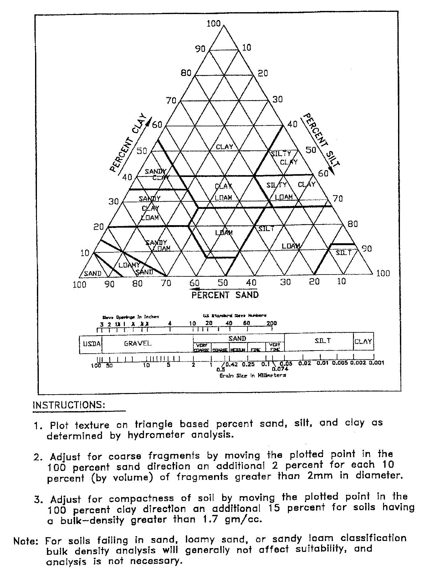
(3) Soils classified as sandy loam, sandy clay loam, and loam may be considered suitable for effluent disposal without additional percolation testing provided that the texture is confirmed using a hydrometer test. If an alternative system is necessary, percolation testing under fully saturated conditions may be required to determine design parameters. If multiple soil profiles are evaluated, then only one soil sample needs to be analyzed using a hydrometer test, provided the soil sample is taken from the most limiting soil layer observed from all soil profiles evaluated. All samples shall be appropriately labeled, and analyzed for soil texture and bulk density by the approved ASTM method or California Test Method. The tests shall demonstrate the presence of the minimum effective soil depth required beneath the trench or absorption bed. The test results shall be plotted on a soils textural triangle as shown in Figure 1.
(4) Soils classified as sandy clay, clay loam, silt loam, silty clay, silty clay loam, silt, and clay shall be considered marginal to unacceptable and will require percolation testing to determine whether the soils are suitable.
(5) If the classification of the soil is in question, then the Environmental Health Services Division shall require the consultant to provide hydrometer and bulk density test data to verify the actual classification of the soil on the soils textural triangle in Figure 1 to determine if percolation testing is required.
(d) Percolation testing.
Figure 1: USDA Soil Textural Triangle
(1) When required by these standards to demonstrate adequate infiltrative capacity at a proposed on-site sewage disposal system location, percolation testing shall be performed or supervised by a registered consultant in compliance with Solano County’s approved percolation test procedures. The applicant shall notify the Environmental Health Services Division at least 24 hours prior to constructing percolation test holes, presoaking the test holes, and conducting the test.
Percolation test holes shall be constructed during normal business hours unless prior arrangements have been made with the Environmental Health Services Division. The Environmental Health Services Division may require inspection of the percolation test hole construction process and/or presoak method, and percolation test. Failure to comply with these requirements may result in the need to reconstruct the test holes, and/or conduct a new presoak, and/or perform a new percolation test. All applicable fees shall be paid prior to construction of the percolation test holes.
(2) When deemed necessary by the Environmental Health Services Division, percolation tests may be required for any on-site sewage disposal permit application involving new construction, increases in the projected wastewater flow, relocation or expansion of an existing systems, and for land divisions or lot line adjustments, which do, or will, use on-site sewage disposal systems. The Environmental Health Services Division may require percolation tests prior to the issuance of permits to repair failing on-site sewage disposal systems, or prior to approving building additions on lots served by on-site sewage disposal systems.
(3) Percolation Test Hole Construction
(A) Percolation test holes shall be placed uniformly into the undisturbed soil horizons in the proposed location of the initial and replacement on-site sewage disposal system’s absorption field. At least three holes shall be placed in each proposed disposal field and in each reserve area location. Test holes shall be constructed to the depth of the bottom of the proposed leachfield. For Mounds and At-Grade Mounds, the depth of the leachfield for purposes of test hole depth, shall be considered 1 foot below grade. The registered consultant may construct one or more percolation holes at the midpoint elevation of the minimum effective soil depth for the purpose of application rate determination in conformance with section 6.4-87.2. For tests deeper than one foot a backhoe may be used to dig a bench to within one foot of the bottom of the test hole, provided the backhoe pit is left open. The registered consultant running the test is responsible for any needed shoring in deeper tests.
(B) Percolation test holes shall be at least four (4") inches to twelve (12") inches in diameter. The bottom and sides of the percolation test holes shall be carefully scratched with a sharp instrument to remove any smeared soil surfaces and provide a natural soil interface into which water may percolate. All loose soil must be removed from the hole.
(C) Not more than two (2") inches of coarse sand or pea gravel must be placed in the bottom of the hole to protect from scouring and sediment that may impact the test.
(D) The hole shall be left open, or a minimum four (4") inch perforated pipe with approved drain rock between the pipe and wall of the hole shall be placed in the test holes. The backhoe pit, if used for deep percolation tests, shall remain open and unfilled.
(4) Presoaking the Test Holes
The intent of this section is to provide sufficient presoaking that will result in soil conditions that represent, as closely as possible, those conditions encountered during the wettest months of the year.
(A) Standard Procedure.
Each percolation test hole shall be presoaked for a minimum of six (6) hours prior to the start of the percolation test or until the soils are completely swollen, whichever is longer. The six hour presoak shall not begin more than 24 hours prior to the start of the test. The Registered Consultant shall consider the soil texture and type in selecting an appropriate presoak period.-Underestimating the presoak time period will result in an extended rate measurement period. Many soils in Solano County will require a presoaking time period greater than six (6) hours. The Environmental Health Services Division may approve a shorter presoak period for soils with textures of sand, loamy sand or sandy loam.
(B) Presoak procedures shall result in complete wetting and swelling of the soil being tested. This shall be accomplished by thoroughly saturating each hole until the soil is fully swollen (this may require many gallons of water).
The water level in the percolation hole shall be maintained at least 12" above the sand or pea gravel at the bottom of the hole as required for the soil to achieve a swollen condition prior to the start of the percolation rate measurement. Only clean water without additives shall be used in the presoak and percolation tests.
(C) Failure to follow the presoak procedures may result in the requirement to begin the presoak procedure again, or lack of approval of the percolation test results.
(5) Percolation Rate Measurement
The intent of this section is to provide precise and accurate percolation rate measurements, of sufficient time, that represent to the greatest extent possible, the soil conditions encountered during the wettest months of the year.
(A) At the beginning of the percolation test, the depth of the percolation hole shall be recorded and the water shall be adjusted so that it is between 4 and 8 inches above the sand or pea gravel at the bottom of the hole.
(B) A fixed reference point over the hole, or on the side of the perforated pipe if used, must be established. All readings shall be taken from this fixed reference point to the top of the water in the hole. Floats with securely attached measuring devices may be utilized provided that the floats do not absorb water. The distance between the water and ground surface shall be recorded.
(C) Water level shall be measured to a minimum accuracy of one-eighth (1/8") inch every thirty (30) minutes for a minimum of four (4) hours and until three (3) consecutive stabilized measurements are made that are within 1/4th inch of the final measurement. If water cannot be maintained in the hole for the first two (2) thirty (30) minute readings, then the water level shall be adjusted to six (6") inches over the sand or pea gravel at the bottom of the hole, and readings shall be taken every ten (10) minutes for two (2) hours or until three (3) consecutive stabilized measurements are made, whichever is longer.
(D) For test holes with a permeability faster than 30 mpi after the required test period that do not have rates for a final three readings that are within 1/4" of the last reading, an average of the last three readings will be used as the percolation rate.
(E) Inadequate presoaking of the test holes may result in unstabilized percolation rates at the end of a percolation test. In no case shall the percolation test end until the minimum percolation rate period has been reached and a stabilized rate has been achieved, as defined in section 6.4-81.2(d)(6)(c), unless the consultant chooses to repeat the test. Percolation test data that does not achieve a stabilized rate shall not be utilized in the design of sewage disposal systems.
(6) Percolation Test Data
(A) All data obtained from any percolation test shall be included in the site evaluation report submitted to the Environmental Health Services Division on the standard form provided. All test results, both passing and failing, shall be submitted.
(B) The completed report shall be accompanied by a scaled plot plan identifying the exact location of the percolation holes, along with other pertinent details such as the location of soil profiles, wells, water courses, structures, slopes, cut banks, property lines, etc.
(C) All data submitted must be stamped and signed by the registered consultant supervising or performing the tests.
(D) Groundwater determination.
(1) The highest anticipated level of groundwater shall be estimated by the highest extent of soil mottling to natural grade observed in a soil profile, or by direct observation of stabilized groundwater levels.
(2) Direct observations, if used or required, shall occur during wet weather conditions as defined below. Measurements shall occur every 2 weeks during the wet weather period. The Environmental Health Services Division may accept alternate wet weather groundwater plans from registered consultants provided the groundwater monitoring plan will capture seasonal high groundwater elevation in the proposed primary and reserve disposal fields. Direct observation of groundwater shall utilize performance wells or piezometers. At least one well shall be constructed in each initial and replacement area. Approval of the monitoring program shall be obtained from the Environmental Health Services Division. The location of the well(s) shall be accurately depicted on all site plans submitted to the Environmental Health Services Division for approval of the on-site sewage disposal system. Where a conflict exists between the depth of groundwater observed through direct observation during wet weather conditions and the depth at which soil mottles are observed, the direct observation of actual groundwater levels shall govern.
(3) Some soils, such as sandy river soils, will not exhibit mottling. In cases where the soil lacks the necessary iron compounds to exhibit mottling, direct observation during wet weather conditions may be exclusively required.
(e) Wet weather testing period.
(1) The wet weather testing period for groundwater determination and, where required, for wet-weather percolation testing shall be determined annually by the Environmental Health Services Division on the basis of rainfall occurrence as measured by the following schedule:
(A) Beginning: On the occurrence of fifty (50%) percent of the annual normal rainfall or after 8 inches of rainfall in any 30 day period, whichever occurs first.
(B) Ending: On March 15, or later as determined by the Environmental Health Services Division in the event of unusually heavy springtime rainfall.
(C) Extensions: The wet weather testing period may be started earlier or extended later than the above-noted beginning and ending points if it is determined by the Environmental Health Services Division, through a monitoring program, that shallow groundwater tables are fully charged.
(f) Soil test results completed pursuant to these standards shall be valid as long as the conditions on the lot remain essentially unaltered by grading, construction, drainage, structures, well, cuts, landslides, etc. Testing may be invalidated if subsequent site evaluations reveal site conditions that are more limiting than noted during original tests, or that were misrepresented or ignored during original testing.
(g) Nothing in this Chapter shall prohibit a registered consultant from conducting percolation testing in accordance with these standards prior to soil profile evaluation.
(Ord. No. 1609, §18; Ord. No. 1655, §16)
6.4-82 Disposal system location and placement
(a) Soil depth.
(1) On-site sewage disposal systems shall be placed within and above effective soil. The effective soil depth below the bottom of the disposal field shall be as indicated in Table 1.
(2) Soil Texture Zones are those described in Figure 1, USDA Soil Textural Triangle. Increased depth of permeable soil may be required for systems proposed on sloping terrain. All horizons of the soil must comply with criteria established by these standards in order to be considered effective soil.
(b) Percentage of Rock. The percentage of coarse fragments throughout the effective soil depth shall not exceed fifty (50%) percent by volume as retained on a #10 sieve.
(c) Percolation Rates. The disposal field shall not be placed in an area with failing percolation test results. Percolation test results throughout the disposal field area and required effective soil depth shall not be less than one minute per inch or more than 60 minutes per inch. Exception: for alternative and experimental sewage disposal systems the percolation test results throughout the disposal field area and required effective soil depth shall not be less than one minute per inch or more than 120 minutes per inch.
(d) Slope. The native slope of any portion of a standard disposal field area shall not exceed twenty five (25%) percent. Other slope limitations may apply depending on the type of on-site sewage disposal system proposed. Lots may not be graded or altered in any manner to accommodate the slope requirements (except as indicated for areas of fill in section 6.4-82(e) below). Leach lines shall not be installed in areas of excessively concave slopes.
(e) Areas of filled soil or unstable soil formations shall not be used for a disposal field site. The on-site sewage disposal system shall be located and installed in natural, undisturbed and unobstructed ground or earth. Exception: fill placed for ten or more years that are stable and soil evaluation indicates characteristics acceptable for installation of an on-site sewage disposal system such as approved structure, texture, consistency, pore space, percolation rate, etc., may be utilized for an on-site sewage disposal system. No grading shall occur in the area of the proposed or installed on-site sewage disposal system or replacement area without the written approval of the Environmental Health Services Division.
(f) The minimum horizontal separation between the components of the system, including the required reserve area, and the subjects listed below shall be as shown in Table 2: Minimum Setback Requirements.
Where adverse conditions exist, the minimum horizontal separation distances specified by this section may be increased or a special means, particularly in the construction of the on-site sewage disposal system, may be required by the Environmental Health Services Division.
|
Soil texture1 |
Percolation Rate |
Depth to groundwater |
Depth to other limiting factor |
|---|---|---|---|
|
Sand, Loamy Sand |
1 mpi - 5 mpi 6 mpi- 60 mpi |
20 feet2 5 feet3 |
5 feet3 5 feet3 |
|
Sandy Loam, Sandy Clay Loam, Loam |
6 mpi - 60 mpi 61 mpi- 120mpi |
5 feet3 3 feet4 |
5 feet3 3 feet4 |
|
Sandy Clay,Clay Loam, Clay, Silty Clay, Silty Clay Loam, Silt Loam, Silt |
6 mpi - 60 mpi 61 mpi- 120mpi |
5 feet3 3 feet4 |
5 feet3 3 feet4 |
1. Soil texture of most limiting soil layer in the active leaching layers directly below proposed disposal fields (within two (2') feet to five (5') feet below trench bottom depending on type of system).
2. Unless an alternative system is utilized, then depth may be reduced to two (2') feet to five (5') dependent on the alternative system proposed. Pretreatment and denitrification may be required for any allowed reduction of setback.
3. Separation distances may be reduced to three (3') feet if pressure distribution is used, or to two (2') feet if a pretreatment device approved by the Environmental Health Services Division is used prior to disposal of effluent into the soil through pressure distribution.
4. Applies only to sites approved for alternative sewage disposal systems utilizing pressure distribution methods. Can be reduced to two (2') feet if a pretreatment device approved by the Environmental Health Services Division is used prior to disposal of effluent into the soil.
|
|
Septic Tank, Interceptor, Dosing Tank, Holding Tank, Distribution Box |
Disposal Field, Replacement Area |
Solid Piping (ABS or Cast Iron) |
Solid Piping (PVC or other) |
|---|---|---|---|---|
|
Wells, abandoned wells, springs |
100 feet(1) |
100 feet |
25 feet |
50 feet |
|
Bays, streams, rivers, ditches, canals, culverts or 10 year flood plains (2) |
100 feet(1) |
100 feet |
25 feet(3) |
50 feet |
|
Ephemeral streams, rivers, unlined ditches, unlined canals, or unlined culverts (2) |
50 feet |
50 feet |
25 feet(3) |
50 feet |
|
Lined ditches, lined canals, or watertight culverts or conduits |
15 feet |
15 feet |
10 feet(3) |
10 feet |
|
Lake or reservoir (2) |
100 feet |
100 feet |
25 feet |
50 feet |
|
Property line (public water supply and no on-site well) |
10 feet |
10 feet |
10 feet |
10 feet |
|
Property line (neighboring lot on-site well or spring water supply) |
25 feet |
25 feet |
10 feet |
10 feet |
|
Structures and foundations |
5 feet |
10 feet |
0 feet |
5 feet |
|
Swimming Pool. Lined pond or lined basin |
15 feet |
15 feet |
5 feet |
5 feet |
|
Areas subject to vehicular traffic |
5 feet |
5 feet |
0 feet if sand packed |
5 feet |
|
Cut or fill banks, cuts, or steep slopes(4) |
4 x height (50 feet maximum) |
4 x height (100 feet maximum) |
0 feet |
10 feet |
|
Easements and rights of way (5) |
5 feet |
5 feet |
5 feet |
5 feet |
Notes:
(1) May be reduced to fifty (50') feet if the tank passes a field test to verify it is water tight.
(2) As measured from the highest water level obtained.
(3) Variance may be granted for creek crossings if pipe is pressure tested and adequately protected.
(4) Distance in feet equals four times the vertical height of the cut bank, fill bank, or escarpment.
(5) Unless easement is specifically and solely designated for an on-site sewage disposal system.
See Uniform Plumbing Code for parallel crossings.
(Ord. No. 1609, §18; Ord. No. 6155, §17)
6.4-83 Intercept drains
(a) Intercept drains are trenches filled with gravel and drainage pipe installed below ground up slope from the disposal field for the purpose of intercepting, diverting, and discharging perched groundwater away from the disposal field. The goal is to eliminate completely, or significantly lower, the perched groundwater in the area of the disposal field to accommodate a specific design of on-site sewage disposal system.
(b) Intercept drains may be used to eliminate or lower perched water tables to allow a site to be used for sewage disposal when all of the following criteria can be met:
(1) The native slope exceeds 5%.
(2) The water table is shallow and perched on an impermeable subsurface feature such as bedrock, hardpan, or impermeable clay.
(3) The bottom of the intercept drain can be keyed into the impermeable feature.
(4) Monitoring to verify that the intercept drain is lowering the groundwater to approved levels shall be required. Performance wells shall be installed between the intercept drain and the absorption field to verify groundwater levels. The owner of the property shall be responsible for paying fees associated with ongoing monitoring and evaluation. The Environmental Health Services Division shall condition the on-site sewage disposal system permit with the provisions for monitoring.
(c) No portion of an intercept drain shall be located less than 10 feet up gradient, 15 feet laterally, or less than 50 feet down gradient from any septic tank or disposal field, replacement area, or less than 5 feet from any property line. Detailed plans prepared by a registered geologist, registered civil engineer or registered environmental health specialist must be submitted to and approved by the Environmental Health Services Division prior to installation of an intercept drain.
(Ord. No. 1609, §18; Ord. No. 1655, §18)
6.4-84 Materials
(a) Materials used in construction of the septic system shall be in good condition, durable, sound, free from defects, capable of withstanding normal installation and operational stresses, and resistant to corrosion or decay.
(b) All materials, fixtures, pipe, fittings, distribution boxes, and devices used to construct a septic system must be IAPMO approved and listed, or be approved by the Environmental Health Services Division for the use intended. Approval by the Environmental Health Services Division may only be given after submission of detailed engineered designs that demonstrate compliance with all applicable standards.
(Ord. No. 1609, §18)
6.4-84.1 Septic tank, dosing tank, and interceptor construction, inspection, testing, and capacity
(a) Each septic tank, dosing tank, and interceptor shall be designed, installed and maintained so as to prevent the entrance of rain, groundwater, or surface water drainage.
(b) All septic tanks, dosing tanks, interceptors, distribution boxes, risers, seams, joints and unions shall be made watertight. The Environmental Health Services Division may require a leak test in the field to confirm water tightness. When a leak test is required, water shall be placed two inches above the seam of the tank and riser. The water level must remain static within one (1") inch for a twenty four-hour period.
(c) Minimum septic tank capacity for single family residences shall be as follows:
|
Residences with 1 to 3 bedrooms: |
1200 gallons |
|
Residences with 4 bedrooms: |
1500 gallons |
|
Residences with 5 bedrooms: |
1800 gallons |
|
Each additional bedroom: |
150 gallons |
|
|
|
|
Commercial establishments (including residential care facilities) |
|
|
Vol.= 1.5 Q + 1000 where Q’ maximum daily flow. |
|
(d) Approved Septic Tanks: Septic tanks shall be designed to provide clarified effluent consistent with accepted standards and shall provide adequate space for sludge and scum accumulations. Designs shall assure uniform flow through the entire length of the septic tank. The interior of all concrete tanks, above the liquid level, shall be coated with a bituminous coating or other approved material to prevent the degradation of concrete by sewage gases. The tank shall be permanently marked with the capacity and manufacturer and be accessible for cleaning and inspection.
(e) Compartments: The septic tanks shall be of two-compartment construction. The first compartment shall be twice the capacity of the second compartment and be separated from the second compartment by a baffle. The first compartment shall be at least three feet wide and five feet long with a liquid depth between 2 1/2 feet and six feet. In septic tanks greater than 1500 gallons the second compartment may not be less than five feet in length. Side walls of the septic tank shall extend at least nine (9") inches above the liquid level. The baffle shall extend at least four (4") inches above the liquid level. A four (4") inch inverted fitting with the opening extending midway into the liquid level of the septic tank shall be installed in the inlet compartment side of the baffle.
(f) The invert of the inlet opening into the septic tank shall be at least two (2") inches above the invert of the outlet opening. The inlet and outlet pipe openings shall not be less in size then the connecting sewer pipe. The inlet and outlet pipes shall be provided with sanitary tees of equal internal diameter. The portion of the sanitary tee on the outlet extending into and above the liquid level may be larger than the outlet pipe to accommodate an effluent filter. Sanitary tees shall extend at least four (4") inches above and twelve (12") inches below the liquid level of the tank. Sanitary tees shall be located under the access openings. Ventilation shall be provided through the sanitary tees by means of a two-inch minimum space between the underside of the septic tank top and the top of the sanitary tee fitting. All pipe fitting and compartment partitions shall have a free vent area equal to or larger than the required cross sectional area of the house sewer discharging into the tank to provide free ventilation above the liquid level from the disposal field to the septic tank, house sewer and stack into the air.
(g) The top of the tank shall be located no greater than thirty-six (36") inches below grade unless otherwise approved in writing by the Environmental Health Services Division.
(h) Access to each compartment of a tank shall be provided by an access opening twenty (20") inches in minimum dimension into the top of the tank. A riser shall extend to two (2") inches above grade from each access opening of the tank to allow for inspection and maintenance of the tank. The risers shall be centered over the access openings into the tank. The riser shall be of sufficient size to protect access openings of the tank and allow for removal of any below grade covers if present. Watertight, airtight, vermin tight, securely fastened covers shall be installed over the risers. The covers must be removable with standard hand held tools. Risers and covers shall be constructed of durable materials approved by the Environmental Health Services Division. The riser shall be fastened to the septic tank with a durable, watertight seal that is either cast in place or retrofitted. The risers and lids shall be specifically manufactured for the use intended and shall be capable of withstanding all anticipated loads. Wherever the first compartment exceeds twelve (12') feet in length, an additional access opening with riser shall be provided over the baffle wall.
(i) Construction Materials. Unless otherwise approved in writing by the Environmental Health Services Division, septic tanks shall be constructed of reinforced concrete. Fiberglass or polyethylene tanks may be permitted only in circumstances where the placement of a concrete tank is not feasible because of access limitations, steep slopes, safety concerns or remote sites unless written approval is obtained from the Environmental Health Services Division. Fiberglass or polyethylene tanks are prohibited in areas of shallow groundwater where buoyancy is a concern. When fiberglass or polyethylene tanks are used, they must be installed and bedded in strict conformance with the manufacturer’s instructions.
(j) Structural and Material Strength. The tank shall be capable of withstanding anticipated structural loads. The tank top must be capable of supporting an earth load of not less than three hundred (300 lbs) pounds per square foot when maximum coverage does not exceed three (3') feet. The minimum compressive strength of any concrete tank wall, top and covers, or floor is two thousand five hundred (2500 lbs) pounds per square inch.
(k) Installation: Concrete tanks shall be installed level and on a solid bed of at least 90% compacted earth or rock. Soil around the tank shall be hard-compacted or jetted. The depth of tank placement and additional installation details shall be as specified in the approved on-site sewage disposal system permit. Each of the following components of an on-site sewage disposal system shall be located at least two (2') feet from each other and five (5') feet from a distribution box and/or an absorption field as measured horizontally:
(1) Grease interceptor
(2) Septic tank
(3) Dosing tank
(l) When installed in locations where the seasonal groundwater is less than six (6') feet from the ground surface, tanks shall be made non-buoyant by the addition of concrete to the bottom or top surface of the tank, or by other means approved by the Environmental Health Services Division.
(m) The Environmental Health Services Division shall conduct inspection of the tank at the time of installation. Tanks that are cracked, caved, or structurally deficient shall not be approved.
(n) An effluent filter approved by the Environmental Health Services Division shall be required in the outlet of all newly installed septic tanks, except if a dosing tank with a screened pump vault is being used immediately after the septic tank.
(o) Grease Interceptors
(1) Wastewater discharge from fixtures and equipment in commercial establishments which may contain grease, including but not limited to scullery sinks, pot and pan sinks, dishwashing machines, soup kettles and floor drains located in areas of food preparation shall only be drained to an on-site sewage disposal system through a grease interceptor.
(2) Any commercial food establishments using an on-site sewage disposal system except those serving drinks and/or prepackaged food only, shall have an interceptor installed pursuant to the provisions of these regulations prior to any transfer of operating permit by the Environmental Health Services Division.
(3) General Grease Interceptor Requirements
(A) Toilets, urinals, and other similar fixtures shall not discharge through an interceptor.
(B) An interceptor shall be identical to a septic tank designed pursuant to the provisions of these regulations except that the sanitary tees shall extend to a level of 12 inches from the bottom of the tank and an effluent filter is not required.
(C) All interceptors shall have risers provided over each access port as indicated in section 6.4-84.1(h).
(D) The interceptors shall be located outside of the structure and as close as possible to the source of grease. The location shall allow for ease of access for removal of the interceptor’s contents.
(E) Interceptors shall discharge to a septic tank or sewer.
(F) Interceptors shall be at least 1000 gallons or sized based upon the following formulas below, whichever is greater:
(i) Commercial Kitchen:
Capacity = Number of meals per hour multiplied by the waste flow rate multiplied by retention time multiplied by storage factor.
(ii) Laundries and laundromats:
Capacity = number of machines multiplied by 2 cycles per hour multiplied by waste flow rate multiplied by retention time multiplied by storage factor.
(G) Retention times and storage factors shall be equal to or greater than those listed in Table 3 or as determined by the Environmental Health Services Division if not listed. Waste flow rates are those listed in Table 4 or as determined by the Environmental Health Services Division if not listed.
(p) Distribution box specifications
(1) Distribution boxes shall be watertight and designed to accommodate the necessary distribution laterals and expected flows.
(2) Distribution boxes shall be constructed of durable, non-porous materials such as Class “A” concrete or other materials approved by the Environmental Health Services Division. The top, walls, and bottom of concrete distribution boxes shall be at least two (2") inches thick.
|
FACILITY |
RETENTION TIME |
STORAGE FACTOR |
|---|---|---|
|
Commercial Kitchen |
Dishwasher and/or disposal unit = 2.5 hours. Single serving with disposal = 1.5 hours |
Fully equipped kitchen: 8 hour operation = 1 16 hour operation = 2 24 hour operation = 3 Single service kitchen = 1.5 |
|
Laundry |
2.0 hours |
1.5 |
(3) Distribution boxes shall be constructed with a baffle or similar design.
(4) The inside of concrete distribution boxes shall be coated with a bituminous or other approved coating above the level of the sewage effluent.
(5) The invert of the inlet pipe shall be at least one (1") inch higher than the invert of the outlet pipes. The inverts of all outlet pipes shall be level.
(Ord. No. 1609, §18; Ord. No. 1655, §19)
6.4-84.2 Pump systems
(a) A licensed Civil Engineer, Certified Engineering Geologist or a Registered Environmental Health Specialist shall design all pump systems. Plans detailing the dosing tank, pump, and all component features, including a cross section of the tank complete with elevations of control switches, measured in inches, from the bottom of the chamber must be provided to the Environmental Health Services Division for review. Dosing tanks shall only receive clarified effluent that has been treated by a septic tank or pretreatment device.
(b) Dosing tank design is to include the following:
(1) Emergency storage volume shall be 150 gallons or 1/3 of the design flow rate, whichever is greater and is measured from the invert of the inlet tee and the point of high water alarm activation.
(2) In order to prevent floatation in areas where ground water will come into contact with the dosing tank the design must account for the volume of effluent required to remain in the tank after dosing occurs, or anti-flotation devices must be used.
(3) The access opening(s) into the top of the dosing tank and risers shall comply with section 6.4-84.1(h) and shall be designed and sized to allow ease of maintenance and removal of the pump, pump vault, screens, floats, and other components that may be within the dosing tank.
(4) Dosing tanks shall be vented back through the septic tank, or have a separate vent.
(5) A check valve shall be required unless the leach field or absorption system is located downhill from the pump.
(c) Requirements pertaining to the pump and associated controls are as follow:
(1) The pump off switch shall be set per manufacturer’s specifications. A redundant “off” switch shall be used.
(2) The pump shall be placed so that it remains submerged to allow for cooling and prevent contact with sewer gas. The pump shall be set a minimum of four (4") inches above the bottom of the dosing tank.
(3) Float control switches shall be set to pump small, frequent doses. Timed dosages may be utilized in addition to on/off switches. The use of a dosing timer may be required in order not to exceed maximum allowable dosages for the specific on-site sewage disposal system proposed.
(4) The pump in the dosing tank shall be protected by either an effluent filter located in the septic tank, or by placement within a screened vault located in the dosing tank, or both.
(5) The pump shall be designed for sewage effluent and shall be U.L. approved. Pump curves and other required test certification shall be submitted to the Environmental Health Services Division for approval.
(6) The alarm system is to contain an audible and visual alarm that will remain on once activated until turned off by the owner or maintenance person. The alarm must be installed on a separate circuit from the pump.
(7) The high water alarm switch shall be set two inches above the pump “on” switch.
(8) Alternating pumps are required for systems generating over 1500 gallons per day, or for commercial systems.
(9) A single family dwelling may use duplex pumps or a single pump. For using a single pump, the following criteria shall be used:
(A) The single pump is to be commercially engineered and capable of continuous duty.
(B) The pump must be capable of handling the total design flow of the on-site sewage disposal system.
(10) The control panel shall have a method to count the number of doses and elapsed time the pump is running.
(d) Requirements for the force main are:
(1) The force main is to be from one and one-quarter (1 1/4") to two (2") inches in diameter, rated for the head loss calculated pressure and velocity, and made of approved materials.
(2) The connection between the pumps and the force main shall allow for ease of pump removal and maintenance.
(3) Head loss calculations addressing all fittings and elevation differences must be provided with plan submittal to the Environmental Health Services Division.
(e) Exception: a separate dosing tank shall not be required if both of the following conditions are met:
(1) The pump system is being installed to repair an existing failed or failing on-site sewage disposal system, and the installation of a dosing tank is not possible or practical given site conditions, and
(2) If possible the pump shall be placed in a pump vault separate from the septic tank. However, if the pump is proposed to be placed in the septic tank for repair to a failed or failing on-site sewage disposal system, then the following criteria must be met:
(A) The pump flow rate and dose batch size shall be kept to a minimum to prevent surging of liquid levels in the septic tank.
(B) The pump shall be placed in the second compartment within a screened pump vault.
(C) The pump intake shall be equal distance between the liquid operating level and the bottom of the septic tank.
(D) The pump “off” switch must be set four (4") inches above the crossover pipe within the baffle to prevent first compartment scum from entering the second compartment.
(Ord. No. 1609, §18; Ord. No. 1655, §20, §21)
6.4-85 Destruction of tanks
(a) Every cesspool, septic tank, interceptor, dosing tank, holding tank, or pit privy which has been abandoned, or has been discontinued from further use, or to which no building drain or building sewer from a plumbing fixture is connected, shall be immediately destroyed by filling with compact earth, sand, gravel, concrete or other material approved by the Environmental Health Services Division. Prior to filling, the top cover or arch over the cesspool, interceptor, septic tank, dosing tank, holding tank or pit privy shall be completely removed, the wastewater removed by an approved septage hauler, and at least five holes shall be broken into the bottom. Fill material shall not be placed above the top of the sidewalls, or above the level of any outlet pipe, until inspection and approval by the Environmental Health Services Division. After approval by the Environmental Health Services Division, the cesspool, septic tank, dosing tank, holding tank or pit privy shall be filled at least to grade level. An adequate fill cap shall be provided to account for future settling. Complete removal of the tank and backfill and compaction of the hole after its removal, is an acceptable alternative to destruction of the septic tank in place.
(b) Where on-site sewage disposal systems are abandoned after connecting any premises to a sanitary sewer, all abandoned on-site sewage disposal systems shall be destroyed within 30 days of the time of connecting to the sanitary sewer.
(Ord. No. 1609, §18; Ord. No. 1655, §22)
6.4-86 Piping, joints, and connections
(a) All piping, joints and connections shall: (1) be at least three (3") inches internal diameter except as otherwise specified by the Environmental Health Services Division for piping subject to pressure; (2) have watertight joints; (3) be laid on stabilized, compacted earth, except for perforated piping within disposal area; (4) be installed pursuant to the requirements of these standards and IAPMO and the manufacturer’s specifications; (5) be backfilled by soil free of large rocks and debris that may damage the piping, joints, and/or connections; (6) shall meet the minimum requirements of the Uniform Plumbing Code; and (7) shall be marked by an approved listing agency.
(b) Pipe under driveways or other areas subject to heavy loads shall be installed to withstand the imposed loads.
(c) The Environmental Health Services Division may require the use of tracer wire for the location of piping systems.
(d) The building sewer shall have no tight ells or bends of 90 degrees.
(e) Cleanouts
(1) Cleanouts extending to grade shall be provided between the structure served by an on-site sewage disposal system and any septic tank or interceptor every 100 feet, or fraction thereof, of straight runs of building sewer and for each bend less than 1350 between pipes.
(2) All cleanouts shall extend to grade and shall be installed so as to allow cleaning in both directions.
(3) Cleanouts installed under concrete or asphalt paving shall be made accessible through risers or by extending flush with paving and shall be adequately protected.
(f) All piping, joints, and connections shall be ABS or cast iron, except for pipe subject to pressure and perforated pipe in the disposal field, which may be PVC.
(g) The fall between the structure and the septic tank or aerobic treatment unit if not preceded by a septic tank shall be at least one-quarter (1/4") inch per foot. Between the septic tank and the distribution box the fall shall be at least one (1") inch in ten (10') feet.
(Ord. No. 1609, §18; Ord. No. 1655, §23)
6.4-87 Absorption system: infiltration area and sizing the system
(a) Typical Standard Leach Field Design
(1) The typical standard leach field design for an on-site sewage disposal system may be used under the following conditions:
(A) There is gravity flow from the septic tank to all other portions of the on-site sewage disposal system.
(B) Soil evaluation has shown that:
(i) Groundwater, fractured rock, hardpan, bedrock, or other limiting condition is not encountered from natural ground surface to five (5') feet below the proposed trench bottom, and
(ii) The soil from ground surface to five (5') feet below trench bottom is classified as a sandy loam, sandy clay loam, or loam or, if classified as a sand, loamy sand, clay loam, sandy clay, or silt loam has a percolation rate from 6 to 60 mpi, and
(iii) The soil is not classified as a clay, silty clay, silty clay loam, or silt.
(C) The system serves a residential dwelling with four (4) bedrooms or less and the wastewater generated does not exceed six hundred (600) gallons per day.
(2) The typical standard leach field design shall be: six hundred (600') lineal feet of trench, not more than thirty-six (36") inches deep by thirty-six (36") inches wide; a three (3") inch minimum diameter perforated pipe shall run the entire length of each trench; twelve (12") to eighteen (18") inches of gravel under the pipe and two (2") inches of gravel over the pipe shall be installed. Chamber systems that provide equivalent treatment may be substituted for the gravel trenches. No reduction in length of the total lineal feet required will be allowed for the use of a chamber system. Gravel trenches and chamber systems shall have twelve to eighteen inches of cover soil. The top of the gravel layer or chamber may be installed as high as flush with grade.
(b) Non-Typical Standard Leach Field Design and Alternative Systems.
For systems that do not meet the requirements for a typical standard leach field design, or if the owner decides to pursue a non-typical standard design or alternative system design on a site where a typical standard design would normally be allowed, then a Registered Civil Engineer, Certified Engineering Geologist or Registered Environmental Health Specialist shall prepare and design an on-site sewage disposal system complying to these standards for the proposed building. Any design shall incorporate the following criteria:
(1) The total length of leach line required shall be calculated using the infiltrative area as specified in this section. For calculation purposes the infiltrative area per lineal foot shall not exceed 3 square feet per lineal foot unless the effective soil below the leachfield consists of loam, sandy loam or sandy clay loam in which case the maximum infiltrative surface area shall not exceed 5 square feet per lineal foot. For systems utilizing more than 3 square feet per lineal foot, only side wall shall be used in the calculation of infiltrative surface area. The infiltrative area used to calculate the size of absorption beds or trenches for alternative systems shall not exceed the specifications established by these standards for the specific type of disposal system proposed.
(2) Projected wastewater flows. On-site sewage disposal system designs shall be determined based upon site evaluation and the determination of the projected maximum daily flow. The minimum design capacity of any on-site sewage disposal system designed by a licensed consultant serving new construction of a residential structure or project shall not be less than 450 gallons per day. Projected wastewater flow for single family dwelling units with more than three bedrooms shall be increased by 150 gallons per day for each additional bedroom. (Exception: Legal second dwelling units with a separate septic system shall have a minimum design capacity of not less than 150 gallons per day per bedroom.) For repairs or additions to on-site sewage disposal systems for residential occupancies the sewage flow shall be based on 150 gallons per bedroom per day. For other types of occupancies, the projected sewage flow shall be based upon 150 gallons per day, or Table 4, or if not listed in Table 4, as approved by the Environmental Health Services Division, whichever is greater. For multiple residences, establishments, or occupancies in the same.
|
TYPE OF OCCUPANCY |
GALLONS PER DAY |
|---|---|
|
Airports |
5 per passenger |
|
Campgrounds: |
|
|
Campground with central comfort station |
35 per person |
|
Campground with flush toilets, no showers |
25 per person |
|
Day Camps (no meals served) |
15 per person |
|
Summer and seasonal |
50 per person |
|
Churches (sanctuary) |
5 per seat |
|
With kitchen wastes |
7 per seat |
|
Factories |
35 per person per shift |
|
Hospitals |
250 per bed space |
|
Kitchen waste only |
25 per bed |
|
Laundry waste only |
40 per bed |
|
Hotels/Motels with private bathroom (No kitchen waste) |
60 per two person room |
|
Hotels/Motels without private bathroom (No kitchen waste) |
50 per two person room |
|
Hotels/Motels with private bathroom and kitchen |
75 gallons per person |
|
Institutions other than hospitals |
125 per bed space |
|
Movie Theaters |
5 per seat |
|
Offices |
20 per employee |
|
Picnic Parks with toilets and showers |
10 per person |
|
Picnic parks with toilet waste only |
5 gallons per person |
|
Resort Camps with limited plumbing |
50 gallons per person |
|
Restaurants: Kitchen wastes (multi use utensil) |
5 per meal served |
|
Kitchen wastes disposable utensil |
3 per meal served |
|
And add the following for type of facility present: |
|
|
Conventional sit down |
10 per person |
|
Short Order |
8 per person |
|
Bar and Cocktail |
3 per person |
|
Schools (non-boarding) |
20 per student |
|
With gym and showers add |
5 per student |
|
With cafeteria using disposable utensils |
3 per meal served |
|
Self service laundries |
50 gallons per wash |
|
Service Stations |
10 gallons per vehicle served |
|
Retail Stores |
20 per employee |
|
For public restroom add |
1 per 10 square feet |
|
Swimming pools and bathhouses |
10 per person |
|
Tourist camps or mobile home parks with individual bath units |
100 per person |
|
Tourist camps or trailer parks with central bathhouse |
75 per person |
|
Work or construction camps (semi-permanent) |
50 per person |
|
Wine Tasting Facility (no meals served) |
3 per person |
Note: Employee use shall be added to all above occupancies at a volume of 20 gallons per day per employee establishment, the cumulative projected wastewater flow as determined by the Environmental Health Services Division shall be used.
For intermittently used on-site sewage disposal systems, the design capacity shall be based on the maximum projected daily flow during the period of use. Waste flow values that incorporate periods of non-use shall not be used in the design. Seating or occupant capacity of any establishment shall be based on the maximum occupancy permitted by the local fire marshal.
(B) The on-site sewage disposal system’s disposal field shall be sized according to the infiltration rates listed in Table 5 or Table 6. The table used shall be based on the final test method utilized to determine infiltration rate.
(C) Hydrometer test and percolation rates.
If percolation tests are required, then typical and non-typical standard disposal fields may be used only if percolation test results are between 6 mpi and 60 mpi, inclusive. Typical and non-typical standard systems may be used in soils with percolation test results from 1 mpi to 5 mpi, inclusive, if groundwater is more than 20 feet below the bottom of the trench. Alternative systems shall be used if percolation test results are 61 mpi to 120 mpi, and may be required if the percolation test result is from1 mpi to 5 mpi. On sites having sandy soils with percolation test results from 1 mpi to 5 mpi and groundwater closer than 20 feet below the bottom of the disposal field, or that have slowly permeable soils with percolation test results from 90 mpi to 120 mpi, pretreatment before discharge into the disposal field may be required.
(3) A non-typical standard leach field design may include a dosing tank to provide lift to a gravity disposal field.
(4) Nothing in this chapter shall prohibit a Registered Environmental Health Specialist, Registered Civil Engineer or Certified Engineering Geologist from designing an alternative sewage disposal system in an area that meets all the requirements of this chapter for a standard or non-typical standard system. An alternative sewage disposal system installed in an area that meets the minimum requirements for a standard or non-typical standard system does not require an annual operation permit.
(Ord. No. 1609, §18; Ord. No. 1655, §24, §25, §26, §27, §28, §29)
6.4-87.1 Disposal field: minimum effective soil depth by system type
Disposal fields shall be placed above the minimum effective soil depth as described in the following table:
|
System Type |
Minimum Effective Soil Depth (ft) |
|---|---|
|
Typical and Non-Typical Standard |
5 |
|
Pressurized Disposal Field without pretreatment |
3 |
|
Pressurized Disposal Field with pretreatment |
2 |
(Ord. No. 1655, §30)
6.4-87.2 Disposal field infiltration area requirements: sewage application rates
The leachfield design shall be based on the average of the soil application rates at the elevation of the trench and the midpoint elevation of the effective soil depth below the leachfield. For above grade systems, the elevation of the trench for testing purposes shall be considered 1 foot below grade.
(a) The application rate at the base of the trench shall be determined by conducting a percolation test or hydrometer test as described in section 6.4-81.2.
(b) The application rate at the midpoint elevation of the effective soil depth below the leachfield shall be determined by perrometer testing, hydrometer analysis or texture by feel and structure at the registered consultant’s discretion and in conformance with Table 5 or Table 6 in section 6.4-88.
(Ord. No. 1655, §31)
6.4-88 Disposal field: general construction practices
(a) The disposal field shall consist of one or more leach lines consisting of drain rock, perforated pipe, and untreated building paper or filter fabric, or chamber system components that provide equivalent treatment, and appurtenant components. Unless otherwise approved by the Environmental Health Services Division, the disposal field shall be preceded by a septic tank and if required, a dosing tank. Pretreatment devices may also be required. Alternative material or methods of disposal field construction may be approved by the Environmental Health Services Division for use in alternative or experimental systems.
(b) Disposal fields shall be designed, installed, and maintained so as to maximize equal distribution of wastewater throughout the entire disposal field. The maximum difference in length between any two leach lines in a disposal field shall not exceed ten (10%) percent unless a pressure distribution disposal field is used. Standard systems with two or more leach lines shall use a distribution box secured to a base of concrete over undisturbed or compacted earth. All pipes must be secured into the distribution box with non-shrink cement grout or other approved method. The terminal ends of the perforated pipe in the leach line shall be capped. Alternative systems that use pressurized distribution of effluent shall have an interconnected system of tightline manifold laid on undisturbed soil connected to perforated pipe within the disposal field.
(c) Installation of the septic system during seasonal wet conditions shall be prohibited without the written authorization of the Environmental Health Services Division. Excavation or backfill of the septic system shall be prohibited when the soil is frozen or so wet that soil material rolled between the hands will form a soil wire.
(d) All smeared or compacted soil surfaces in the sidewalls or bottom of leach line excavation shall be scarified to the depth of smearing or compaction and the loose material removed prior to placement of drain rock.
(e) Once excavated and approved by the Environmental Health Services Division, trenches shall be evenly filled with drain rock, chamber leaching components that provide equivalent treatment, or other material approved by the Environmental Health Services Division. Drain rock used in the trenches shall be 3/4" inch to 2 1/2" inch washed river rock, gravel, or other approved hard rock. Rock and gravel that are easily decomposed are prohibited. Rock and gravel that has not been washed or that is contaminated with fine particles is prohibited. Rock and gravel shall contain no more than one percent (1%) fines, dust, sand, or clay by weight (less than one (1%) percent by weight passing the #200 sieve). The Environmental Health Services Division may require testing of the rock to verify its cleanliness. If chamber system components are used no reduction in length of the total lineal feet required will be allowed.
|
Soil Texture Class |
Single Grain |
Granular |
Strong: Angular, Subangular Blocky |
Moderate: Angular, Subangular Blocky |
Weak: Angular, Subangular Blocky |
Structureless, Massive, Friable, Very Friable |
Structureless, Massive, Compact, Firm, Very Firm |
|---|---|---|---|---|---|---|---|
|
Sand |
1.2 |
N/A |
N/A |
N/A |
N/A |
N/A |
N/A |
|
Loamy Sand |
1.2 |
0.729 |
N/A |
N/A |
0.729 |
N/A |
N/A |
|
Sandy Loam |
N/A |
0.729 |
N/A |
0.56 |
0.56 |
0.56 |
N/A |
|
Sandy Clay Loam |
N/A |
0.487 |
0.487 |
0.417 |
0.417 |
0.417 |
0.0 |
|
Loam |
N/A |
0.487 |
0.487 |
0.417 |
0.35 |
0.35 |
0.0 |
|
Silt Loam |
N/A |
0.417 |
0.417 |
0.35 |
0.2 |
0.2 |
0.0 |
|
Silty Clay Loam |
N/A |
0.35 |
0.35 |
0.2 |
0.2 |
0.2 |
0.0 |
|
Clay Loam |
N/A |
0.35 |
0.35 |
0.2 |
0.2 |
0.2 |
0.0 |
|
Sandy Clay |
N/A |
0.35 |
0.35 |
0.2 |
0.2 |
0.2 |
0.0 |
|
Silty Clay |
N/A |
0.2 |
0.2 |
0.2 |
0.2 |
0.0 |
0.0 |
|
Clay |
N/A |
0.2 |
0.2 |
0.2 |
0.2 |
0.0 |
0.0 |
|
Minutes/Inch |
Inches/Hour |
Gal/Ft2/Day |
|
Minutes/Inch |
Inches/Hour |
Gal/Ft2/Day |
|---|---|---|---|---|---|---|
|
1-3 |
20 |
1.2 |
|
47 |
1.3 |
0.437 |
|
4 |
15 |
1.143 |
|
48 |
1.3 |
0.430 |
|
5 |
12 |
1.086 |
|
49 |
1.2 |
0.423 |
|
6 |
10 |
1.029 |
|
50 |
1.2 |
0.417 |
|
7 |
8.6 |
0.971 |
|
51 |
1.2 |
0.410 |
|
8 |
7.5 |
0.914 |
|
52 |
1.2 |
0.403 |
|
9 |
6.7 |
0.857 |
|
53 |
1.1 |
0.397 |
|
10 |
6 |
0.800 |
|
54 |
1.1 |
0.390 |
|
11 |
5.5 |
0.786 |
|
55 |
1.1 |
0.383 |
|
12 |
5 |
0.771 |
|
56 |
1.1 |
0.377 |
|
13 |
4.6 |
0.757 |
|
57 |
1.1 |
0.370 |
|
14 |
4.3 |
0.743 |
|
58 |
1.0 |
0.363 |
|
15 |
4 |
0.729 |
|
59 |
1.0 |
0.357 |
|
16 |
3.75 |
0.714 |
|
60 |
1.0 |
0.350 |
|
17 |
3.5 |
0.700 |
|
61 |
1.0 |
0.345 |
|
18 |
3.3 |
0.686 |
|
62 |
1.0 |
0.340 |
|
19 |
3.2 |
0.671 |
|
63 |
1.0 |
0.335 |
|
20 |
3 |
0.657 |
|
64 |
0.9 |
0.330 |
|
21 |
2.9 |
0.643 |
|
65 |
0.9 |
0.325 |
|
22 |
2.7 |
0.629 |
|
66 |
0.9 |
0.320 |
|
23 |
2.6 |
0.614 |
|
67 |
0.9 |
0.315 |
|
24 |
2.5 |
0.600 |
|
68 |
0.9 |
0.310 |
|
25 |
2.4 |
0.593 |
|
69 |
0.9 |
0.305 |
|
26 |
2.3 |
0.587 |
|
70 |
0.9 |
0.300 |
|
27 |
2.2 |
0.580 |
|
71 |
0.8 |
0.295 |
|
28 |
2.1 |
0.573 |
|
72 |
0.8 |
0.290 |
|
29 |
2.1 |
0.567 |
|
73 |
0.8 |
0.285 |
|
30 |
2.0 |
0.560 |
|
74 |
0.8 |
0.280 |
|
31 |
1.9 |
0.553 |
|
75 |
0.8 |
0.275 |
|
32 |
1.9 |
0.545 |
|
76 |
0.8 |
0.270 |
|
33 |
1.8 |
0.538 |
|
77 |
0.8 |
0.265 |
|
34 |
1.8 |
0.531 |
|
78 |
0.8 |
0.260 |
|
35 |
1.7 |
0.523 |
|
79 |
0.8 |
0.255 |
|
36 |
1.7 |
0.516 |
|
80 |
0.8 |
0.250 |
|
37 |
1.6 |
0.509 |
|
81 |
0.7 |
0.245 |
|
38 |
1.6 |
0.501 |
|
82 |
0.7 |
0.240 |
|
39 |
1.5 |
0.494 |
|
83 |
0.7 |
0.235 |
|
40 |
1.5 |
0.487 |
|
84 |
0.7 |
0.230 |
|
41 |
1.5 |
0.479 |
|
85 |
0.7 |
0.225 |
|
42 |
1.4 |
0.472 |
|
86 |
0.7 |
0.220 |
|
43 |
1.4 |
0.465 |
|
87 |
0.7 |
0.215 |
|
44 |
1.4 |
0.457 |
|
88 |
0.7 |
0.210 |
|
45 |
1.3 |
0.450 |
|
89 |
0.7 |
0.205 |
|
46 |
1.3 |
0.443 |
|
0.7-0.5 |
0.2 |
Where there is more than one application rate for the same inches/hour rate, the lowest application rate shall be used.
(f) Perforated pipe shall be centered in the leach line trench over the drain rock. Perforated piping shall be installed level to within a tolerance of three (3") inches per one hundred (100') feet. Leach lines shall be installed with the aid of a transit and shall follow the natural contour of the ground. The orifices in all perforated pipe shall face downward, except for pressure distribution fields in which case the orifices may face upwards provided they are protected by properly installed shielding. The terminal ends of the distribution pipe shall be capped. Drain rock and perforated pipe shall extend the entire length of the leach line.
(g) Once the installation of the gravel and pipe, or chamber system components, are approved by the Environmental Health Services Division, if perforated pipe is used the filter material shall be placed to completely fill the absorption system to a height of two (2") inches over the top of the perforated pipes and the remainder of the absorption system shall be backfilled with excavated soil. If chambers are used, then dirt backfill shall be placed over the chamber components.
(h) Prior to backfilling, drain rock shall be covered with untreated building paper, clean straw, geo-textile fabric, or other approved, similar, porous material that will allow air movement, moisture to evaporate and prevent closure of rock voids by earth backfill.
(i) Leach line trenches shall not be constructed in a manner that allows wastewater to flow backwards from the perforated pipe or to undermine the distribution box, manifold, header pipe, septic tank, or any other portion of the septic system. Distribution boxes and tightline shall be set on compact undisturbed earth.
(j) Leach line trench cover
(1) The installer shall assume responsibility for backfilling the system. Backfill shall be carefully placed to minimize compaction and prevent damage to the system.
(2) The quality of the backfill shall be consistent in structure and texture with the topsoil already existing on the site. Backfill shall be free of any materials that could damage the system, including, but not limited to, rocks, construction materials, and wood.
(3) Leach lines of standard on-site sewage disposal systems shall be backfilled to a level that will match grade after settling of the backfill.
(k) Heavy equipment or vehicular traffic shall not be driven over the absorption system during construction or after completion of the on-site sewage disposal system. The Environmental Health Services Division may require the installation of an approved traffic barrier or fence around a disposal field and/or replacement areas to protect from vehicular traffic and large animals including, but not limited to, cows, horses, and llamas.
(l) Standard leach lines shall not branch or tee off, except for a single bend with a minimum inside angle of 135 degrees.
(m) The cross section of the transmission line and the beginning of the leach line trench shall be stepped so as to prevent seepage of effluent from trench to trench.
(n) Each leach field shall have an inspection well installed at the terminal end of at least one leach line per distribution box. The pipe shall be 4-inch diameter, perforated in the horizon of the leach line, and extend vertically from the bottom of the leach line to grade. Leaching chambers shall be provided with inspection wells at the end of each leach line. A secure, insect-proof and vermin-proof, water-tight cap shall be provided over each inspection well.
(o) For standard systems installed into sloping ground, effluent shall be distributed evenly across the slope.
(p) Dual systems connected by a diversion valve may be required for large systems or systems installed in high clay content or heavily compacted soils.
(Ord. No. 1609, §18; Ord. No. 1655, §32)
6.4-88.1 Disposal field: trenches
Leachfields shall meet the construction requirements of Table 7.
|
|
Minimum |
Maximum |
|---|---|---|
|
Leach Lines per field |
1 |
No limit |
|
Length of leach line |
|
|
|
Standard System |
25 ft. |
100 ft. |
|
Alternative System |
25 ft. |
100 ft. |
|
Bottom width of trench |
18 inches |
36 inches |
|
Spacing of trenches1 |
5 ft. |
No maximum |
|
Earth cover over rock or chamber |
12 inches |
18 inches |
|
Grade of trench and piping |
Level |
3 inches/100 feet |
|
Depth of gravel under pipe |
18 inches2 |
42 inches3 |
|
Depth of gravel over pipe |
2 inches |
3 inches |
1. Plus an additional one (1') foot for each six (6") inches of depth, or portion thereof, of leach line beyond eighteen (18") inches.
2. May be reduced for some types of alternative systems
3. Maximum depth of trench is five (5') feet below grade.
(Ord. No. 1609, §18)
6.4-89 Alternative systems - general specifications
(a) An alternative system may be approved as specified in this section by the Environmental Health Services Division provided it complies with this Chapter. All alternative systems associated with subdivision of land, new construction, including additions and remodels, repairs to on-site sewage disposal systems on lots created after the effective date of these standards, and for any repair using pretreatment devices, shall be subject to a program of monitoring and oversight as required by the Environmental Health Services Division.
(b) Alternative systems that may be proposed for existing lots and subdivision of land in Solano County are listed below.
(1) Pressure Distribution (PD) systems.
These below ground systems allow wastewater disposal on sites with shallow or slowly permeable soil over impermeable soil, fractured rock or bedrock, or sites with high groundwater on slopes up to twenty five (25%) percent. Required minimum separation for Pressure Distribution systems to a limiting condition is thirty-six (36") inches below the trench bottom, unless an approved pretreatment device is provided, then it may be reduced to twenty-four (24") inches. The design shall comply with these standards. See section 6.4-89.1(a) for specific details on Pressure Distribution system design.
(2) At-Grade systems. These above ground systems allow wastewater disposal on sites with shallow or slowly permeable soil over impermeable soil, fractured rock or bedrock, high groundwater, or other limiting condition within three (3') feet of the ground surface and on slopes up to twenty-five (25%) percent. Pretreatment of effluent may be required prior to disposal. If pretreatment is used, twenty-four (24") inches of native soil is required above a limiting condition. The design shall comply with these standards. See section 6.4-89.1(b) for specific details on At-Grade system design.
(3) Mound systems. These above ground systems allow wastewater disposal on sites with shallow or slowly permeable soil over impermeable soil, fractured rock or bedrock, high groundwater, or other limiting condition within two (2') feet of the ground surface and on slopes up to 12 1/2 percent. The mound design and minimum area requirements shall comply with these standards. See section 6.4-89.1(c) for specific details on Mound design.
(4) Sand Filtration systems. Are appropriate on lots and commercial operations where additional treatment is necessary to reduce waste strength. Pressure Distribution trenches and At-Grade systems receiving effluent from a sand filter must be located at least two (2') feet above groundwater or other limiting conditions. The design shall comply with these standards. See section 6.4-89.1(d) for specific details on Sand Filter system design.
(5) Aerobic treatment units (ATU) or synthetic filter media units. These are proprietary devices that treat the sewage effluent prior to disposal. They are used instead of sand filters. Pressure Distribution trenches and At-Grade systems receiving effluent from these devices must be located at least two (2') feet above groundwater or other limiting conditions. ATU’s must comply with section 6.4-89.1(e). Construction inspection requirements for synthetic filter media units shall be those described for ATU’s in section 6.4-89.1(e). In addition the use of aerobic treatment units or synthetic filter media units may only be approved under the following conditions:
(A) There exists adequate area meeting all setbacks on the lot for installation of an appropriately sized intermittent sand filter, and
(B) Documentation acceptable to the Environmental Health Services Division is provided to demonstrate the unit will provide effluent quality equal to, or better than that produced by an intermittent sand filter, and
(C) The Environmental Health Services Division may require installation of an intermittent sand filter should performance monitoring of the unit after installation indicate it is not providing the required effluent quality.
(D) The owner may be required to maintain a maintenance agreement with the proprietor, the proprietor’s distributor, or other contractor knowledgeable in the repair and maintenance of the unit.
(6) Any alternative system that is approved and under permit from the Regional Water Quality Control Board having jurisdiction and where the Regional Water Quality Control Board has approved the system’s use in a subdivision.
(c) Alternative On-site sewage disposal systems approved for use only on existing lots are:
(1) Alternative systems approved by the Regional Water Quality Control Boards in Region 2 or Region 5, whichever is appropriate.
(2) Experimental systems under the following criteria:
(A) Repair of existing, failing on-site sewage disposal systems, or
(B) As an additional pretreatment device in conjunction with another non-experimental alternative system utilizing pretreatment, or
(C) As a pretreatment device in conjunction with an alternative system or conventional system not requiring pretreatment by these standards, or
(D) On lots where 200% replacement area exists, provided that a conventional system or non-experimental alternative system can be installed into the replacement area, and
(E) Documentation is provided and acceptable to the Environmental Health Services Division that demonstrates the experimental system will function to mitigate the existing site constraints.
(3) Constructed wetlands. These are an experimental system and may be used only after all other options for correction of sewage system failure on existing developed lots have been exhausted. Wetlands are generally not suitable for new construction.
(d) Vaulting systems and holding tanks: Sealed vaults, including portable toilets, may be used only in the following circumstances:
(1) Temporary work sites, such as construction sites, special events, agriculture operations.
(2) Campgrounds, rest stops, fishing piers, or similar facilities that are remote or where the site is not suitable for an on-site sewage disposal system and where the facility is operated and maintained by a government agency.
(3) Existing residential or commercial operations where a severe sewage disposal failure has occurred and there is no feasible alternative for repair.
(4) Intermittently used non-residential, non-commercial structures such as duck clubs in the primary area of the Suisun Marsh where site evaluation demonstrates conditions that prohibit the installation of an on-site sewage disposal system and where the operators have installed appropriate high-level alarms and have shown evidence of a maintenance contract with a licensed septage pumper.
(e) Unacceptable designs: The following are systems that are not acceptable in Solano County:
(1) Evapotranspiration systems: any system that depends, as part of the design calculation, on evaporation or transpiration for proper performance. Exception: these systems may be allowed if the effluent quality meets public health standards as prescribed by the California Department of Health Services and Regional Water Quality Control Board for reuse provided the system is designed by an individual listed in subdivision (f) below and storage of sufficient size is provided to account for wet weather periods.
(2) Leach pits: below ground soil infiltration systems with width greater than three (3') feet or depth greater than five (5') feet.
(3) Cesspools.
(4) Composting toilets.
(5) Incineration systems.
(f) Designs for alternative on-site sewage disposal systems must be prepared by a California Registered Civil Engineer, Certified Engineering Geological or California Registered Environmental Health Specialist. Designs for alternative systems shall include such technical data as necessary to support and demonstrate that the system will function as designed, will not adversely affect surface or groundwater quality, and will not create a potential health hazard. Designs proposed for any use other than repair of a failing or failed system must have demonstrated satisfactory performance in soil conditions similar to those encountered in the proposed application.
(g) In areas with elevated nitrate levels in the soil and groundwater, the Environmental Health Services Division may require systems in soils having percolation rates from 1-5 minutes per inch and having groundwater within twenty (20') feet of the trench bottom to utilize enhanced treatment devices that effectively reduce nitrogen in the effluent prior to discharge to the underlying soil. In such cases, the Environmental Health Services Division shall determine the amount of nitrogen removal required to protect ground water from significant increase in nitrate load.
(h) Conditions for approval to construct and operate an alternative on-site sewage disposal system shall include, but not be limited to, the following:
(1) When required, the property owner shall obtain an operation permit, and maintain it valid, including paying any required fee and complying with any required conditions of the operation permit;
(2) The property owner or his/her contractor or consultant must monitor the performance of the alternative system as required by the Environmental Health Services Division;
(3) The property owner shall allow Solano County Environmental Health Services personnel and its agents entry onto the real property for purposes of inspection, sampling, testing and monitoring of the alternative system upon reasonable notice;
(4) The property owner shall maintain the system in conformance with the approved plans and permits, and any requirements of the operating permit;
(5) The property owner, in the event of failure or inadequate performance of the alternative system, shall repair the system and/or cease the discharge of sewage, if necessary;
(6) The property owner shall give a copy of the operation permit and all conditions thereto to any subsequent purchaser or tenant, and shall notify a purchaser of the need to renew the operating permit within 60 days of the date of transfer of the property;
(7) Any other provisions as necessary to protect public health and the environment.
(i) Construction of the alternative system must be inspected during installation by the design consultant and the Environmental Health Services Division for its conformance with the design. The Environmental Health Services Division prior to final approval of the installation shall require written certification from the design consultant that the system has been constructed in conformance with the design and that it is functioning properly.
(j) All persons required to hold an operation permit shall provide to the Environmental Health Services Division an evaluation of each alternative septic system under their control at least once every calendar year. The evaluation shall include an on-site inspection, results of sampling, and monitoring and maintenance records. The Environmental Health Services Division may also perform evaluation inspections to determine the performance or operation of alternative systems.
(k) The application rates used in alternative soil absorption systems shall not exceed those listed in Table 5 or Table 6 depending upon the test method required, unless specifically authorized in writing by the Environmental Health Services Division. Where soil evaluation procedures indicate different acceptable design standards, the more conservative standard or measure shall be used.
(l) Performance Standards for Alternative systems
(1) Performance wells
(A) Performance wells shall be provided to verify performance of alternative systems. A concrete annular seal of twelve (12") inches deep between the earthen sidewall and solid portion of the pipe is required for all performance wells. Performance wells shall be protected and encased within plastic, concrete, or other approved type box to provide easy access. The soil shall be scarified to remove compaction or smeared soil that may seal the performance well. Performance wells shall be constructed to a depth that will allow verification that the system is functioning properly and not contaminating groundwater. Performance wells shall be placed up gradient, within, laterally, and down gradient from alternative systems.
(B) Performance wells may be sampled for coliform bacteria, fecal bacteria, nitrate, or other chemical or physical constituents that act as indicators of sewage contamination.
(2) Sample Results
(A) An alternative system with sample results exceeding 240,000/100 ml most probable number (MPN) total coliform bacteria and/or 2.2 MPN fecal coliform from purged wells located twenty five (25') feet or further down gradient shall be deemed to be in a state of failure. Exception: if the up gradient performance wells have similar contamination levels as down gradient wells, then the contamination shall be deemed to be background in the area.
(B) An alternative system with sample results exceeding 3,000/100 ml MPN but less than 240,000/100 ml MPN total coliform bacteria and/or less than 2.2 MPN fecal coliform from purged wells located twenty five (25') feet or further down gradient shall be deemed to be in a state of marginal operation. Exception: if the up gradient performance wells have similar contamination levels as down gradient wells, then the contamination shall be deemed to be background in the area.
(Ord. No. 1609, §18; Ord. No. 1655, §33, §34, §35)
6.4-89.1 Alternative systems - specific design parameters
(a) Pressure Distribution Systems
(1) Unless otherwise approved by the Environmental Health Services Division, the components of a Pressure Distribution system are a septic tank, dosing tank, pump with associated controls, and small diameter piping with small diameter perforations laid in gravel or inside chamber components. The system distributes septic tank effluent uniformly throughout the disposal field under pressure through intermittent, small volume, doses. A timer may also be used to discharge the effluent to the disposal field evenly throughout the day instead of in surges.
(2) Pressure Distribution systems can be utilized alone or after a pretreatment device if site conditions warrant.
(3) Pressure Distribution Site Criteria
(A) Pressure Distribution system can be placed in all soil types with percolation rates ranging from 1 to 120 mpi. Pretreatment may be required in some soil types.
(B) The minimum effective soil depth under the bottom of the trench shall be thirty six (36") inches unless an approved pretreatment device is utilized, in which case it may be reduced to twenty four (24") inches.
(C) To maximize evapotranspiration, Pressure Distribution systems may not be installed below non-permeable type soils such as high shrink swell clays, highly compacted soils, and/or massive or platy soil structures.
(4) Pressure Distribution Design Requirements
(A) The depth of the trench shall be between 12" and 60"
(B) Spacing of the distribution lines shall be based upon slope and depth of the system. Minimum trench spacing shall be five (5') feet edge-to-edge on slopes of 20% or less. Greater spacing may be required for steeper slopes.
(C) Distribution trenches shall follow the natural contours of the ground. The bottom of the trench shall remain level within a tolerance of three (3") inches per one hundred (100') feet. Trenches shall be angled or curved to stay on contour. The distribution field shall not be placed on concave landforms.
(D) Distribution Piping
(i) Pressurized perforated distribution pipe shall be PVC schedule 40 type pipe of at least 3/4" diameter laid within rock or inside chamber components. The maximum distance between perforations shall be 36". The first and last perforation must start half of the distance used between orifices from the beginning and end of the perforated distribution line. The orifice hole diameter shall not be less than 1/8" if sixty inches of lift is provided, or less than 3/16" diameter if twenty-four to forty-eight inches of lift is provided. If sixty inches of lift is proposed, then the orifices must be pointed upwards and protected by an orifice shield. If chamber components are used, the pressure distribution line shall be suspended from the top with the orifices facing up. Orifice shields do not need to be utilized within chambers. The end of the perforated distribution line shall have a sweep. A purge valve and method to conduct a squirt test once backfield shall be provided at the end of each distribution line.
(ii) Pressurized distribution manifold shall be 1 1/4" to 3" diameter PVC schedule 40 or better. Balancing valves shall be provided to each perforated distribution line.
(iii) The maximum length of run for pressurized perforated distribution piping shall be 100 feet.
(iv) There shall be a minimum three (3') feet separation from the transmission line to the beginning of the aggregate portion of the trench. The cross section of the transmission line and the beginning of the distribution line shall be stepped so as to prevent seepage of effluent from trench to trench.
(5) Balancing Valves and Purge Valves
(A) The system shall have a balancing valve at the beginning of each distribution line and a purge valve at the end.
(B) All balancing and purge valves shall be encased in plastic or concrete boxes that extend to grade and have a secure cover. The boxes shall be 10 inches across or larger, round or square, and be of adequate size to allow for maintenance and installation of a standpipe on the end of the purge valve.
(C) Balancing valves shall be schedule 40, or higher, gate or ball valves.
(D) Purge valves shall be schedule 40, or higher, gate or ball valves. They must have, or be capable of having placed, a removable fitting that will allow a squirt test to be conducted.
(6) Designers shall calculate the total dynamic head loss as feet of elevation of the entire distribution system. The calculation shall include:
(A) Vertical Differences
(B) Length of the entire piping
(C) Head loss of all valves, tees, elbows, and appurtenances
(D) Hydraulic orifice discharge
(7) Dose Volume:
Small, frequent doses not exceeding 10% of the projected daily flow being discharged from the orifices used per dose after charging the manifold and laterals is recommended. A timer may be utilized to meet this. The maximum dose volume allowed shall not exceed 20% of the maximum potential daily flow being discharged from the orifices during the dose cycle after charging the manifold and laterals. Devices that will utilize the disposal trenches of a field in an alternating series may be approved to achieve low flow volumes while disposing of the required daily volume, provided that the application rate per day is not exceeded in any one location.
(8) Soil cover shall be the same in structure and texture as the topsoil already existing at the site, except if clay then the soil cover shall be loam. A minimum depth of cover of 12" is required over the gravel.
(9) Shallow In Ground systems are Pressure Distribution systems where the drain rock extends close, or all the way, to grade, and the backfill cover is mounded above ground to provide at least 12" of soil cover over the leach field. Shallow In Ground systems may be approved in the following conditions:
(A) Percolation rate of 1-120 mpi on slopes 20% or less, or from 1-90 mpi on slopes from 21% to 25%. Pretreatment is required on sites with percolation rates from 90 to 120 mpi, inclusive, and for installation on slopes from 21% to 25%, and may be required for sites with percolation rates from 1 to 5 mpi depending upon depth to groundwater.
(B) Shallow In Ground systems shall have a minimum effective soil depth of twenty-four (24") inches below the bottom of the trench with the use of a pretreatment, or thirty-six (36") inches if no pretreatment is provided.
(C) Minimum 8 feet on center for 0-12 1/2% slope, 12 feet on center for 12 1/2% to 20% slope, inclusive.
(10) Performance wells
(A) A minimum of six performance wells shall be installed within and around the system. One or more performance wells shall be installed between the trenches in the middle of the leach field. Two performance wells shall be installed twenty-five feet down slope of the lowest trench line. One or more performance well shall be installed ten (10') feet up slope of the highest trench. The Environmental Health Services Division may require additional performance wells or different locations than specified.
(B) Performance well construction shall be in conformance with section 6.4-89(l)(1).
(11) Construction Requirements for Pressure Distribution Systems
(A) Construction shall only occur if soil moisture conditions will allow installation of the system without compaction or smearing of the soil, and weather conditions during the construction process will not cause unsuitable soil moisture conditions.
(B) Construction staking or marking of all components of the system shall occur prior to commencement of construction so that configuration, location, and system details may be verified.
(C) Placement of the transmission line from the dosing tank to the first manifold shall be a minimum of twenty-four inches below ground.
(D) Trenches shall be constructed with strict attention to proper depth and contour.
(E) Side wall and bottom of trenches shall be scarified to remove all smearing.
(F) Distribution to and through all laterals shall be balanced so all laterals and orifices receive an equal volume. The difference in head between any two lines, and the beginning and end orifice of the same line shall not exceed ten percent.
(G) For shallow systems a track vehicle may be required.
(H) The following meetings and inspection shall be required prior to commencing construction or covering any portion of the system. All meetings and inspections shall be scheduled with the Solano County Environmental Health Services Division at least 48 hours in advance and shall occur during normal business hours:
(i) Pre-construction meeting
Verification that the soil moisture is acceptable and that long term weather conditions will allow installation of the system. Verification that the construction stakes or marks are set to properly delineate all components of the system per approved plans.
(ii) General Construction Inspections
(aa) Function and settings of any control devices including but not limited to, floats, timers, counters, alarms, valves, and switches.
(bb) Open trench inspections.
(cc) Hydraulic testing (squirt test) of any pump and distribution system to ensure that the pump is adequate for design flows and delivers effluent equally to all orifices.
(dd) Depth and placement of gravel and lines in trench.
(ee) All the remaining elements for completion of the system shall be on site at time of the general construction inspection for verification of conformance with the plans and specifications.
(ff) Water tightness of septic tank and dosing tank.
(iii) Final Inspection
(aa) All construction elements are in general conformance with the approved plans and specifications. All performance wells are installed and erosion control has been completed.
(bb) A letter from the designer that the Pressure Distribution system has been installed and is operating in conformance with the design specifications shall be provided.
(b) At-Grade System
(1) At-Grade Site Criteria
(A) At-Grade systems shall not be installed in concave landscape formations, areas of seasonal saturation such as flood plains, vernal pools, drainage areas, areas that have been filled to artificially raise the separation to ground water or other limiting condition, cut or filled sites, or hummocky terrain.
(B) Areas proposed for the At-Grade system shall be undisturbed. Placement of the At-Grade system into areas where removal of large trees, boulders, or rock outcroppings is required is not permitted.
(C) The minimum effective soil depth below the At-Grade system is thirty-six (36") inches except if an approved pretreatment device is provided it may be reduced to twenty-four (24") inches.
(D) On sloping terrain, a minimum thirty six (36") inches effective soil depth shall extend a horizontal distance of at least twenty five (25') feet down gradient from the down slope edge of the proposed perimeter of the gravel bed. If an approved pretreatment device is used, the soil depth may be reduced to twenty-four (24") inches extending a horizontal distance of twenty-five (25') feet down slope from the edge of the gravel. On flat terrain the required effective soil depth shall be required on all sides and ends of the At-Grade system for a horizontal distance of twenty-five (25') feet.
(E) The slope in the area of the At-Grade system shall not exceed the following:
(i) Twenty-five (25%) percent for percolation rates ranging from 1 to 60 mpi.
(ii) Six (6%) percent for percolation rates from 61 to 89 mpi.
(iii) Twenty (20%) percent for percolation rates ranging from 61 to 120 mpi if approved pretreatment device is used before distribution into the At-Grade system.
(F) The percolation rate of the soil thirty six (36") inches and less below the At-Grade system shall be from 1 to 120 mpi, except if an approved pretreatment device is provided the required soil depth with these percolation rates can be reduced to twenty four (24") inches.
(G) In addition to the other setbacks required by these standards, At-Grade Systems shall also comply with the following setbacks (as measured from the toe of the soil cover):
|
(i) |
Buildings and Structures |
|
|
|
Up gradient and laterally |
10 feet |
|
|
Down gradient |
25 feet |
|
(ii) |
Property Lines or Underground Utility Easements |
|
|
|
Up gradient and Laterally |
10 feet |
|
|
Down gradient |
25 feet |
|
(iii) |
Areas of Geologic Instability |
100 feet |
(2) At-Grade Design Requirements
(A) Unless otherwise approved by the Environmental Health Services Division, At-Grade systems shall consist of at least a septic tank discharging to a dosing tank, which then pumps the sewage effluent under pressure through one or more pressure distribution laterals installed within a gravel bed placed upon the ground surface. The gravel bed is then covered with filter fabric and soil.
(B) Pretreatment of effluent before disposal into an At-Grade system is required for soils with percolation rates ranging from 90 mpi to 120 mpi, or on slopes greater than 6% with a percolation rate between 61 mpi and 120 mpi, inclusive, or for some types of commercial operations that generate high wastewater strengths.
(C) The gravel bed and soil cover shall follow natural contour of the ground. The bed must be installed within a tolerance of three (3") inches vertically per one hundred (100') feet horizontally. Only single gravel beds are acceptable.
(D) The maximum width of any gravel bed is ten feet. However, every effort shall be made to make the gravel bed long and narrow for best performance of the At-Grade system.
(E) The dimension of the gravel bed shall be determined using the linear loading rates in Figure 2.
(i) When depth to a limiting condition is only twenty-four (24") inches, the linear loading rate shall not exceed four (4 gal/ft/day) gallons per lineal foot per day. Exception: if it can be demonstrated that wastewater flow will be vertical, as well as horizontal, a higher loading rate based on figure 2 can be proposed.
(ii) Emphasis shall be placed on making the gravel bed long and narrow.
(F) The depth of the gravel bed shall be nine (9") inches total depth (six (6") inches below the laterals) for residential systems and twelve (12") inches total depth (nine (9") inches below the laterals) for commercial systems.
(G) The gravel bed configuration shall extend a minimum of twenty-four (24") inches from the edge of the pressure dosed laterals on all sides. On slopes greater than two (2%) percent, this distance may be reduced to twelve (12") inches on the uphill side.
(H) Drain rock used shall be double washed to reduce fines and range in size from 3/8" to 2" inches in diameter. The outer layer of the gravel bed shall be covered with Mirafi 140N geotextile fabric or equivalent.
(I) Soil Cover
(i) Texture and structure of the soil cover shall be equal to or better than the soil existing at the site. Use of manufactured soil or high clay content soils that do not allow gas exchange to occur is prohibited.
(ii) A minimum depth of cover of twelve (12") inches, mounded to eighteen (18") inches directly over the center is required over the gravel.
(iii) Soil cover shall extend a minimum of four feet uphill and on both sides of the system. Soil cover on the downhill toe shall extend a minimum width of:
|
4 feet - |
0-2% slope |
|
6 feet - |
>2-4% slope |
|
8 feet - |
>4-6% slope |
|
10 feet |
>6-8% slope |
|
16 feet |
>12.5-16% slope |
|
20 feet |
>16% - 20% slope |
Figure 2: Linear Loading Rates for an At-Grade System.
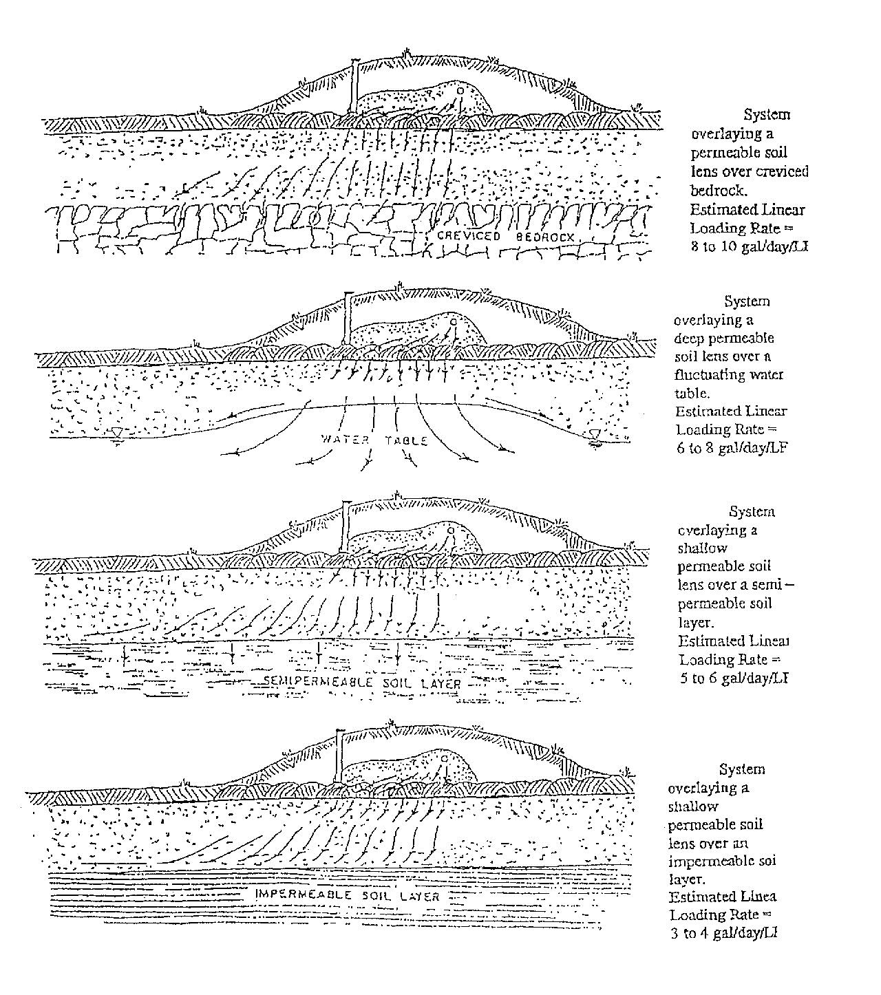
(J) Distribution Piping System
(1) The distribution piping shall comply with the requirements listed in Section 6.4-89.1(a)(4)(d) for Pressure Distribution piping.
(2) The pressure dosed laterals must be placed at the upper edge of the gravel beds on sloping sites, and equidistant throughout the gravel on level sites.
(3) Spacing of the perforated pressurized lines shall be based on the width of the gravel bed. The minimum number of pressurized lines based on the width of the gravel bed is as listed below:
(A) On slopes 1% or less:
|
WIDTH OF BED |
NUMBER OF LINES |
|---|---|
|
3' - 4' |
1 |
|
>4' - 6' |
2 |
|
>6' - 8' |
3 |
|
>8' -10' |
4 |
(B) On slopes greater than 1%:
|
WIDTH OF BED |
NUMBER OF LINES |
|---|---|
|
3' - 5' |
1 |
|
>5' - 10' |
2 |
The manifold may feed the lines either at one end or in the center.
(K) Dose Quantities
Small, frequent doses not exceeding 10% of the projected daily flow being discharged from the orifices used per dose after charging the manifold and laterals is recommended. A timer may be utilized to meet this. The maximum dose volume allowed shall not exceed 20% of the potential daily flow being discharged from the orifices during the dose cycle after charging the manifold and laterals. Devices that will utilize the disposal trenches of a field in an alternating series may be approved to achieve low flow volumes while disposing of the required daily volume, provided that the application rate per day is not exceeded in any one location.
(3) Sizing the At-Grade system.
(A) Effective absorption area required shall equal the maximum projected sewage flow from the building divided by the infiltration rate of the soil.
(B) Width of the gravel bed shall be determined by dividing the Linear Loading Rate by the soil infiltration rate, but shall not exceed ten (10') feet.
(C) The length of the gravel bed shall be determined by dividing the projected sewage flow by the Linear Loading Rate.
(D) Effective width and length are those dimensions of the gravel bed located down slope from the distribution pipe. Gravel placed uphill from the distribution pipe shall not be included in the required dimension. The area provided by the effective width and length shall be equal to or exceed the effective absorption area required. If the area provided does not equal or exceed the effective absorption area required, then the length of the At-Grade system shall be adjusted until the required effective absorption area is obtained or exceeded.
(4) Construction requirements for At-Grade systems
(A) The use of wheeled vehicles is prohibited for the purposes of ripping or chisel plowing, driving on areas that have been ripped or chisel plowed, moving the soil cover, or anytime the soil conditions are wet, moist, or saturated.
(B) Surface vegetation shall be mowed to native ground and the clippings removed.
(C) Construction staking or marking shall be provided of all components of the system prior to construction. The Environmental Health Services Division shall conduct a verification inspection of the construction staking or marking to confirm that the system will be constructed as designed.
(D) The soil surface shall be ripped or chisel plowed to a depth of eight (8") inches to ten (10") inches, with rippers set eight (8") inches to ten (10") inches apart. Initial ripping shall be performed in a path parallel to the contours of the land and only within the limits of the gravel bed. The interface of the native soil and the At-Grade soil shall be ripped after the gravel has been placed and just prior to At-Grade soil cover placement.
(E) No traffic is permitted on any ripped surface until after the gravel or soil cover has been placed.
(F) Temporary form boards required for the placement of material shall be removed prior to placement of the cover.
(G) Distribution to and through all laterals shall be balanced so all laterals and orifices receive an equal volume. The difference in head between any two lines, and the beginning and end orifice of the same line shall not exceed ten percent.
(H) Finished grade of the At-Grade system shall be established by track rolling and grooming by hand. Soil cover shall be conditioned with sufficient moisture to allow track rolling to a firm cohesive surface. All drainage work and erosion control shall be completed prior to final construction inspection. The soil cover shall be landscaped or seeded.
(I) The following minimum inspections prior to commencing construction or covering any elements of the system shall be required. Joint inspection by the designer, contractor, and Environmental Health Services Division may be required. All meetings and inspections shall be scheduled with the Solano County Environmental Health Services Division at least 48 hours in advance and shall occur during normal business hours:
(i) Pre-construction inspection where the following items shall be verified:
(aa) Imminent weather conditions are such that they will not create unsuitable soil conditions during construction.
(bb) Soil moisture in the area of the proposed At-Grade system is not so high as to cause smearing or compaction as a result of construction activities.
(cc) Layout and staking or marking of all components of the At-Grade system.
(dd) The source of soil fill material shall be designated and a sample made available.
(ii) Ripping of the soil.
(iii) Gravel placement and Hydraulic Test:
(aa) Function and setting of all control devices.
(bb) Squirt test of system.
(cc) Depth and location of gravel.
(dd) Water tightness of septic tank and dosing tank.
(iv) Final Inspection:
(aa) Depth and texture of final soil cover over the At-Grade system is verified. All construction elements are in general conformance with the approved plans and specifications. All performance wells are installed and erosion control has been completed.
(bb) A letter from the designer that the At-Grade system has been installed and is operating in conformance with the design specifications must be provided.
(5) Performance wells
(A) Performance well construction shall be in conformance with section 6.4-89(l)(1).
(B) A minimum of six (6) performance wells shall be installed. Two (2) performance wells shall be installed at the center of the gravel bed during construction. Two (2) performance wells shall be placed twenty-five (25') feet down gradient from the gravel bed, and two (2) performance wells shall be placed ten (10') feet up gradient from the gravel bed.
(c) Mound Systems
(1) Mound Siting Criteria
(A) A Mound systems shall not be installed in concave landscape formations, areas of seasonal saturation such as flood plains, vernal pools, drainage areas, areas that have been filled to artificially raise the separation to ground water or other limiting condition, cut or filled sites, or hummocky terrain.
(B) Areas proposed for the Mound system shall be undisturbed. Placement of Mound Systems into areas where removal of large trees, boulders, or rock outcroppings is required is not permitted.
(C) The minimum effective soil depth below the Mound System is twenty four (24") inches. A minimum twenty four (24") inches effective soil depth shall also extend a horizontal distance of at least twenty five (25') feet down gradient from the down slope edge of the proposed perimeter of the sand bed on sites with sloping terrain. On sites with flat terrain the required effective soil depth shall extend for twenty five (25') feet beyond the sand basal area on all sides and ends of the mound. Increasing the sand depth of a mound system beyond one (1') foot does not allow a decrease in the minimum effective soil depth below the mound system.
(D) The slope in the area of the mound system shall not exceed twelve and one-half (12 1/2 %) percent.
(E) The percolation rate of the soil twenty four (24") inches or less below the mound system shall be from 1 to 120 mpi.
(F) In addition to the other setbacks required by these standards, Mound Systems shall also comply with the following setbacks:
|
(i) |
Buildings and Structures |
|
|
|
Up gradient and laterally |
10 feet |
|
|
Down gradient |
25 feet |
|
(ii) |
Property Lines or Underground Utility Easements |
|
|
|
Up gradient and laterally |
10 feet |
|
|
Down gradient |
25 feet |
|
(iii) |
Areas of Geologic Instability |
100 feet |
(2) Mound Design Requirements
(A) Unless otherwise approved by the Environmental Health Services Division, a Mound system shall consist of at least a septic tank discharging to a dosing tank, which then pumps the sewage effluent under pressure through one or more pressure distribution laterals installed within the gravel of a distribution bed placed upon the ground surface. Exception: The Environmental Health Services Division may waive the requirement for a mound system utilizing an aerobic treatment unit to include a septic tank as a separate treatment process if so recommended or required by the manufacturer of the aerobic treatment unit or registered consultant. The mound shall be covered with soil.
(B) For commercial systems the wastewater quality in terms of BOD, soluble BOD, suspended solids, grease and oils, temperature, and volatile suspended solids shall be given. If the strength of the wastewater exceeds 5 day BOD mean value of 185 ppm and Total Suspended Solids mean value of 75 TSS, then pretreatment of the wastewater prior to disposal in the Mound System is required.
(C) Distribution Bed
(i) The distribution bed shall consist of a gravel bed placed upon a portion of a sand bed. The required area of the sand bed is known as the sand basal area.
(ii) Distribution beds shall follow natural contour of the ground. The distribution bed must be installed within a tolerance of three (3") inches vertically per one hundred (100') feet horizontally.
(iii) Only single distribution beds are acceptable.
(iv) Gravel Bed
(aa) The maximum width of any gravel bed is ten feet. However, every effort shall be made to make the gravel bed long and narrow for best performance of the Mound system.
(bb) The width dimension of the gravel bed shall be determined using the linear loading rates in Figure 3. When depth to a limiting condition is only twenty-four (24") inches, the linear loading rate shall not exceed four (4 gal/ft/day) gallons per lineal foot per day. Exception: If it can be demonstrated that wastewater flow will be vertical, as well as horizontal, a higher loading rate based on Figure 3 can be proposed.
(cc) The depth of the gravel bed shall be nine (9") inches total depth (six (6") inches below the laterals) for residential systems and twelve (12") inches total depth (nine (9") inches below the laterals) for commercial systems.
(dd) Drain rock used shall be double washed to reduce fines and range in size from 3/8 to 2 inches in diameter. The outer layer of the gravel bed shall be covered with Mirafi 140N geotextile fabric or equivalent. The infiltration rate of effluent onto the gravel shall not exceed the following:
(1) Residential Systems: 1.2 gallons/square foot/day
(2) Commercial Systems: 1.0 gallons/square foot/day
Lower values are encouraged.
(v) Sand Basal Area
(aa) Sand basal area is based upon the average percolation rate, soil morphological conditions, and projected daily sewage flow.
(bb) The sand fill shall be level and extend a minimum of twenty-four (24") inches horizontally level beyond the edge of the gravel bed on all sides, and then uniformly slope as determined by the mound dimensions. On slopes greater than two (2%) percent, the twenty-four (24") inch dimension may be reduced to twelve (12") inches on the uphill side of the distribution bed.
(cc) On slopes greater than one (1%) percent, the sand basal area uphill and beyond the longitudinal ends from the gravel bed shall not be included in the calculations for the required absorption area.
(dd) Sand shall comply with the specifications in figure 4, or as otherwise approved by the Environmental Health Services Division.
(vi) Distribution Piping System
The distribution piping shall comply with the requirements listed in Section 6.4-89.1(a)(4)(d) for Pressure Distribution piping.
Spacing of the perforated pressurized lines shall be based on the width of the gravel bed. The minimum number of pressurized lines based on the width of the gravel bed are as listed below:
|
WIDTH OF BED |
NUMBER OF LINES |
|---|---|
|
3' - 4' |
1 |
|
>4' - 6' |
2 |
|
>6' - 8' |
3 |
|
>8' -10' |
4 |
Figure 3: Linear Loading Rates for Mound Systems
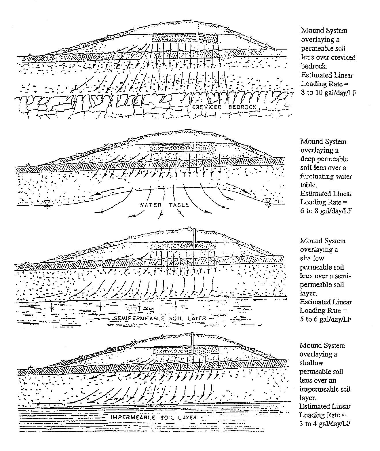
Figure 4: Sand Specifications for Mound Systems.
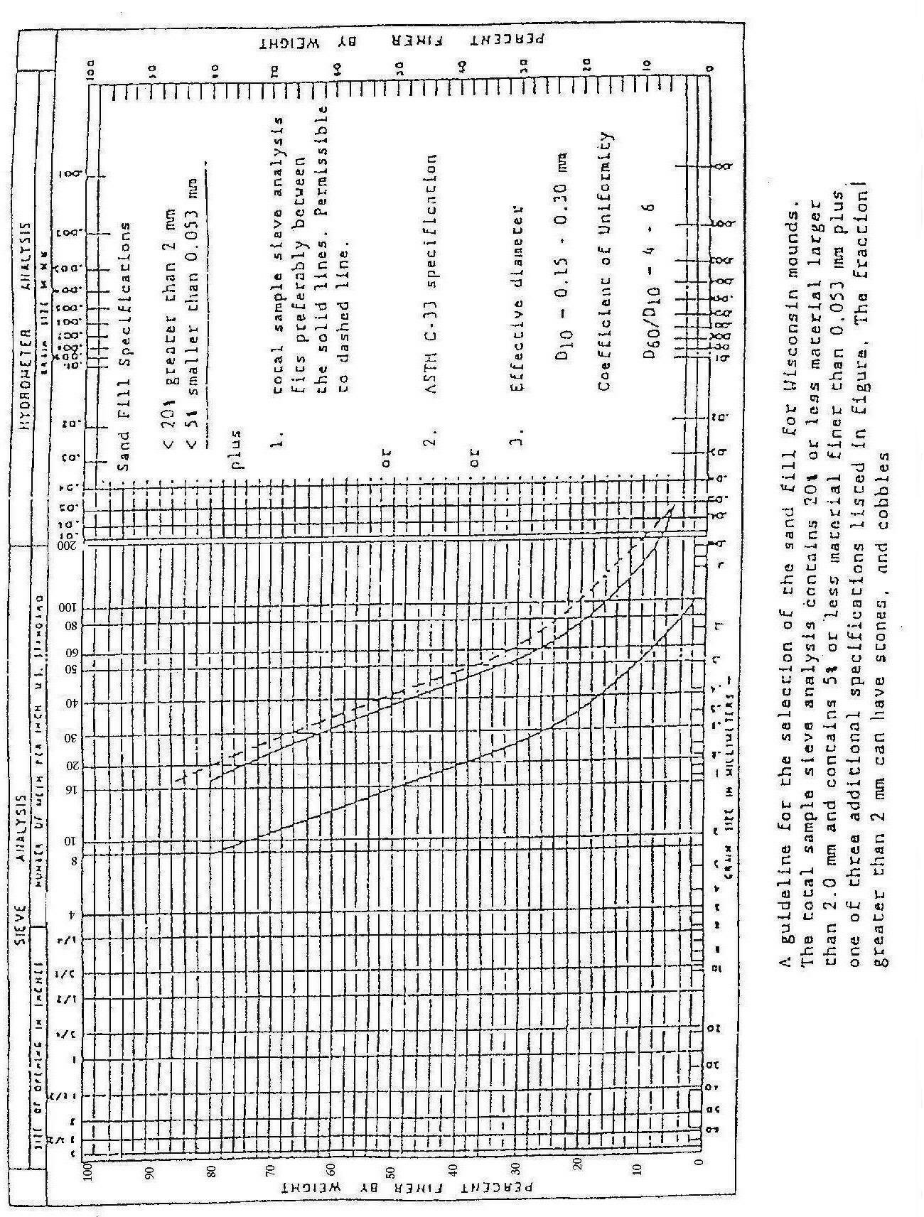
(D) Soil Cover
(i) Texture and structure of the soil cover shall be equal or better than the soil existing at the site. The permeability range shall be between 10 - 60 mpi. Use of manufactured soil or high clay content soils that do not allow gas exchange to occur is prohibited.
(ii) The soil cover shall be mounded to a height of twelve (12") inches above the distribution bed, with a peak of eighteen (18") inches at the center of the mound. The soil cover shall extend beyond the mound a minimum of four (4') feet beyond the uphill side and longitudinal ends of the distribution bed, and on the downhill side, a minimum of:
|
4' |
on slopes from |
0 - 2% |
|
6' |
on slopes from |
>2 - 4% |
|
8' |
on slopes from |
>4 - 6% |
|
10' |
on slopes from |
>6 - 8% |
|
12' |
on slopes from |
>8 - 12 1/2 % |
(E) Dose Quantities
Small, frequent doses not exceeding 10% of the projected daily flow being discharged from the orifices used per dose after charging the manifold and laterals is recommended. A timer may be utilized to meet this. The maximum dose volume allowed shall not exceed 20% of the potential daily flow being discharged from the orifices during the dose cycle after charging the manifold and laterals. Devices that will utilize the disposal trenches of a field in an alternating series may be approved to achieve low flow volumes while disposing of the required daily volume, provided that the application rate per day is not exceeded in any one location.
(3) Sizing the mound system (refer to Figures 5 and 6).
(A) Effective absorption area of gravel required shall equal the projected sewage flow from the building divided by the infiltration rate of the gravel.
(B) Taking the linear loading rate and dividing it by the infiltration rate of the gravel shall determine effective width of the gravel bed.
(C) Taking the effective absorption area of gravel required and dividing it by the width of the gravel bed shall determine the effective length of the gravel bed.
(D) Uphill fill depth of sand shall be one (1') foot.
(E) Downhill fill depth of sand shall be the uphill fill depth added to the gravel bed width multiplied by the slope, i.e.: uphill fill + (%slope)(gravel bed width).
(F) Vertical depth of gravel bed is as indicated in section 6.4-89.1(c)(2)(c)4(c).
(G) Down slope width is the sum of the downhill fill depth plus the vertical depth of the gravel plus one, multiplied by three, multiplied by the down slope correction factor of Table 8, i.e.: {(e)+(f)+1}(3)(down slope correction factor)
(H) Upslope width is the sum of uphill fill depth plus the vertical depth of the gravel plus one, multiplied by three, multiplied by the up slope correction factor, i.e.: {(d)+(f)+1}}(3)(up slope correction factor).
(I) End width is the sum of the average of uphill and downhill sand fill depth plus the vertical depth of the gravel plus one multiplied by three, i.e.: [{(d)+(e)}/2 +(f) + (i)](3).
(J) Required sand basal area is the projected daily flow from the building divided by the infiltration capacity of the soil.
(K) Available sand basal area shall be greater than the required sand basal area. Available sand basal area is
(i) On flat ground: the length of the gravel bed multiplied by the total width of the sand bed.
(ii) On sloped ground: the length of the gravel bed multiplied by the sum of the width of the gravel plus the down slope width, i.e. (c){(b)+(g)}.
(M) If sufficient area is not available, then the down slope width or gravel bed length shall be increased.
|
Slope % |
Down slope Correction Factor |
Up slope Correction Factor |
|---|---|---|
|
0 |
1.00 |
1.00 |
|
2 |
1.06 |
0.94 |
|
4 |
1.14 |
0.89 |
|
6 |
1.22 |
0.86 |
|
8 |
1.32 |
0.80 |
|
10 |
1.44 |
0.77 |
|
12 1/2 |
1.57 |
0.73 |
(4) Construction requirements for a mound system
(A) The use of wheeled vehicles is prohibited for the purpose of ripping or chisel plowing, driving on areas that have been ripped or chisel plowed, driving on the sand fill, placing or moving the soil cover, or anytime the soil conditions are wet, moist, or saturated.
(B) Surface vegetation shall be mowed to native ground and the clippings removed.
(C) Construction staking or marking shall be provided of all components of the system prior to construction. The Environmental Health Services Division shall conduct a verification inspection of the construction staking or marking to confirm that the system will be constructed as designed.
(D) The soil surface shall be ripped or chisel plowed to a depth of eight (8") inches to ten (10") inches, with rippers set eight (8") inches to ten (10") inches apart. Initial ripping shall be performed in a path parallel to the contours of the land, and only within the limits of the sand base. The interface of the native soil and the mound soil shall be ripped after all the sand has been placed and just prior to mound cover placement. No traffic is permitted on any ripped surface until after the sand or soil cover has been placed.
(E) The sand fill shall be uniformly placed and compressed by track rolling to a neat line and to a grade of 3:1, with a horizontal tolerance not exceeding one quarter (1/4') foot horizontally.
(F) Temporary form boards required for placement of material shall be removed prior to placement of cover.
(G) Distribution to and through all laterals shall be balanced so all laterals and orifices receive an equal volume. The difference in head between any two lines, and the beginning and end orifice of the same line shall not exceed ten percent.
(H) Finished grade of the mound shall be established by track rolling and grooming by hand. Soil cover shall be conditioned with sufficient moisture to allow track rolling to a firm cohesive surface. All drainage work and erosion control shall be completed prior to final construction inspection. The soil cover shall be landscaped or seeded.
(I) The following minimum inspections prior to commencing construction or covering any elements of the system shall be required. Joint inspection by the designer, contractor, and Environmental Health Services Division may be required. All meetings shall be scheduled with the Solano County Environmental Health Services Division at least 48 hours in advance and shall occur during normal business hours:
(i) Pre-construction inspection where the following items shall be verified:
(aa) Imminent weather conditions are such that they will not create unsuitable soil conditions during construction.
(bb) Soil moisture in the area of the proposed mound system is not so high as to cause smearing or compaction as a result of construction activities.
(cc) Layout and staking or marking of all components of the mound system.
The source of soil fill material shall be designated and a sample made available.
(ii) Sand Placement: Ripping of the soil, sand quality, placement, and depth.
(iii) Gravel placement and Hydraulic Test:
(aa) Function and setting of all control devices.
(bb) Squirt test of system.
(cc) Depth of gravel.
(dd) Water tightness of septic tank and dosing tank.
(iv) Final Inspection:
(aa) Depth and texture of final soil cover is verified. All construction elements are in general conformance with the approved plans and specifications. All performance wells are installed and erosion control has been completed.
(bb) A letter from the designer that the Mound system has been installed and is operating in conformance with the design specifications must be provided.
(5) Performance wells
(A) Performance well construction shall be in conformance with section 6.4-89(l)1.
(B) A minimum of eight (8) performance wells shall be installed. Two (2) performance wells shall be installed in the gravel bed extending to the sand bed during construction of the distribution bed. Two performance wells shall be placed at the toe of the sand bed. Two (2) performance wells shall be placed twenty-five (25') feet down gradient from the sand bed, and two (2) performance wells shall be placed ten (10') feet up gradient from the sand bed.
(d) Sand Filter Systems
(1) Sand filters receive septic tank effluent under pressure. There are currently two approved types of sand filter systems. They are:
(A) Intermittent Sand Filter System (ISF). Wastewater passes through the filter once to achieve the total and fecal coliform reductions.
(B) Recirculating Sand Filter System (RSF). In addition to reducing the coliform content of the wastewater, the RSF also reduces the nitrate content of the wastewater. Wastewater is recirculated up to four (4) times through the RSF to achieve the reduction of the total and fecal coliforms and nitrate contents. Each time the wastewater is circulated through the RSF, 75 to 80 percent is recirculated through the unit and 20 to 25 percent of the wastewater exits the unit.
(2) The components of a Sand Filter are a containment pit or structure with a waterproof liner, distribution piping, gravel, sand, collection drain system, and a pump.
(3) A Sand Filter is used prior to disposal of effluent into a Pressure Distribution system, At-Grade system, Mound system or other alternative system requiring pretreatment of effluent prior to disposal. Refer to the appropriate sections of these standards for these specific methods of sewage disposal.
(4) A Sand Filter is an approved pretreatment device if built according to these standards. The minimum effective soil depth below an At-Grade, Pressure Distribution, or Mound system preceded by a sand filter is twenty-four (24") inches. No further reduction in setback from a limiting condition is granted for use of a sand filter with a Mound system. Increasing the sand depth of a sand filter beyond two (2') feet does not allow a decrease in the required depth of the minimum effective soil above a limiting condition.
(5) Placement of a sand filter shall comply with all setbacks established in these standards for the placement of septic tanks.
(6) Sand Filter Design Criteria
(A) Containment Pit or Structure
(i) A pit shall be dug into the ground for installation of the sand filter.
(ii) The pit shall have walls constructed of at least pressure treated or redwood heart grade materials of at least 1/2" thickness. All fasteners shall be flush, counter sunk or recessed.
(iii) The walls shall be constructed so that the top is at least six (6") inches above natural grade.
(iv) A geotextile fabric in a thickness appropriate to protect the liner shall be placed over all wood surfaces.
(v) The bottom of the pit must have a bedding layer of sand installed. The sand must be graded to provide a slope from the outer edges towards the point of the under drain system.
(vi) At least a 30 mil PVC liner shall be installed. All seams of the liner must be factory heat or solvent welded. Factory fabricated boots must be used where any plumbing lines pass through the liner. The boots must extend into the liner and be watertight. The liner must be large enough to cover the bottom and extend up the sides of the support structure with enough excess to allow the liner to be firmly anchored.
Figure 5: Plan and profile view of Mound System
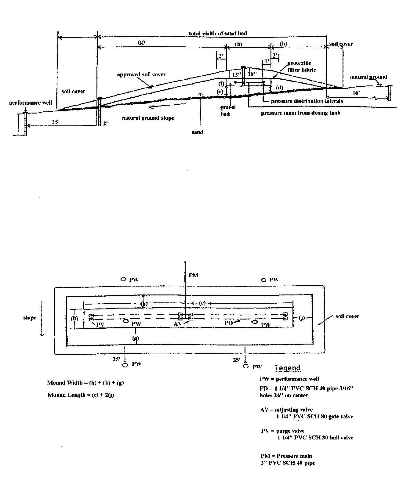
(vii) The liner must be covered with adequate sand to bed the liner and protect it from puncture.
(B) Filter Bed Sizing
(i) Loading rate shall not exceed 1.2 gallons /day/square foot for an intermittent sand filter and 4 gallons/sq.ft./day for a recirculating sand filter.
(ii) The surface area required for the filter bed shall be determined by dividing the wastewater flow by the loading rate.
(C) Depth of sand shall be a minimum of twenty-four (24") inches. Unless approved otherwise by the Environmental Health Services Division, sand specifications in intermittent sand filters shall comply with the following:
|
Sieve Size |
Percent Passing |
|---|---|
|
# 3/8 |
100 |
|
# 4 |
|
|
# 8 |
|
|
# 16 |
|
|
# 30 |
|
|
# 50 |
|
|
# 100 |
0-2 |
|
# 200 |
0-1 |
Effective size and uniformity:
D10 = 1.5 - 2.5mm
Cu = 1 - 4
and sand specifications for a recirculating sand filter shall comply to the following:
|
Sieve Size |
Percent Passing |
|---|---|
|
3/8 |
100 |
|
# 4 |
|
|
# 8 |
|
|
# 16 |
0-4 |
|
# 30 |
0-2 |
|
# 50 |
0-1 |
|
# 100 |
0-1 |
|
#200 |
0-1 |
Effective size and uniformity:
D10 = 1.5 - 2.5mm
Uc = 1-3
The sand shall be analyzed by wet-sieve analysis using ASTM method C-117 or equivalent. Prior to placement of the sand, the Environmental Health Services Division must be provided with a copy of the sieve analysis, certified as to conformance with the standards by the consultant.
(D) Small, frequent doses not exceeding 10% of the projected daily flow being discharged from the orifices used per dose after charging the manifold and laterals is recommended. A timer may be utilized to meet this. The maximum dose volume allowed shall not exceed 20% of the potential daily flow being discharged from the orifices during the dose cycle after charging the manifold and laterals. Devices that will utilize the disposal trenches of a field in an alternating series may be approved to achieve low flow volumes while disposing of the required daily volume, provided that the application rate per day is not exceeded in any one location.
(E) The distribution piping shall comply with the requirements listed in Section 6.4-89.1(a)(4)(d) for Pressure Distribution piping.
(F) Slotted under drain pipe must be at least four (4") inch diameter PVC collection pipe. The under drain pipe must be properly positioned within the lower gravel layer.
(G) Pressure distribution must be used from the sand filter to the disposal field. Effluent from the sand filter may gravity flow into a separate dosing tank, or into a pump chamber located within the sand filter.
(7) Performance wells shall be required in the sand filter. At least two wells shall be provided. One well shall extend to the bottom of the sand layer, the other to the top.
(8) The following minimum inspections prior to commencing construction or covering any elements of the system shall be required. Joint inspection by the designer, contractor, and Environmental Health Services Division may be required. All meetings shall be scheduled with the Solano County Environmental Health Services Division at least 48 hours in advance and shall occur during normal business hours:
(A) Pre-construction inspection where the construction staking or marking of the sand filter is provided and construction procedures are discussed.
(B) Sand Placement and quality.
(C) Hydraulic Test:
(i) Function and setting of all control devices.
(ii) Squirt test of system.
(iii) Water tightness of septic tank and dosing tank.
(D) Final Inspection
(i) All construction elements are in general conformance with the approved plans and specifications. All performance wells are installed and erosion control has been completed.
(ii) A letter from the designer that the Sand Filter system has been installed and is operating in conformance with the design specifications must be provided.
(e) Aerobic Treatment Unit (ATU)
(1) ATUs provide biological reduction of wastewater strength through pretreatment prior to disposal of sewage into a Pressure Distribution, At-Grade, Mound, or other alternative system. They typically use fixed or suspended films that support biological growth, and air blowers.
(2) Construction Requirements
(A) The ATU shall be listed by NSF as meeting the NSF Standard 40, Class 1 performance evaluation, or have certification by a third party listing agency as complying with NSF Standard 40. The ATU shall be manufactured and installed in accordance with the design specifications used to determine compliance to NSF Standard 40.
(B) All tanks housing an ATU shall be structurally sound, water tight and capable of withstanding 1,000 pounds of weight.
(C) The designer and installer shall follow the manufacturer’s design, installation, construction, and operations procedure.
(D) The applicant must demonstrate that a written maintenance contract has been obtained for the proposed ATU to assure satisfactory post construction operation and maintenance. A maintenance agreement must be maintained valid for the life of the ATU.
(E) The ATU shall be preceded by a septic tank unless it can be demonstrated that such a requirement will adversely affect the performance of the ATU.
(3) The following minimum inspections prior to commencing construction or covering any elements of the system shall be required. Joint inspection by the designer, contractor, and Environmental Health Services Division may be required. All meetings shall be scheduled with the Solano County Environmental Health Services Division at least 48 hours in advance and shall occur during normal business hours:
(A) Pre-construction inspection where the construction staking or marking of the ATU is in place and installation procedures is discussed.
(B) Test of the ATU:
(1) Function and setting of all control devices and alarms.
(2) Water tightness of septic tank, ATU, and any dosing tank.
(C) Final Inspection
(i) A letter from the designer that the ATU system has been installed and is operating in conformance with the design specifications shall be provided.
(ii) A valid, signed maintenance agreement between the applicant/property owner and service provider must be provided.
(Ord. No. 1609, §18; Ord. No. 1655, §§36, 37, 38, 39, 40, 41, 42, 43, 44, 45, 46, 47)
ARTICLE IX. DEFINITIONS
6.4-90 Definitions
(a) The definitions contained in this section shall only apply to this Chapter.
(b) The following words and phrases, whenever used in this Chapter, shall have the meaning hereafter defined:
(1) Abandoned On-Site Sewage Disposal System - A cesspool, septic tank, holding tank, pit privy, dosing tank, or interceptor that is no longer used, or that is not connected to a structure or building drain, or that receives no wastewater and has not been destroyed in a manner approved by the Environmental Health Services Division.
(2) Alternative System - A sewage disposal system that uses an advanced method of effluent treatment and/or distribution and is designed by a Civil Engineer, Certified Engineering Geologist or Environmental Health Specialist registered in the State of California. An alternative system is designed to mitigate soil and/or groundwater conditions which render a lot inappropriate for a standard septic system, or to mitigate severely inadequate replacement area for repair or replacement of an existing, improperly functioning on-site sewage disposal system. An alternative system does not include a standard system that only uses a pump to deliver effluent to a non-pressurized disposal field complying with all surface and subsurface set back requirements.
(3) Approved On-Site Sewage Disposal System - is a system for which an approved final permit is on file with the Environmental Health Services Division and for which the conditions upon which the permit was approved have not changed.
(4) ASTM - American Society for Testing Materials.
(5) Bedrock - Solid rock, which may have fractures, and that lies beneath soils or other unconsolidated material. Material is considered to be rock when over fifty (50%) percent by volume is composed of coarse fragments that are retained on a #10 sieve.
(6) Bedroom - Any room that can be used for sleeping purposes. For purposes of sizing the on-site sewage disposal system, habitable rooms with a floor area equal to or greater than 70 square feet and designed to provide privacy to the occupant will typically be considered bedrooms. Such rooms include, but are not limited to, those designated on plans as bedrooms, lofts, sewing rooms, dens, offices, and game rooms. A closet, or lack thereof, shall not determine whether a room is considered a bedroom. Kitchens, bathrooms, laundry rooms, rooms with large entry ways lacking doors and designed that the installation of a door would require a building permit, rooms with a fuel-burning water heater, and rooms not meeting the Uniform Housing Code as approved by Solano County requirements for a bedroom may not be considered bedrooms at the discretion of the Environmental Health Services Division.
(7) Bulk Density - The mass of dry soil per unit of bulk volume.
(8) Building Sewer - The solid pipe connecting the building drain to a septic tank, interceptor, or sanitary sewer.
(9) Cesspool - A lined or unlined excavation in the ground that receives wastewater, allows the separation of solids and liquids, retains the solids and allows liquids to seep into the surrounding soil.
(10) Chemical Toilet - A non-flushing, non-recirculating toilet facility wherein waste is deposited directly into a chamber that may contain a solution of water and chemicals.
(11) Cleanout - A fitting inserted into a piping system, with a removable plug whereby access to the pipe is obtained for the purposes of cleaning or unstopping.
(12) Coarse Fragments - Rock or consolidated mineral particles greater than 2.00 mm in diameter.
(13) Community Sewage Disposal System - a system that accepts sewage from two or more separate lots. Includes public sewer and community on-site sewage disposal system.
(14) Construction permit: Gives approval for specific on-site sewage disposal system work as detailed and conditioned in the construction permit and these standards.
(15) Cumulative impacts - The persistent and/or increasing effects of on-site sewage disposal systems resulting from the density of the discharges from such systems in relation to the assimilative capacity of the ground environment. Examples include salt or nitrate additions to groundwater, nutrient enrichment of surface water, and hydraulic interference both with groundwater and between adjacent on-site sewage disposal systems.
(16) Cutbank - Any naturally occurring or man-made slope that has greater than 30 percent slope and extends vertically at least 3 feet from the toe of the slope to the top of the slope. Includes cuts supported by retaining walls.
(17) Disposal Field - The portion of the on-site sewage disposal system and the surrounding area used for dispersion of the liquid portion of wastewater into the soil. Consists of one or more leachlines or other methods approved by the Environmental Health Services Division for wastewater dispersion.
(18) Distribution Box - A watertight structure that receives effluent from the septic tank and distributes it to two or more header pipes to the disposal field.
(19) Diversion Valve - A device that receives wastewater through one inlet and distributes it to two (2) or more outlets, only one of which is used at a given time.
(20) Domestic Water Supply Reservoir - An existing or proposed open, uncovered reservoir used or intended to impound water for human consumption or domestic purposes, including a planned reservoir.
(21) Dosing Tank - A water tight receptacle constructed of approved materials designed to receive and store clarified effluent and convey it to a pretreatment device or a disposal field under positive pressure. The dosing tank is equipped with a pump(s), effluent screen, and level control and alarm floats.
(22) Drainage Area - All the land that can, or may, drain into a domestic water supply reservoir, whether or not the topographical configuration is artificially or naturally caused.
(23) Drainage Well - A well constructed for the purpose of disposing wastewater, hazardous materials, storm water or drainage water.
(24) Dwelling- Any structure, or portion thereof, which is used, intended, or designed to be occupied for human living purposes including, but not necessarily limited to, houses, houseboats, mobile homes, hotels, motels, apartments, and condominiums.
(25) Effective Sidewall Area of Trench - The portion of the sidewalls of a leaching trench containing effective soil and extending upward from the bottom of the trench to the approximate height of the invert of the perforated pipe installed in the leaching trench.
(26) Effective Soil - Undisturbed, native soil having an acceptable percolation rate and located above a limiting condition including, but not limited to the highest level of permanent, perched, or seasonal ground water, bedrock, fractured or fissured rock, or any layer that impedes movements of water or air, or growth of plant roots, or that will not retain sewage for an adequate time period to allow for proper treatment of sewage prior to it reaching groundwater. Effective soil does not include fill material.
(27) Ephemeral Stream - An observable watercourse that flows only in direct response to precipitation. It receives no water from springs and no long-term supply from melting snow or other surface source. Its stream channel is at all times above the local water table. Any watercourse that does not meet this definition is to be considered a perennial stream for the purposes of these standards.
(28) Equal Distribution- A method of sewage effluent disposal that distributes the flow to the disposal field in such a manner that all distribution lines receive an equivalent volume of effluent concurrently, and if pressurized, evenly throughout their length.
(29) Existing On-Site Sewage Disposal System - An on-site sewage disposal system in existence prior to the effective date of these standards.
(30) Experimental System - Those systems that:
(a) Are alternative systems installed into areas where surface and/or subsurface conditions do not comply with these standards; and/or
(b) Are not allowed for individual on-site sewage disposal for subdivision of land or new construction without being approved and under permit from the Regional Water Quality Control Board having jurisdiction; and/or
(c) Use construction materials other than those noted for standard systems and non-experimental alternative systems in these standards.
(31) Failing or Failed System- An on-site sewage disposal system which causes or results in any of the following conditions:
(a) Failure to accept wastewater discharge creating a backing of wastewater into the structure served by the system.
(b) The discharge of wastewater to the surface of the ground.
(c) The discharge of wastewater to surface waters or groundwater.
(d) The lack of an unsaturated vertical soil separation between the bottom of a disposal field and seasonal high groundwater.
(e) Wastewater level in a disposal field standing at least one inch above the invert of the perforated pipe or other means of wastewater distribution within the disposal field.
(f) An alternative system with sample results exceeding 240,000/100 ml most probable number (MPN) total coliform bacteria and/or 2.2 MPN fecal coliform from purged wells located twenty five (25') feet or further down gradient. Exception: if the up gradient performance wells have similar contamination levels as down gradient wells, then the contamination is deemed to be background in the area.
(32) Fractured Rock - Material that is composed of over fifty (50%) percent coarse fragments by volume.
(33) Greywater - Untreated household wastewater that has not come in contact with toilet or food wastes. Greywater includes used water from bathtubs, showers, wash basins and water from clothes washing machines and laundry tubs. It does not include wastewater from kitchen sinks, dishwashers or laundry water from soiled diapers.
(34) Groundwater - Subsurface water that is in the zone of saturation. Includes perched water tables, shallow regional groundwater tables or aquifers, or zones that are seasonally, periodically, or permanently saturated.
(35) Hardpan - An irreversibly hardened layer caused by the cementation of soil particles. The cementing agent may be silica, calcium carbonate, iron, or organic matter.
(36) Header Pipe- The solid line that receives wastewater from a manifold or distribution box and conveys it to the disposal field.
(37) Holding Tank - A water tight receptacle designed to receive and store wastewater for removal and disposal at another location.
(38) High Water Level - The highest known or recorded flood water elevation during a ten year event of any lake, stream, pond, reservoir, ditch, canal, culvert, or drainage way.
(39) IAPMO - International Association of Plumbing and Mechanical Officials.
(40) Impermeable Soil Layer - Any layer of soil having a percolation rate slower than 120 minutes per inch (1/2 inch per hour).
(41) Incompatible Use - Any activity or land use that would preclude or damage an area for use as a sewage disposal site. Includes but is not limited to the construction of buildings, roads or other structures that may result in the compaction, displacement, or removal of existing soil.
(42) Industrial Waste - Any liquid, gaseous, radioactive, or solid waste substance, or combination thereof, resulting from any process of industry, manufacturing, trade, or business, or from the development or recovery of any natural resources.
(43) Invert - The lowest internal portion of the internal cross-section of a pipe or fitting.
(44) Leach Line - A trench with vertical sides and substantially flat bottom and filled with drain rock into which perforated pipe or other means of wastewater distribution has been laid.
(45) Limiting Condition - Includes, but is not restricted to the highest level of permanent, perched, or seasonal ground water, hardpans, claypans, impermeable soil, weak or massively structured clays or silty clays, coarse sand, cemented soil, plastic soil, fragipans, compacted soil, bedrock, fractured or fissured rock, saprolite, clay soil, soil containing more then fifty (50%) percent coarse fragments by volume as retained on a #10 sieve, any layer that impedes movements of water or air, or growth of plant roots, or that will not retain sewage for an adequate time period to allow for proper treatment of sewage prior to it reaching groundwater.
(46) Limiting Soil Layer - Also known as restrictive soil layer is the portion of the soil profile that most restricts the successful operation of a leachfield to treat and dispose of sewage effluent without causing contamination.
(47) Lot - as defined by Chapter 26 of the Solano County Code.
(48) Manifold Pipe - Tightline that interconnects perforated pipe in a disposal field, or which receives wastewater from a septic tank or dosing tank for distribution to leach lines.
(49) Mottles - Spots or streaks of contrasting soil colors. For purposes of groundwater determination this term shall refer to those features formed in the soil during periods of saturation from the process of reduction, translocation, and oxidation of iron and manganese found in some soils. Such features remain evident in dry soils after the saturation event has occurred. These redoximorphic features of soils (mottles and gleying) are used to indicate poor aeration, ground water levels, and lack of drainage. Soils lacking iron and manganese, such as sand, will not show mottles even if saturated.
(50) On-Site Sewage Disposal System - Also termed septic system, or sewage disposal system, means any system of piping, treatment devices, appurtenant components, or other facilities that convey, store, treat, or dispose of wastewater onto or into the ground for subsurface treatment and disposal on the same lot from which the waste flow is generated. This term includes both standard and alternative systems. Individual on-site sewage disposal systems dispose of sewage effluent into a private disposal field located on the lot where the sewage originates and is privately owned and operated by the lot owner. Community on-site sewage disposal systems receive sewage from two or more separate lots and dispose of it into a shared disposal field located on another separate lot. A community on-site sewage disposal system is owned, operated, and maintained in accordance with the Solano County General Plan by a government agency, public utility, maintenance district, or other similar entity approved by the Local Agency Formation Commission and is approved by and operated under permit from the Regional Water Quality Control Board.
(51) Operation permit: Gives approval for operation of an alternative or experimental system in conformance with the operation permit conditions and these standards.
(52) Perched Water - A subsurface body of water separated from the main groundwater body by a relatively impermeable stratum above the main groundwater body.
(53) Percolation Test - A soil test performed to estimate the absorption capability of the soil.
(54) Perennial Stream - A river or stream which flows continuously, or which flows in response to a spring source, and which is, during the wet season, confluent with a local water table. A perennial stream may or may not flow year round, but does flow in response to surface or subsurface water not associated exclusively with a rain event.
(55) Perforated Pipe - Pipe used in the dispersion of wastewater into leach lines.
(56) Pit Privy - A structure used for disposal of human waste without the aid of water. It consists of a pit or vault in the ground into which human waste is deposited.
(57) Plumbing Fixtures - Receptacles, devices or appliances which are supplied with water, or which receive liquid or liquid-borne wastes and discharge such as wastes into the drainage system to which they may be directly or indirectly connected. Industrial or commercial tanks, vats and similar processing equipment are not considered plumbing fixtures.
(58) Pressure Distribution - A method of effluent distribution designed to distribute wastewater equally and evenly throughout an absorption field by placing the liquid effluent under pressure in the pipe.
(59) Program Manager - The Program Manager of the Solano County Environmental Health Services Division.
(60) Property Owner - The person(s), firm(s), trust(s), or other entity(ies) listed in the records of the Solano County Assessor as the current owner of any subject lot.
(61) PVC - Polyvinyl chloride.
(62) Registered Consultant - is a Registered Civil Engineer, Registered Geologist, Certified Engineering Geologist, Registered Environmental Health Specialist, or Certified Professional Soil Scientist. All Registrations must be by the state of California.
(63) Reserve Area - Also known as “replacement area”, is an area on a lot equal in size and in suitability to the existing leachfield designated for future placement of a new sewage disposal system complying with these standards.
(64) Repair - The installation, modification, or replacement of any portion of a sewage disposal system or appurtenant feature necessary to eliminate or prevent a public health hazard, abate a nuisance, prevent the pollution of surface and ground waters caused by a failed or failing on-site sewage disposal system, or correct a violation of these standards. It may include repair or replacement of a disposal field, septic tank, piping, or any appurtenant components.
(65) Riser - A structure that allows access to the access ports of a septic tank, dosing tank, or interceptor.
(66) Sanitary Sewer - Also called “sewer”, is a sewer system owned or operated by a city, town, municipal corporation, county, political subdivision of the state, or other approved ownership which consists of a collection system and necessary trunks, pumping facilities and a means of final treatment and disposal and which has been approved and is under permit from the appropriate California Regional Water Quality Control Board.
(67) Sanitary Tee - A pipe extending above and below the liquid level in a septic tank, dosing tank, interceptor or other receptacle that is attached to the inlet or outline pipe of said tanks.
(68) Saturated Soil - The condition of soil when all available soil pore space is occupied by water and the soil is unable to accept additional moisture. In fine textured soils, the free water surface may not be apparent. The highest level of saturation can be estimated by the highest extent of soil mottling or gleying.
(69) Scum - A mass of sewage solids floating at the surface of wastewater within a septic tank, interceptor, or dosing tank, and which is buoyed up by entrained gas, grease, or other substances.
(70) Seepage Pit - Any excavation in the ground five feet or more in depth that receives and disposes of septic tank effluent.
(71) Septage - The solid and liquid contents of a septic tank, interceptor, holding tank, pit privy, dosing tank, chemical toilet, or on-site sewage disposal system. Also referred to as “cleanings” or “pumpings”.
(72) Septic Tank - A watertight tank which receives and partially treats wastewater through processes of sedimentation, flotation, and bacterial action so as to separate solids from the liquid in the wastewater and that discharges the liquid directly to a disposal field or dosing tank.
(73) Sewage - Any liquid waste containing water mixed with animal or vegetable matter, soaps, detergents, or chemicals in suspension or solution. Liquid waste includes kitchen, bath, laundry, office, processing and kennel wastes from residential, commercial, industrial, and agricultural buildings, facilities, or locations.
(74) Slope - The rate of fall or drop in elevation per 100 feet of the ground surface, or fraction thereof. It is expressed as percent of grade.
(75) Soil - Unconsolidated earthen materials over bedrock which is 2 millimeters in diameter or smaller and which falls within a soil textural class as specified in the USDA Soil Triangle.
(76) Soil Color - The moist color of soil based on Munsell soil color charts.
(77) Soil Horizon - A layer of a soil that is distinguishable from adjacent layers by characteristic physical properties such as structure, color, texture, or by chemical composition, including content of organic matter or degree of acidity or alkalinity.
(78) Soil Profile - An excavation displaying soil horizons in an area proposed for wastewater disposal to ascertain its suitability for that purpose. Characteristics of soil examined in a soil profile may include soil structure, soil texture, color, impervious layers, or evidence of groundwater as determined by direct observation or presence of soil mottles.
(79) Soil Structure - The arrangement of primary soil particles into compound particles or clusters that are separated from adjoining aggregates and have properties unlike those of an equal mass of unaggregated primary soil particles.
(80) Soil Texture - The relative proportions of sand, silt, and clay, as defined by the classes of the USDA Soil Triangle.
(81) Spring - A flow of water from the earth that occurs spontaneously where the water table stratum emerges to the surface of the earth. This term includes but is not limited to gravity springs, artesian springs, seepage springs, tubular springs, and fissure springs.
(82) Standard System - An on-site sewage disposal system that uses gravity to disperse effluent throughout the disposal field, and in which no pretreatment device is utilized. This term includes systems that use a pump to transport effluent received from the septic tank to an uphill disposal field where the effluent is then dispersed by gravity into an absorption field placed in an area with surface and subsurface features complying with these standards.
(83) Structure - Any building including, but not limited to, swimming pools, above ground pools, mobile homes, porches and steps (whether covered or uncovered), breezeways, roofed patios, decks, carports, covered walks, covered driveways, or similar structures or appurtenances.
(84) Subdivision - The division of land as defined by the Solano County Subdivision Ordinance.
(85) Tentative Map - Includes both tentative map and tentative parcel map, as used in Chapter 26 of the Solano County Code.
(86) Tight Line - All watertight piping located downstream of the building drain. This term includes, but is not necessarily limited to, the building sewer, manifold, header pipe, and transmission line.
(87) UL - Underwriter’s Laboratory.
(88) UPC - Uniform Plumbing Code.
(89) Unstable Landform - Areas showing evidence of mass down slope movement such as debris, flow, landslides, rockfalls, and hummocky hill slopes, or actively eroding bluffs.
(90) USDA - United States Department of Agriculture.
(91) Well - Any artificial excavation of approximately tubular shape constructed by any method for the purpose of extracting water from, or injecting water or other liquid into the ground; for observation of groundwater for any reason; for the exploration of the subsurface of the earth; for removal of substances from soil or groundwater; or for cathodic protection.
(Ord. No. 1609, §18; Ord. No. 1655, §48, §49)