


Chapter 12.04
ENGINEERING DEVELOPMENT CODE1
Sections:
Article I. In General
12.04.020 Administration – Enforcement.
Article II. Administration
12.04.060 Definition of terms.
12.04.070 Standard specifications.
12.04.080 Changes to standards.
12.04.130 Latecomers agreements.
12.04.140 Standards enforcement.
12.04.230 Annexation agreement requirement.
12.04.250 Call before you dig.
Article III. Transportation
12.04.270 General considerations.
12.04.290 Sidewalks, curbs and gutters.
12.04.330 Traffic impact analysis.
Article IV. Storm Drainage and Erosion Control
12.04.340 Storm water management.
Article V. Water
12.04.390 Service interruption.
12.04.430 Air and vacuum release valve.
12.04.450 Backflow prevention.
12.04.470 Marking service lines.
12.04.480 Water main/sanitary sewer crossings.
12.04.540 Street patching and restoration.
12.04.560 Sterilization and flushing.
Article VI. Sanitary Sewer
12.04.570 General considerations.
12.04.600 Pressure sewer (force main).
12.04.620 Grease trap/grease interceptor.
Article VII. Standard Drawings
2-4 Trench Pavement Restoration Detail
2-7 Cement Concrete Curb & Gutter
2-10 Sidewalk Spacing – Expansion Joints & Score Marks
2-11 Curb Ramp Construction Details
2-17 Service Disconnect for Street Lights & Traffic Signals
2-20 Monument Case and Cover with Riser
2-21 Monument Case Installation
2-22 Precast Concrete Monument
2-26 Steel Sign Post Base Connection
2-28 Street Light, Alternative 1
3-1 Catch Basin with Silt Trap Tee
3-2 Stabilized Construction Entrance
3-5 Filter Fabric Catch Basin Protection
3-6 Temporary Strawbale Check Dam
4-1 5/8" x 3/4" Single Water Service
4-3 1-1/2" – 2" Water Service with Bypass
4-4 Compound Water Meter with Bypass for 3" – 8" Water Service
4-6 Fire Department Connection w/ DCDA for Single Service
4-7 Fire Department Connection w/ DCDA for Dual Service
4-9 Air and Vacuum Relief Valve
4-11 Connection to Existing Main
4-15 Standard Double Check Detector Assembly 3" or Larger
4-16 Standard Reduced Pressure Backflow Assembly 3" or Larger
4-17 1/2" – 2" PVBA/SVBA Backflow Preventer
4-18 1/2" – 2" Double Check Backflow Preventer
5-6 1,000 Gallon S.T.E.P. System Septic Tank
5-7 1,000 Gallon S.T.E.P. System Septic Tank
5-8 S.T.E.P. System Air Release Assembly
5-9 S.T.E.P. System Service Connection
5-10 Sanitary Sewer Lateral Service Connection
5-12 Sanitary Sewer Saddle Tap
Article I. In General
12.04.010 Adoption.
A. The document entitled “Chehalis Development Engineering Standards” dated July 11, 2005, is adopted and made a part of this chapter. (Said document revises and replaces the prior public works standards.)
B. Said document shall be used to provide consistent guidance to developers and property owners interested in developing or improving properties within the city, its urban growth area, and other associated service area boundaries. Said document shall delineate development processes, standards and requirements related to public utilities and infrastructure as established by city policies, codes and other adopted standards. [Ord. 785B § 14, 2005; Ord. 739B, 2003.]
12.04.020 Administration – Enforcement.
The administration and enforcement of this chapter, and the regulations adopted hereby, shall be as specified and provided within the adopted regulations. [Ord. 739B, 2003.]
12.04.030 Modification.
A. As regulations change or are enacted and conditions dictate, it is recognized that this document will have to be modified and changed from time to time to reflect the needs or requirements of the city.
B. Periodically, the public works director shall conduct a review and evaluation of conditions and standards. When it is determined that changes to this document are in order, the public works director shall present recommended changes to the city council for its consideration. [Ord. 739B, 2003.]
12.04.040 Standards.
The city adopts, by reference, “The Standard Specifications for Municipal Public Works Construction,” prepared by the Washington State Department of Transportation and the Washington State Chapter of the American Public Works Association as now enforced, or hereafter amended, as the official specifications for municipal public works construction for the city, and incorporates such standard specifications into the development engineering standards adopted by this chapter. [Ord. 739B, 2003.]
Article II. Administration
12.04.050 Applicability.
The guidelines and standards addressed in this document will apply to construction and improvement activities that take place within the right-of-way, or that impact the water, sanitary sewer, storm sewer, sidewalk, street or transportation system, or other such activities within the city of Chehalis and the urban growth area (UGA) (see definitions). These standards will be considered reasonable minimum regulations unless a variance request is granted by the director of public works.
At this time, the city has no permitting, inspection or regulatory authority over the activities within the UGA except as they pertain to water and sewer service. However, the guidelines and standards addressed in this document are still applicable to development projects affecting public utilities and infrastructure within the UGA. In addition, the guidelines may be enforced at the time of annexation by the city for all new construction and improvement projects undertaken when these standards were in effect. An exception may be made if the nonconforming utility or infrastructure remains under private ownership rather than being accepted by the city.
These guidelines and standards will prevail in the event a conflict is found or identified with any other city practice or policy. [Ord. 785B § 14 (1.01), 2005.]
12.04.060 Definition of terms.
“Annual average daily traffic (AADT)” means daily traffic that is averaged over one calendar year.
“APWA” means the American Public Works Association.
“Average daily traffic (ADT)” means the average number of vehicles passing a specified point during a 24-hour period.
“AWWA” means the American Water Works Association.
“Bond/surety” means any document, instrument, or individual bound with and for the acceptable performance, execution, and completion of the work, and for the satisfaction of all obligations incurred.
Boulevard. See “street, boulevard.”
“Building sewer” means the portion of the line beginning two feet outside the outer foundation wall of the structure and extending to the curb line or edge of pavement. It will have no other common sewers discharging into it. The building sewer is owned and maintained by the property owner.
“Chehalis Municipal Code (CMC)” means the document which includes the laws and ordinances that govern the city of Chehalis as adopted by the city council.
“City” means the city of Chehalis.
Commercial Collector. See “street, commercial collector.”
“Community development director” means the community development director or duly authorized representative for the city of Chehalis.
“County” means Lewis County.
“Cul-de-sac” means a street with a single common ingress and egress and with a circular turnaround at the end.
“Dedication” means the deliberate appropriating of land by an owner(s) for any general and public uses, reserving to themselves no other rights than such as are compatible with the full exercise and enjoyment of the public uses to which the property is to be devoted. The intent to dedicate will be evidenced by the owner by the presentment for a filing of a final plat, short plat, or binding site plan that shows the dedication thereon. Acceptance by the public will be evidenced by written approval issued by the city of such document for filing with the county auditor.
“Deferral” means a temporary delay from the installation of any or all requirements of these standards, issued by the director of public works, based on the site-specific conditions of a project.
“Department of community development” means the department of community development of the city of Chehalis.
“Department of Ecology (DOE)” means the Washington State Department of Ecology.
“Department of Health (DOH)” means the Washington State Department of Health.
“Department of Transportation (DOT or WSDOT)” means the Washington State Department of Transportation.
“Developer” means the applicant for any development and/or improvement permit, his successors, and/or assigns.
“Easement” means the right granted by a property owner to another to make lawful and beneficial use of a defined area of their property for a specific purpose, created through an expressed or implied agreement.
“Engineer” or “PE” means any professional engineer, licensed in the state of Washington.
“Engineering division” means the public works department or designated consultant for the city of Chehalis.
“Equivalent residential unit” or “ERU” means the unit used to calculate water and/or sewer capacity or consumption. One equivalent residential unit (ERU) of water equals 300 gallons of water per day. One equivalent residential unit (ERU) of sewer equals 250 gallons of sewerage discharged to the sanitary sewer system per day. For purposes of these standards, ERUs will be allocated as follows:
1. Single-family residence, including mobile homes: one ERU per living unit.
2. Duplex (two-family residence), triplex (three-family residence), fourplex (four-family residence): one ERU per dwelling unit.
3. Residential buildings containing more than four living units, commercial, industrial or other nonresidential customers: one ERU for each estimated 300 gallons of water consumed per day, and/or one ERU for each estimated 250 gallons of sewerage discharged per day.
"Fill permit" means a permit issued by the Chehalis community development department prior to the commencement of any filling, grading, clearing or other land-disturbing activities.
“Fire department” means the city of Chehalis fire department.
Frontage. See “street, frontage.”
“Frontage improvements” means all of the street pavement, curb, gutter, sidewalk, bus shelters, bus pullouts, storm drainage, water and sewer utilities, power and communications cable undergrounding, street trees and street lighting, as specified by these standards, located within any public right-of-way abutting the property boundary of a development.
“Half-street” means a street constructed along an edge of development utilizing half the regular width of the right-of-way serving as an interim facility pending construction of the other half of the street by the adjacent owner.
“Hearing examiner” means one who hears, decides, and adjudicates appeals arising from decisions made by the city.
“Impervious surface” means any surface that cannot be effectively and easily penetrated by water.
“Improvement” means any act that improves the value of public, real and personal property, or that is necessary as a condition of development, including but not limited to: streets and roads complying with the development standards and specifications adopted by the city; public utility and pedestrian facilities; bus pullouts and shelters; streetlights; landscape features; sewer and water lines; bridge structures; storm drainage facilities; and traffic control devices as required to be installed as part of a subdivision, short subdivision, large lot subdivision, binding site plan or commercial/industrial development.
“Interceptor” means a sewer pipe receiving flow from a number of main or trunk sewers, force mains, etc.
Lateral. See “sewer lateral.”
Local Access. See “street, local access.”
“Local improvement district (LID)” means a public improvement provided to a specific area that benefits that area and that is usually paid for by a special assessment of a defined set of property owners benefiting from the improvement.
Major Arterial. See “street, major arterial.”
“Manual on Uniform Traffic Control Devices (MUTCD)” means the Manual on Uniform Traffic Control Devices, as published and amended by the U.S. Department of Transportation, Federal Highway Administration, as modified by the Washington State Department of Transportation.
Minor Arterial. See “street, minor arterial.”
Neighborhood Collector. See “street, neighborhood collector.”
“Not to scale (NTS)” means the drawing or detail may not be to a specific scale or drawn entirely at a uniform scale.
Planned Unit Development (PUD). A planned unit development (PUD) provides for development using different “site-specific” standards that permit greater flexibility and achieve a more appropriate design (see Chapter 17.39 CMC).
“Plans” means the plans, profiles, cross-sections, elevations, details, and supplementary specifications, signed by a professional engineer licensed in the state of Washington and approved by the director of public works, showing the location, character, dimensions, and details of the work to be performed.
“Private sewer” means any portion of the sewer conveyance system or lines connected thereto, located on private property where no easements are granted to the city. Maintenance of a private sewer will be the responsibility of the property owner(s).
“Private street” means a privately owned and maintained vehicular access tract serving private property.
“Project” is a general term encompassing all phases of the work to be performed and is synonymous with the term “improvement” and/or “work.”
“Public sewer” means that portion of the sewer conveyance system located within the public rights-of-way or easements that are owned, operated and maintained by the city.
“Public street” means a publicly owned and maintained street.
“Public works department” or “department of public works” means the city of Chehalis public works department.
“Public works director” or “director of public works” means the director of public works, or duly authorized representative, for the city of Chehalis.
“Redevelopment” means any project designed to renew, restore, or revitalize an existing building, property or street.
“Right-of-way (ROW)” is a general term denoting public land, property, or interest therein acquired for or devoted to a public street, public access or public use.
“Right-of-way permit” means a permit issued by the city of Chehalis public works department, authorizing disturbance, construction, occupancy or use of a city street or right-of-way.
Road. See “street.”
“Sewer lateral,” “lateral” or “side sewer” means the portion of the service line beginning at the end of the building sewer, typically the curb line or edge of pavement (see “building sewer”) and extending to the sewer main. The sewer lateral is owned and maintained by the city.
“Sewer main or trunk” means a sewer pipe that receives flow from one or more sewer mains and/or building sewers.
Side Sewer. See “sewer lateral.”
“Side sewer permit” means a permit issued by the public works department for the purposes of monitoring and controlling work on sanitary side sewers and delineating specific and general standards and requirements for side sewer work (see “building sewer”).
“Site plan” means a development plan for one or more lots showing the existing and proposed conditions of the lot(s), including topography; vegetation; drainage; floodplains; walkways; means of ingress and egress; circulation; utility services; structures and buildings; signs and lighting; berms, buffers, and screening devices; surrounding development; and any additional information that may be required.
“Standard Specifications” means the most recent edition of the “Standard Specifications for Road, Bridge, and Municipal Construction,” as published by the Washington State Department of Transportation and the Washington State Chapter of the APWA, including “Standard Plans for Road, Bridge and Municipal Construction”; along with any amendments made thereto.
“Street” or “road” means a public right-of-way, usually containing improved facilities for transportation and utilities.
“Street, boulevard” means a multi-lane thoroughfare separated by one or more medians. Boulevards provide distinct separation between slower traffic/parking activity and through traffic. Boulevards can serve a variety of land uses. There are no examples of boulevards currently in the city of Chehalis.
“Street, commercial collector” means a street that provides a connection between an arterial street and concentrated industrial and/or commercial land uses. The amount of through traffic is less than that of an arterial, and there is more accessibility to abutting land uses. An example of a commercial collector in Chehalis is N.W. State Avenue.
“Street, frontage” means the area between any lot lines that intersect the boundary of a street right-of-way, or the portion of a lot that directly abuts a street right-of-way.
“Street, local access” means a street that provides access to abutting land uses and serves to carry local traffic to a collector. An example of a local collector in Chehalis is S.E. Washington Avenue.
“Street, major arterial” means a street that provides an efficient direct route for long-distance travel within the region and different parts of the city. A street connecting freeway interchanges to commercial concentrations is classified as a major arterial. Traffic on major arterials is given preference at intersections, and some access control may be considered in order to maintain capacity to carry high volumes of traffic. An example of a major arterial in Chehalis is North National Avenue.
“Street, minor arterial” means a street that provides an efficient direct route for trips of moderate length at a somewhat lower level of travel mobility than major arterials. A street that augments and interconnects with major arterials is classified as a minor arterial. More emphasis is placed on land access for minor arterials as opposed to major arterials. An example of a minor arterial in Chehalis is S.W. Cascade Avenue.
“Street, neighborhood collector” means a street that distributes and collects traffic within a neighborhood and provides a connection to an arterial or other collector. Neighborhood collectors serve local traffic, provide access to abutting land uses, and do not carry through traffic. Their design is compatible with residential neighborhood centers. An example of a neighborhood collector in Chehalis is S.W. Snively Avenue.
“Surveyor” means any professional land surveyor licensed by the state of Washington.
“Traffic impact analysis (TIA)” means a report analyzing anticipated roadway conditions with and without proposed development, including an analysis of mitigation measures and a calculation of fair share financial contributions.
“Urban growth area (UGA)” means the area outside the city limits that has been designated in the Chehalis comprehensive plan for future annexation into the city of Chehalis.
“Utility” means a company providing public service including, but not limited to, gas, oil, electric power, street lighting, telephone, telegraph, water, sewer, or cable television, whether or not such company is privately owned or owned by a government entity.
“Variance” means a modification of the terms of this chapter that may be granted because of the unusual shape, exceptional topographic conditions or other extraordinary situation or condition in connection with a specific piece of property, where the literal enforcement of this chapter would involve practical difficulties and cause undue hardship unnecessary to carry out the spirit and intent of this chapter. [Ord. 912B § 2, 2013; Ord. 819B § 13, 2007; Ord. 810B § 6, 2006; Ord. 785B § 14 (1.02), 2005; Ord. 767B, 2004.]
12.04.070 Standard specifications.
Design detail, workmanship and materials will be in conformance with the most recent edition of the “Standard Specifications for Road, Bridge and Municipal Construction,” the “APWA Supplement to Division One,” and the “Standard Plans for Road, Bridge and Municipal Construction,” all written and promulgated by the Washington State Chapter of the American Public Works Association and the Washington State Department of Transportation, except where these standards provide otherwise.
The following specifications will be applicable when pertinent, when specifically cited in the standards, or when required by a higher regulatory authority:
A. Conditions and standards as set forth in the most recent edition of the city of Chehalis water system plan.
B. Conditions and standards as set forth in the most recent edition of the city of Chehalis general sewer plan.
C. Conditions and standards as set forth in the most recent edition of the city of Chehalis storm water management plan.
D. Conditions and standards as set forth in the Chehalis comprehensive plan.
E. Conditions and standards as set forth in the most recent edition of the Chehalis development regulations.
F. Rules and regulations as adopted in the Chehalis Municipal Code.
G. Criteria set forth in the Local Agency Guidelines, as amended and approved by the Washington State Department of Transportation.
H. The most recent edition of the City and County Design Standards for the Construction of Urban and Rural Arterial and Collector Roads promulgated by the City Engineers Association of Washington.
I. U.S. Department of Transportation Manual on Uniform Traffic Control Devices (MUTCD), as amended and approved by the Washington State Department of Transportation.
J. DOT Construction Manual, as amended and approved by the Washington State Department of Transportation.
K. Rules and regulations of the State Board of Health regarding public water supplies, as published by the State Department of Health.
L. Conditions and standards as set forth in the most recent issue of the State of Washington Department of Ecology “Criteria for Sewage Works Design.”
M. Conditions and standards as set forth by the State of Washington Department of Labor and Industries.
N. Design criteria of federal agencies including the Department of Housing and Urban Development and the Federal Housing Administration.
O. The most recent edition of “A Policy on Geometric Design of Highways and Streets,” by the American Association of State Highway and Transportation Officials (AASHTO).
P. The most recent edition of “Pedestrian Facilities Guidebook” by Otak.
Q. Other specifications not listed above as may apply when required by the city of Chehalis.
In the event of any conflict in the provisions or interpretations of the above-listed specifications and/or standards, as they may relate to any issue, the strictest provision or interpretation, as determined by the director of public works, will prevail.
The city of Chehalis development engineering standards will be cited routinely in the text as the “standards.” [Ord. 819B § 13, 2007; Ord. 785B § 14 (1.03), 2005.]
12.04.080 Changes to standards.
From time to time, changes may be needed to add, delete, or modify the provisions of these standards. These standards may be changed and, upon approval of city council, will be incorporated into the existing provisions. All changes to engineering development standards will be presented for consideration and discussed during an open, public, scheduled city council meeting. [Ord. 1086B § 1, 2023; Ord. 785B § 14 (1.04), 2005.]
12.04.090 Severability.
If any part of these city of Chehalis development engineering standards is found invalid, all other provisions will remain in effect. [Ord. 819B § 13, 2007; Ord. 785B § 14 (1.05), 2005.]
12.04.100 Appeals.
Appeals of the administrative decisions of the director of public works will be as provided for in CMC 17.09.125. Appeals proposing deviations from technical standards must demonstrate the following: (A) no negative impact to public health and safety; (B) no negative impact to the environment; (C) no negative impact on the city’s ability to safely and cost-effectively operate and maintain public utilities and infrastructure; and (D) methods and materials of equal or higher quality to the standard from which deviation is desired. [Ord. 785B § 14 (1.06), 2005.]
12.04.110 Requirements.
A. Frontage Improvements in General.
1. Any permit authorizing a development or redevelopment within residential and commercial zones will require that the developer or property owner be responsible for construction or installation of frontage improvements in accordance with these standards. Frontage improvements will not be required at locations where the health, safety, or welfare of the general public or environment will be negatively impacted.
2. Select areas are designated for the mandatory installation of frontage improvements with any development or redevelopment project. Other areas identified may apply for deferral of frontage improvements. These specific designations are identified below.
B. Sidewalk, Curb and Gutter.
1. The installation of sidewalk, curb and gutter will be required of all development projects on the following streets:
a. Cascade Avenue;
b. Chamber of Commerce Way;
c. Interstate Avenue;
d. Louisiana Avenue;
e. Market Boulevard;
f. Mills Avenue;
g. Newaukum Avenue (from Riverside Drive to city limits);
h. Parkland Drive;
i. Riverside Drive (from Highway 6 to Newaukum Avenue);
j. State Avenue (from Chamber of Commerce Way to West Street);
k. 13th Street (from Parkland Drive to Market Boulevard);
l. 20th Street;
m. National Avenue;
n. Kresky Avenue;
o. All WSDOT functionally classified arterial and collector roads.
2. The improvements will be installed in such a manner as to provide continuity for future frontage improvements from adjacent properties. When properties are located at the end of a block, the sidewalk, curb and gutter may be installed around the corner of the side street to a logical point of discontinuation, as determined by the director of public works.
3. Sidewalk, curb and gutter installation may be deferred for development projects along all other streets unless one of the following criteria exists:
a. There is existing sidewalk, curb and/or gutter adjacent to the development property;
b. There is existing sidewalk, curb and/or gutter along the development property frontage that is damaged or does not meet the current standards;
c. The development property is within 250 feet of any school or public park property.
C. Streetlights.
1. The installation of streetlights will be required of all development projects with frontage on the following streets:
a. Cascade Avenue;
b. Chamber of Commerce Way;
c. Interstate Avenue;
d. Louisiana Avenue;
e. Market Boulevard;
f. Mills Avenue;
g. Newaukum Avenue (from Riverside Drive to city limits);
h. Parkland Drive;
i. Riverside Drive (from Highway 6 to Newaukum Avenue);
j. State Avenue (from Chamber of Commerce Way to West Street);
k. 13th Street (from Parkland Drive to Market Boulevard);
l. 20th Street;
m. National Avenue;
n. Kresky Avenue;
o. All WSDOT functionally classified arterial and collector roads.
2. The improvements will be installed in such a manner as to provide continuity for future frontage improvements along adjacent properties. These accommodations may include the installation of conduit and junction boxes along the extent of the frontage.
3. Streetlight installation will be deferred for development projects along all other streets in the city, unless there are existing streetlights installed along any adjacent properties.
D. Exceptions.
1. If, in the opinion of the director of public works, the existing frontage features are properly installed, in good condition, operational, and not hazardous to public health, safety, or welfare, the development will be exempt from frontage improvement standards.
2. When frontage improvements are a continuation of existing improvements that no longer meet current city standards, the proposed improvements may be allowed to maintain continuity if approved by the director of public works.
3. The following types of development will be exempt from the frontage improvement requirements:
a. Any addition to and/or remodeling of a single-family residence or duplex.
b. New single-family developments that are not part of contiguous, multiple single-family lots under sole ownership or that do not have existing frontage improvements abutting the property in question.
c. Any conversion or change in use of a development where the area being converted is less than 1,000 square feet and the change in use is not likely to result in 25 percent more vehicle trips during the peak traffic hours. Trip generation rates will be determined on the basis of the methodology set forth elsewhere in these standards.
d. Any remodeling of an existing building or development if no change in use or additional gross floor area results and the cost of the improvements or alterations is less than 25 percent of the value of the existing structures on the property.
e. Any cumulative addition of less than 1,000 square feet of gross floor area to a building or development as it existed on January 1, 2000.
E. Deferrals.
1. For all projects that are granted a deferral of any frontage improvement, the property owner of record will be required to enter into an agreement with the city to install the deferred improvements at some future date (refer to subsection (E)(4) of this section). This agreement will be recorded with the property to ensure the city’s ability to enforce the deferral regardless of changes in property ownership and will be enforceable as allowed by law. The property owner will execute and record a covenant document, as supplied by the city, ensuring participation of the subject property owner(s) in the construction of frontage improvements. The agreement will be effective for a period of 10 years from the date of recording, as allowed by RCW 35.42.182.
2. Any redevelopment project, regardless of location, that is necessitated by fire, flood, other natural disaster, or act of the public enemy will be granted a deferral from the installation of frontage improvements under the following conditions:
a. The redevelopment project is of the same size, type, and usage as existed on the property prior to the damage.
b. There are no negative impacts to the health, safety, or welfare of the public or environment that will be created or perpetuated by the delay of the frontage improvements.
c. If the property is located on a street requiring mandatory frontage improvements as defined in these standards, the deferral will be for a period of three years from the time of completion of the redevelopment project. At that time, the property owner will install the deferred improvements.
3. In certain circumstances it may not be appropriate to require the installation of frontage improvements at the time a development occurs. The director of public works may authorize a deferral of any or all required frontage improvements, as defined by these standards, provided one or more of the following conditions are met:
a. The design grade and alignment of the abutting street cannot be determined at the time of construction of the development.
b. The installation of frontage improvements required for the development would create or intensify a hazard to public safety or health.
c. The installation of required frontage improvements would be inconsistent with the city’s long-range street or utility master plans.
d. The cost of the frontage improvement construction is greater than 25 percent of the entire development project cost, unless necessary to protect the health, safety, and welfare of the public or environment. (The costs will be calculated by the owner’s representative and approved by the director of public works.)
4. The city will initiate deferred frontage improvements under the following specific guidelines:
a. Deferred frontage improvements will be initiated by the city no sooner than three years from the date the deferral is granted, unless the property in question is part of a local improvement district (LID) formed for the purpose of constructing the deferred improvement or a health or safety issue comes to exist as a result of the need for the deferred improvement.
b. If the city or other entity initiates a project in the vicinity of the property where the improvement was deferred, the improvement may be initiated if related to the work that will be performed.
c. The deferral is valid for a period of 10 years. If the improvement is not initiated within that period, the deferral will lapse and the property owner will no longer be bound by the conditions of the deferral. A lapsed deferral does not exclude a property owner from participation in an LID. [Ord. 1086B §§ 2 – 5, 2023; Ord. 819B § 14, 2007; Ord. 785B § 14 (1.07), 2005.]
12.04.120 Variances.
A. Purpose. Any applicant may seek modification of the provisions of these standards where it appears that extraordinary conditions of topography, access, location, shape, size, drainage or other physical features of the site or adjacent development exist.
B. Application Procedure. Any development plan that includes a request for a variance to one or more of the requirements of these standards must be accompanied by a statement detailing any such variance(s) and the reasons therefor. Variance requests must include the technical aspects of a specific project that necessitates the need for a variance. A variance from the development engineering standards will not be granted based solely on financial or convenience issues. Upon receiving a variance request, the director of public works will review the information presented and make a determination as to the merits of the request. Upon completion of the review, the petitioner will be notified in writing of the director’s decision.
C. Conditions. No variance will be authorized that would have the effect of granting a special privilege not shared by other properties in the same vicinity. To grant a variance(s), the director of public works will determine whether the following conditions have been met:
1. There are exceptional or extraordinary circumstances or conditions that apply only to the property referred to in the application and not to other properties in the vicinity. These include, but are not limited to, size, shape, topography, location, or surroundings. The granting of the application is necessary for the preservation and enjoyment of substantial property rights of the petitioner.
2. The granting of the application will not, under the circumstances of the particular case, adversely affect the health or safety of persons residing or working in the neighborhood of the property referred to in the application and will not be detrimental to the public welfare or injurious to property or improvements in the neighborhood or adversely affect the comprehensive plan. [Ord. 819B § 13, 2007; Ord. 785B § 14 (1.08), 2005.]
12.04.130 Latecomers agreements.
A. Any person who constructs a water or sewer main extension or other public improvement in excess of that which is required to meet minimum development engineering standards and the needs of the development may, with the approval of the city council, enter into a contract with the city which will allow the developer to be reimbursed for the portion of the construction cost that benefits other adjoining properties and/or is in excess of the minimum standards. This contract is commonly termed a “latecomers agreement.” The latecomers agreement should be submitted for review prior to plan approval. However, a latecomers agreement may be presented during the project as long as it is presented prior to any water and/or sewer connection application approvals. Latecomers agreements will not be accepted after any water and/or sewer connection application related to the project has been received and the fees paid. Latecomers agreements will be valid for a period of time as established by the Revised Code of Washington (RCW).
B. The developer is responsible for initiating, executing and, after council approval, filing the latecomers agreement. Any application for a latecomers agreement shall contain:
1. A legal description of the applicant’s property;
2. A legal description of all benefiting properties;
3. Maps of the applicant’s property, the benefiting properties and the location of the improvement and/or improvements;
4. Estimated itemized cost documentation.
C. The city will collect the approved latecomers fee from persons connecting to the water or sewer extension and subsequently forward payment to the developer. The city will only allow the reimbursement of “reasonable” construction costs. [Ord. 819B § 13, 2007; Ord. 785B § 14 (1.09), 2005.]
12.04.140 Standards enforcement.
A. Plan Review. All plans and reports are to be submitted to the community development department. All necessary easements, dedications, contracts, agreements or bonds will be submitted for review along with the plans. The development review committee (DRC) will check the plans for completeness against the plan checklist. If plans meet the minimum checklist requirements, they will be routed to appropriate city staff and the plan review process will begin. Two plan reviews will be conducted at no additional charge as part of the plan review process.
If plans require a third submittal, additional fees may be levied as established by resolution of the city council. “Third submittal” will mean the third and any subsequent submittals of construction drawings, specifications, drainage calculations or other information requiring additional plan checking pertaining to public facilities or any applicable construction or development in the right-of-way. New review comments provided by the city, not related to changes/corrections from the engineer, will not trigger “third submittal” requirements.
Upon approval of the plans, the engineer will be requested to submit the original drawings for signature by the director of public works, or his duly appointed representative. Approved plans will be returned only to the engineer and only after all applicable fees have been paid. The plan approval will typically be valid for one year. During that time, the project proponent will not be responsible to update the plans in accordance with any new standards that may be developed, other than as necessary to preserve the health and welfare of the public. If a project has not been initiated and substantially completed upon plan expiration, any new requirements that have been adopted by the city will be applicable.
Plans that have been approved more than one year prior to construction beginning (i.e., a preconstruction meeting scheduled and inspection fees paid) will be subject to subsequent review and additional fees may be levied as established for a “third submittal.”
B. Inspection. All construction or work within the scope of this code and all construction or work for which a permit is required will be subject to inspection by the public works department or designated consultant or duly appointed designee, in accordance with and in the manner provided by this code.
It is the responsibility of the contractor to notify the engineering division two business days in advance of the commencement of any authorized work. Failure to provide sufficient advance notice as noted in these standards may lead to a delay in the start of construction. In such cases, the city accepts no liability for construction delays.
All specific tests and inspections required by these standards or necessitated by the unique nature of a project will be performed at the contractor’s expense. In addition, one reinspection will be granted at no cost. Noncompliant or unsatisfactory work may result in additional inspection(s) and additional fees as established by resolution.
C. Construction Control. Work performed for the construction or improvement of city streets and utilities, whether by or for a private developer, by city forces, or by a city contractor, will be done in accordance with approved plans. No work is to begin until such plans have been approved. The director of public works and the public works department or designated consultant must approve any revision to such plans prior to implementation. Failure to receive prior approval of plans and/or revisions may result in removal or modification of construction at the expense of the contractor or developer.
D. Violations. It is unlawful for any person, firm, or corporation to erect, construct, enlarge, alter, repair, move, improve, convert, equip, use or maintain any frontage improvements/public utilities or cause or permit the same to be done in violation of this code.
E. Abatement. All frontage improvements and infrastructure that are determined, after inspection by the city, to not comply or meet minimum standards as defined in this code, will be abated by repair, rehabilitation or removal. A correction notice may be issued by the city to define the work that must be adjusted.
F. Appeals. In order to provide for reasonable interpretation of the provisions of this code and to hear appeals provided for hereunder, appeals must initially be addressed to the director of public works. [Ord. 819B § 13, 2007; Ord. 810B § 6, 2006; Ord. 785B § 14 (1.10), 2005.]
12.04.150 Permits.
A. A right-of-way permit will be obtained from the engineering division before any person, firm or corporation will:
1. Commence any work to alter, construct, or repair any facilities within a public right-of-way or easement, including but not limited to: pavement, sidewalk, utilities, conduits, vaults, or any other structure, utility or improvement located over, under or upon a public right-of-way or easement in the city of Chehalis; or
2. Place any structure, building, barricade, or materials tending to cause a dangerous situation or obstruct, damage, or disturb the free use of the right-of-way or any improvement situated therein.
B. A separate permit will be obtained for each separate project. The timeline for a right-of-way permit will depend upon the needs of the project. However, the city will also factor the health, safety, and welfare of the community when determining the allowable time for a permit to remain valid. In no case will right-of-way permits be issued for longer than one year. Upon expiration of a permit, a new permit request may be submitted for consideration by the engineering division.
C. The issuance or granting of a permit or approval of plans, specifications, and computations will not be construed to be a permit for, or an approval of, any violation of any of the provisions of this code or of any other ordinance of the jurisdiction. Permits appearing to give authority to violate or cancel the provisions of this code or other ordinances of the jurisdiction will not be valid.
D. The issuance of a permit based upon plans, specifications, and other data will not prevent the engineering division from thereafter requiring the correction of errors in said plans, specifications, and other data, or from preventing operations being carried on when in violation of this code or of any other ordinances of this jurisdiction.
E. The city may, in writing, suspend or revoke a permit issued under the provisions of this code whenever the permit is issued in error or on the basis of incorrect information supplied, or in violation of any ordinance or regulation or any of the provisions of this code.
F. Much of the work covered under these standards will require multiple permit authority reviews and approvals. Several types of permits and approvals require prior approval from the authority before a building or other permit can be issued. Any questions regarding information about permits, approvals and agreements should be directed to the community development director. [Ord. 819B § 13, 2007; Ord. 785B § 14 (1.11), 2005.]
12.04.160 Design standards.
A. Detailed plans prepared by a licensed engineer must be submitted to the engineering division for review and approval prior to the commencement of any construction. The applicant’s engineer will be a professional engineer registered as such in the state of Washington. All plans must be signed and stamped by the applicant’s engineer prior to submittal for plan review. The city will review all submittals for general compliance with these standards. An acceptance by the city does not relieve the applicant or the applicant’s engineer from the responsibility of ensuring that all facilities are safe and that calculations, plans, specifications, construction, and as-built drawings comply with normal engineering standards, these standards, and all applicable federal, state, and local laws and codes.
Final plans must be signed and approved by the director of public works prior to the start of construction. The applicant will provide the city with two full-sized copies, and two 11-inch by 17-inch copies. Plans will be clearly marked as record documents with no disclaimers and conform to CMC 12.04.170, Drafting standards. An electronic or digital copy in an AutoCAD-readable format will be submitted with the mylar plan set. It is the contractor’s responsibility to ensure that a signed and approved set of plans and all necessary permits are on the job site whenever work is being performed.
The director of public works must also approve any subsequent revisions to the plans deemed significant by the engineering division. Failure to secure director approval for plan modifications may lead to corrective actions undertaken at the expense of the developer. The city may seek reimbursement for staff and material costs associated with any rework necessitated by unapproved modifications.
B. Materials proposed for use in construction of publicly owned or maintained utilities must be in conformance with approved material standards in place at the time of submittal. Alternate materials will not be evaluated or considered during the plan review period.
C. Four copies of plans must be submitted along with a completed plan checklist. All drawings will be either a 22-inch by 34-inch or 24-inch by 36-inch sheet size.
D. Plan and profile drawings are required for all proposed transportation-related improvements; street illumination; traffic signalization; storm drainage facilities; or sewer and water improvements. For specific minimum requirements, see the plan checklist at the end of this article. On occasion, the scope of a project (i.e., installation of a driveway, replacement of sidewalk, or replacement of sanitary side sewer) may not require engineered plans and can be handled via a right-of-way permit, as determined by the the public works department or designated consultant.
E. Specifications will be required and submitted with the plans if general notes do not adequately cover the project requirements. [Ord. 819B § 13, 2007; Ord. 785B § 14 (1.12), 2005.]
12.04.170 Drafting standards.
A. All plans submitted for either design approval or permanent record will be free of photographs or stick-ons. Shading or hatching may be acceptable if the pattern is not excessively dense and does not compromise readability.
B. Design drawings will be submitted on clean, legible blue or black line format. Half-size drawings may be submitted for design review if prior authorization is granted by the public works department or designated consultant. Half-size drawings will be 11 inches by 17 inches and will be in a format that can be scaled using a standard engineer’s scale.
C. As-built drawings will conform to the plan checklist and be submitted on static-free four-mil mylar with permanent image, and three sets of blue line copies. Sheet size will be 22 inches by 34 inches or 24 inches by 36 inches. No sepia will be accepted.
D. Plans will be prepared with the understanding that each may be microfilmed. Minimum nominal text size will be one-eighth inch.
E. No engineering plans will be accepted with architect’s scale.
F. Street drawings will be either one inch equals five feet, one inch equals 10 feet, one inch equals 20 feet, or one inch equals 30 feet horizontal with vertical not to exceed one inch equals 10 feet. Utility drawings may be accepted at one inch equals 50 feet or one inch equals 40 feet if they are legible and able to be microfilmed.
G. Plans will show all existing and proposed monuments. All monuments will be described using current city of Chehalis coordinates. Centerline of roadways, easements (with type and dimensions), and other pertinent data will be referenced to existing monuments.
H. All existing features (pipes, curbs, power poles, etc.) are to be produced with a small pen or half-tones. Proposed features will be distinguished by a larger or bolder line weight.
I. Different line types will be used to distinguish different features. For example: centerline and right-of-way will have different line types.
J. It will be noted that the preceding guidelines should not be construed to be the only requirements for completed drawings, but rather an outline of minimum requirements for submitting complete drawings for the city’s review. Particular care should be exercised in the preparation of the plans to ensure their completeness and clarity that will facilitate a timely response following the city’s review. [Ord. 819B § 13, 2007; Ord. 785B § 14 (1.13), 2005.]
12.04.180 Fees.
Fees, charges or bonding requirements will be as established by an ordinance passed by the city council except where specifically set forth in the CMC. The city council will further set the dollar penalty for failure to pay said fee or charge in a timely manner by passage of such ordinance.
All plan check fees are due prior to the release of approved plans and all inspection fees are due at the time of the preconstruction meeting. In addition, there are various miscellaneous service and connection fees and charges. Applicants should request an estimate of these fees and charges from the city’s community development director as soon as practical.
Prior to physical connection to and use of city water and sewer systems, all public works improvements must be completed and approved and all applicable fees paid. [Ord. 819B § 13, 2007; Ord. 785B § 14 (1.14), 2005.]
12.04.190 Bonding.
A. Bonds or other allowable securities may be required by the city to guarantee the performance or maintenance of required work. The type and amount of security will be consistent with the required work and approved by the city attorney. Types of securities include, but are not limited to, a bond with a surety qualified to do a bonding business in this state, a cash deposit, an assigned savings account, or a set-aside letter.
B. Performance Bond. No development permits will be issued until all required improvements are reflected in the approved civil engineering plans. Exceptions to this requirement must be submitted in writing to the director of public works. Upon completion of building construction and with the approval of the director of public works, appropriate surety for minor civil work may be accepted and a performance bond posted with the city. The performance bond must be in an amount equal to 150 percent of the cost of the improvements. [Ord. 785B § 14 (1.15), 2005.]
12.04.200 Utility locations.
A. Utilities within a right-of-way or easement on new roads or in roadways where existing utilities are not in conflict will be located in accordance with these standards as approved by the public works director. Where existing utilities are in place, new utilities will conform to these standards as nearly as practical and yet be compatible with the existing installations. All deviations of location must be approved by the director of public works. Existing utilities will be shown using the best information available. This verification may require exploration/excavation (potholing) if utilities are in conflict with proposed design. The contractor/developer will be responsible for utility locations in conjunction with their project.
B. All new utilities other than those located on private property will be installed underground by the utility owning said facility and new and existing facilities will comply with provisions as set forth in these standards and/or in the applicable franchise agreement.
C. A right-of-way permit is required of any utility, except city-owned facilities and utilities, with a franchise agreement with the city for all work done within the right-of-way. The utility will comply with all provisions as set forth in these standards. [Ord. 785B § 14 (1.16), 2005.]
12.04.210 Utility extensions.
See CMC 12.04.370, 12.04.570, 13.04.520 and 13.08.530. [Ord. 858B § 1, 2010; Ord. 785B § 14 (1.17), 2005.]
12.04.220 Easements.
A. Publicly owned utilities on privately owned lands are generally not permitted unless a benefit to the public or the utility system can be demonstrated. Where public utilities and/or their conveyance systems are permitted to cross private lands, an easement must be granted to the city. The engineering division will generally process, record and file all easements. If the property is platted, the easement may be conveyed when the short plat or final plat is filed. All easements not shown on a plat must be prepared by a land surveyor or engineering firm, licensed by the state of Washington, and able to perform such work.
B. Easement widths will typically be 20 feet. Construction easements will be a minimum of 30 feet wide, including the permanent easement. Under special circumstances, the public works department or designated consultant may require alternate easement widths.
C. Easements are required to be submitted in draft form, unsigned, for review and approval prior to plan approval. Signed copies are required prior to final acceptance of the project and issuance of certificate of occupancy. Any change in design that places an amenity, i.e., water, sewer, sidewalk, etc., outside of the easement may necessitate stopping of construction until plans and easements can be resubmitted and approved. Easements will be filed by the city upon satisfactory completion of the work. [Ord. 819B §§ 13, 15, 2007; Ord. 785B § 14 (1.18), 2005.]
12.04.230 Annexation agreement requirement.
Owners of properties lying outside city boundaries must sign an annexation agreement that legally commits their property to eventual annexation prior to being served by city utilities (Resolution Nos. 7-76 and 8-81). This annexation agreement requirement will be applied to all extensions of city utilities to areas outside the city limits. [Ord. 785B § 14 (1.19), 2005.]
12.04.240 Traffic control.
A. The contractor/developer will be responsible for interim traffic control during construction on or along traveled roadways. Traffic control will follow the guidelines of the WSDOT/APWA Standard Specifications. All barricades, signs, coning and flagging will conform to the requirements of the MUTCD. A traffic control plan will be submitted and approved by the public works department prior to the start of construction.
City utilities constructed within the Lewis County right-of-way will follow all traffic control requirements set forth by the Lewis County department of public works and MUTCD.
Signs must be legible and visible and will be removed at the end of each work day if not applicable after construction hours.
All necessary and/or required traffic control devices will be in place prior to the beginning of project construction, or on a daily basis during project construction.
B. When road closures and detours cannot be avoided, the contractor/developer will notify the public works department and the engineering division a minimum of two business days in advance. The city may require that a detour plan be prepared and submitted for approval prior to closing any portion of a city roadway. The engineering division will notify the fire department of potential road closures.
C. A right-of-way permit is required and must be obtained before any work in the street can commence. [Ord. 785B § 14 (1.20), 2005.]
12.04.250 Call before you dig.
All contractors/developers are responsible for timely notification of all utilities in advance of any construction in the right-of-way or utility easements. The Utilities Underground Location Center telephone number is 1-800-424-5555. A minimum of two business days’ advance notice is required. The contractor/developer must provide separate notification to any utility not participating in or using the Utilities Underground Location Center. [Ord. 785B § 14 (1.21), 2005.]
12.04.260 Plan checklist.
The plan checklist in this section provides a list of the information that is to be included on the plans submitted to the engineering division for review. Although the list is not all-inclusive, it should serve as a general guide for reference purposes. Not all items listed will apply in all situations. The checklist should be completed by the applicant and included with all plan submissions.
PLAN CHECKLIST
STANDARD ITEMS: WATER, SANITARY SEWER, STORM SEWER, STREET, LIGHTING AND SIGNALS
CHECK BOXES AS APPLICABLE
□ Vicinity Map
□ Legend (APWA Standard Symbols)
□ North Arrow
□ Scale Bar
□ Datum – Bench Mark Elevation and Location
□ Title Block:
□ Title:
□ Date:
□ Design By:
□ Checked By:
□ Chehalis Drawing Number (If Applicable)
□ Signature Approval Block (See Above Example)
□ Sheet Number of Total Sheets
□ Revisions and Revising Dates
□ Section, Township and Range
□ Engineer/Land Surveyor Stamp (Signed and Dated)
□ Utility System Map (Showing All Proposed Utilities on One Drawing)
□ Plan Submitted on 24-Inch by 36-Inch Sheet (Mylar)
□ Detail Sheet(s) (Describing Applicable Work)
□ “Call Before You Dig” Note
□ General Notes and Construction Notes
□ Traffic Control Plan (per MUTCD)
□ Coordinates
□ As-Built Drawings
PLAN PORTION STANDARD ITEMS
□ Centerline and Stations
□ Edge of Pavement, Width and Pavement Type
□ Right-of-Way Dimensions and Right-of-Way Lines Labeled
□ Proposed Survey Monument Locations
□ Sidewalk and Width
□ Match Lines with Station and “See Page” Notation
□ Roadway and Restoration Sections (If Applicable)
□ Existing Utilities (Above Ground and Below Ground)
□ Adjacent Property Lines, Ownership, Parcel Number and Address
□ Note When Matching Existing Utilities and Features
□ Easements, Existing, Proposed, Type, and Dimensions (If Applicable)
□ Define Survey Baseline vs. Construction Baseline (If Applicable)
□ Street Names with Quadrant Suffix
PROFILE PORTION STANDARD ITEMS
□ Profile Grades (Decimal FT./FT.)
□ Existing Ground Profile (On Construction Baseline for Street or over Utility Installation When Roadway Section Not Included)
□ Scale (Horizontal and Vertical)
□ Stationing
□ Vertical Elevation Increments
□ Existing Utilities (If Available)
□ Stations for Structures (If Applicable)
SANITARY SEWER
Plan View
□ Station and Offset Shown at Each Proposed Manhole
□ Manholes Numbered with Type Designation and Invert and Rim Elevations
□ Flow Direction (With Arrow on Pipe)
□ Depth at Property Line (If Applicable)
□ Distance from Water Lines (If Applicable)
□ Type, Size and Length of Pipe from Center of Manhole to Center of Manhole
□ Station for Sewer Laterals at Property Line
□ On As-Builts, Laterals Will Be Related to Property Corners Measured along the Right-of-Way Line
□ Force Main and Appurtenances with Station and Offset
Profile View
□ Manholes Numbered, with Type Designation and Invert Elevations Showing Direction In and Out
□ Rim Elevation
□ Grades Shown (Decimal Form FT./FT.)
□ Type of Pipe
□ Size of Pipe
□ Length of Pipe (In L.F.) from Center of Manhole to Center of Manhole
□ Existing Utilities Crossings
□ Force Main and Appurtenances with Stations and Offsets
WATER
Plan View
□ Existing Utility Crossings
□ Fire Hydrants
□ Fixtures with Stations, Including Type and Band Blow-Off (At Dead-End of Line)
□ Vacuum and Air Release Valves When Required
□ Tees, Crosses, Elbows, Adapters and Valves, Meter Station and Offset
□ Distance from Sanitary or Storm Sewer (If Applicable)
□ Type, Size, and Length of Pipe Between Fixtures
Profile View
□ Existing Utility Crossing
□ Show Fixtures with Stations and Elevations
□ Show Valves with Stations and Elevations
□ Type, Size and Length of Pipe Between Fixtures
□ Grades
STORM SEWER
Plan View
□ Station and Offset at Each Manhole/Catchbasin
□ Manhole/Catchbasin Type and Size
□ Manhole/Catchbasin Rim Elevation
□ Flow Direction with Arrow on Pipe Channel
□ Type, Size and Length of Pipe
□ Storm Water Detention Facility (Pond Dimensions with Elevations)
□ Control Structure with Orifice Size and Elevation
□ Emergency Overflow Location and Elevation
□ Design High Water Elevation
Profile View
□ Station and Offset at Each Manhole/Catchbasin
□ Invert Elevations on Manholes/Catchbasins Showing Direction of Flow
□ Manhole/Catchbasin Type and Size
□ Rim Elevation
□ Type, Size and Length of Pipe (In L.F.)
□ Grades (Decimal Form FT./FT.)
□ Existing Utility Crossings
□ Storm Water Detention Facilities
□ Control Structures
EROSION CONTROL
□ Construction Entrance Detail
□ Silt Fences and Traps
□ Mulching and Vegetation Areas
□ Clearing and Grubbing Limits
□ Existing and Finished Grade
□ Details and Locations of All BMPs Recommended
□ Location and Details of Temporary Sediment Ponds
STREET
Plan View
□ Identify Adjacent Property Lines, Ownership and Addresses
□ Flow Direction Arrows at Curb Returns Showing Grade
□ Spot Elevations on Curb Returns
□ PC, PT, PI Stationing of Horizontal Curves
□ Curve Information Delta, Radius, Length and Tangent
□ BCR and ECR (Begin Curb Radius, End Curb Radius)
□ Identify All Field Design Situations by Notes
□ Match Existing Features Noted by Station with Elevation
□ Typical Roadway Sections and Pavement Types
□ Pavement Markings Noted by Station and Offset
□ Sidewalks
□ Bus Pullout/Shelter
□ Driveway Entrances
□ Station at Center of Street
□ Width, Type (AC, PCC), Note Applicable City Standard Detail
□ Curb and Access Ramps – Per City Standard Detail
Profile View
□ Vertical Information PVC, PVI, PVT, AP, Low Point, High Point
□ Show Grades (Decimal Form FT./FT.) with (+ and -) Slope
□ Super Elevated Roadway Segments
ILLUMINATION
□ Station and Offset of Fixtures
□ Pole Type, Including Manufacturer and Model Number
□ Mounting Height, Arm Length, Anchor Bolt Size and Pattern
□ Power Source
□ Wire Size, Type, Conduit
□ Luminaire Type, Lamp Wattage
□ Location of Service Disconnects
□ Line Loss Calculations
□ J-Box Location
SIGNALS
□ Station and Offset of Signal Base, Cabinets, Ped. Lead, Loops, Etc.
□ Wiring Schedule
□ Signal Heads and Mounting Assembly
□ Detection Loops
□ Opticom
□ Control Cabinet, Size and Layout
□ Power Source
□ Conduit
□ Wire Size and Type
□ Construction Notes
□ J-Box Schedule
□ Pedestrian Signal Type with Push Button
□ Controller Type, Configuration, and Wiring Schematic
|
Project Category: |
___________________________ |
Division: |
___________________________ |
|
Reviewed By: |
___________________________ |
Date: |
___________________________ |
|
Checked By: |
___________________________ |
Date: |
___________________________ |
[Ord. 819B § 13, 2007; Ord. 785B § 14 (1.22), 2005.]
Article III. Transportation
12.04.270 General considerations.
This article provides minimum development standards supplementing the applicable standards as set forth in Article II of this chapter, and to encourage uniform development of an integrated, fully accessible public transportation system that will facilitate present and future travel demands with minimal environmental impact to the community as a whole. [Ord. 785B § 14 (2A), 2005.]
12.04.280 Streets.
A. General. City streets are classified as arterials, collectors and local access streets in accordance with regional transportation needs and the functional use each serves. Function is the controlling element for classification and will govern right-of-way, street width, and street geometries. The public works department or designated consultant will determine the classification of new streets.
Street design must provide for the maximum loading conditions anticipated. The width and grade of the pavement must conform to specific standards set forth herein for safety and uniformity. See Table I, Minimum Street Standards.
B. Design Standards. The design of streets and roads will depend upon their type and usage. The design elements of city streets will conform to these standards as set forth herein and current design practices as set forth in Article II of this chapter.
The layout of streets will provide for the continuation of existing principal streets in adjoining subdivisions or of their proper projection when adjoining property is not subdivided. Minor streets, which serve primarily to provide access to abutting property, will be designed to discourage through traffic. See Table I, Minimum Street Standards.
|
Design Standard |
Boulevard |
Major or Minor Arterial |
Commercial Collector |
Neighborhood Collector |
Local Access |
Private |
|---|---|---|---|---|---|---|
|
Design Limitations |
Access and intersections should be limited. No on-street parking. |
N/A |
N/A |
N/A |
N/A |
|
|
Minimal Structural Design |
See Standard Drawing No. 2-2 |
|||||
|
Standard Right-of-Way |
90' – 102' |
84' – 104' |
66' – 78' |
60' |
60' |
40' + one 10' utility easement adjacent |
|
Standard Pavement Width |
48' (may have a 16' median) |
48' – 60' |
40' |
28' – 40' |
36' |
20' |
|
Parking Lane |
None Allowed |
None Allowed |
8' Both Sides |
7' One Side |
7' One Side |
N/A |
|
Minimum – Maximum Grade |
0.5% – 8.0% |
0.5% – 8.0% |
0.5% – 10.0% |
0.5% – 12.0% |
0.5% – 15.0%** |
0.5% – 15.0%** |
|
Curb |
Both Sides |
*** |
||||
|
Sidewalks |
Both Sides 6' (min.) 8' – pedestrian corridor 10' – zero lot setback |
Both Sides 5' |
Both Sides 5' |
One Side 5' |
||
|
Cul-de-Sac Radius/ (Pavement Radius) |
N/A |
N/A |
50'/(50') |
N/A |
50'/(45') |
50'/(45') |
|
Intersection Curb Radius |
35' |
35' |
35' |
35' |
25' |
25' |
|
Design Speed (MPH) |
40 |
40 |
30 |
30 |
25 |
25 |
|
Minimum Centerline Radius |
w/ superelevation* per AASHTO w/o superelevation 600' |
w/ superelevation* per AASHTO w/o superelevation 600' |
150' |
150' |
100' |
100' |
|
*Maximum superelevation – 6%. **Any grade exceeding 12% must be located on straight sections of street. ***Standard curb is required if sidewalk is within eight feet of EOP, otherwise no curb requirement. |
||||||
1. Alignment of major arterials, minor arterials and collectors will conform as nearly as possible with that shown in the comprehensive plan.
2. Grade. Street grade should conform closely to the natural contour of the land. In some cases the public works department or designated consultant may require a different grade. The minimum allowable grade will be one-half percent. The maximum allowable grade will be eight to 15 percent depending on the street classification.
3. Width. The pavement and right-of-way width will depend on the street classification. Table I, Minimum Street Standards, shows the minimum widths allowed.
The general notes that follow will be included on any plans dealing with street design in addition to all other applicable requirements.
General Notes (Street Construction)
1. All workmanship and materials will be in accordance with city of Chehalis standards and the most recent edition of the State of Washington Standard Specifications for Road, Bridge, and Municipal Construction.
2. The contractor will be responsible for all traffic control in accordance with MUTCD. Prior to disruption of any traffic, traffic control plans must be prepared and submitted to the city for approval. No work will commence until all approved traffic control plans are in place.
3. All curb and gutter, street grades, sidewalk grades, and any other vertical and/or horizontal alignment will be staked by an engineering or surveying firm capable of performing such work.
4. Where new asphalt joins existing, the existing asphalt will be cut to a neat vertical edge and tacked with asphalt emulsion type CSS-1 in accordance with the Standard Specifications. The new asphalt will be feathered back over existing to provide for a seal at the saw cut location and the joint sealed with grade AR-4000W paving asphalt.
5. Compaction of subgrade, rock and asphalt will be in accordance with the Standard Specifications.
6. Form and subgrade inspection by city inspectors is required before pouring concrete. Twenty-four hours’ (one work day) advance notice is required for form inspection.
7. Testing and sampling frequencies are described in these standards.
8. The public works department will install or oversee the installation of street name and regulatory signs at the contractor’s and/or the developer’s expense. All street name and regulatory signs will be requested and approved by the city prior to the start of construction.
C. Naming. Streets will be designated according to specific criteria. All streets north of Main Street and west of Market Boulevard/National Avenue are designated as Northwest (N.W.). All streets north of Main Street and east of Market Boulevard/National Avenue are designated as Northeast (N.E.). All streets lying south of Main Street and west of Market Boulevard are designated as Southwest (S.W.). All streets south of Main Street and east of Market Boulevard are designated as Southeast (S.E.). “Streets” and “avenues” usually lie perpendicular to each other.
“Avenues” generally run north/south and “streets” run east/west. “Drives” are irregular or diagonal streets over two grid blocks in length not conforming to the grid pattern. “Places” run north/south, parallel to but between avenues. “Ways” run east/west, parallel to but between streets. “Courts” are cul-de-sacs that cannot be extended. “Lanes” are private streets.
An address number will be assigned to all new buildings at the time a building permit is issued. It is then the development permit holder’s responsibility to make sure that the numbers are placed clearly and visibly at the main entrance to the property or at the principal place of ingress.
The developer must check with the community development director regarding the naming of streets. This should be done at the time the preliminary plat is submitted and again upon approval of the final plat. This will ensure that the name assigned to a new street is consistent with city policy.
D. Signing and Striping. Street signs are defined as any regulatory, warning, or guide signs. The developer is responsible for the cost of all street signs. Street signs will comply with the latest edition of the U.S. Department of Transportation Manual on Uniform Traffic Control Devices (MUTCD).
Pavement markings and street signs, including poles and hardware, will be paid for by the developer, but will be designed, furnished and installed by the city or by the developer under the city’s direction, to establish and maintain uniformity. The public works department will determine whether pavement markings and street signs will be provided by the city or by the developer. If the work is to be performed by the city, the developer must submit a written request to public works and the developer will then be billed upon completion of the work.
1. Standards for Sign Post Material.
|
Post |
2" x length x 14-gauge perforated square tube |
|
Anchor |
2-1/4" x 36" x 12-gauge |
|
Sleeve |
2-1/2" x 12" x 12-guage |
|
Corner bolt with 2 bends and nut |
|
|
Aluminum drive rivets – 3/8" for mounting signs |
|
2. Standards for Pavement Markings.
a. Legends, arrows, symbols and crosswalks must be heat-fused preformed thermoplastic Hot Tape or Premark.
b. Striping Material.
i. Arterial streets – Dura-Stripe;
ii. Collector streets – Paint.
E. Right-of-Way. Right-of-way is determined by the functional classification of a street. Refer to Table I, Minimum Street Standards.
Right-of-way requirements may be increased if a traffic impact analysis indicates that additional lanes, pockets, transit lanes, bus loading zones, operational speed, bike lanes, utilities, or other such improvements are required.
Right-of-way will be conveyed to the city on a recorded plat or by a right-of-way dedication deed.
F. Private Streets.
1. Private streets may be allowed under the following conditions:
a. Permanently established by tract or lot providing legal access to serve not more than four dwelling units or businesses on separate parcels, or unlimited dwelling units or businesses situated on a single parcel and sufficient to accommodate required improvements, to include provisions for future use by adjacent property owners when applicable; and
b. Have a minimum 20-foot paved surface, and a sidewalk five feet in width of such a design that prevents parking on the sidewalk; and
c. Accessible at all times for emergency and public service vehicle use; and
d. Will not result in the land-locking of present or future parcels nor obstruct public street circulation; and
e. Covenants have been approved, recorded, and verified with the city that provide for maintenance of the private streets and associated parking areas by the owner or homeowners’ association or other legal entity.
2. Acceptance as Public Street. Acceptance of private streets as public streets will be considered only if provision is made for the street(s) to meet all applicable public street standards, including right-of-way widths.
G. Street Frontage Improvements.
1. All commercial and residential (including multifamily) development, plats, and short plats will install street frontage improvements at the time of construction as required by the standards. Such improvements may include curb and gutter; sidewalk; street storm drainage; street lighting system; traffic signal modification, relocation or installation; utility relocation; landscaping and irrigation; and street widening per these standards. Plans will be prepared and signed by a licensed civil engineer registered in the state of Washington.
2. All frontage improvements will be made across full frontage of property and on all sides that may border a city right-of-way.
3. Exceptions. See CMC 12.04.110(D), Exceptions.
H. Cul-de-Sac. Streets designed to have one end permanently closed will be no longer than 400 feet. At the closed end, there will be a widened “bulb” having a minimum paved traveled radius as shown in Table I, Minimum Street Standards.
I. Half-Street.
1. A half-street is an otherwise acceptable roadway section modified to conform to limited right-of-way on the boundary of property subject to development. A resulting minimum 20-foot-wide paved surface is required.
2. A half-street may be approved by the director of public works when all of the following conditions are met:
a. There is reasonable assurance of obtaining the prescribed additional right-of-way from the adjoining property suitable for completion of a full-section roadway; and
b. Such alignment is consistent with or will establish a reasonable circulation pattern; and
c. The right-of-way width of the half-street will equal at least 30 feet or 50 percent of the required right-of-way (whichever is greater); and
d. The traveled way will be surfaced the same as the designated street classification to a width not less than 24 feet; and
e. The half-street will be graded consistent with the centerline of the ultimate roadway section along the property line; and
f. Property line edge of street will be finished with permanent curb and gutter to ensure proper drainage, bank stability and traffic safety; and
g. Required frontage improvements will be installed in conjunction with the half-street.
J. Medians. A median will be in addition to, not part of, the specified roadway width except on a road classified as a boulevard. Medians will be designed so as not to limit turning radius or sight distance at intersections.
K. Intersections.
1. Traffic control will be as specified in the most recent edition of the MUTCD or as modified by the director of public works as a result of appropriate traffic engineering studies.
2. Street intersections will be laid out to intersect as nearly as possible at right angles. Sharp-angled intersections will be avoided. For reasons of traffic safety, a “T” intersection (three-legged) is preferable to the crossroad (four-legged) intersection for local access streets. For safe design, the following types of intersection features should be avoided:
a. Intersections with more than four intersecting streets;
b. “Y” type intersections where streets meet at acute angles;
c. Intersections adjacent to bridges and other sight obstructions;
d. Offset intersections that are not conducive to side traffic flow.
In no case will the angle of the intersection be less than 60 degrees nor greater than 120 degrees. The preferred angle is 90 degrees.
3. Spacing between adjacent intersecting streets, whether crossing or “T,” should be as follows:
|
When highest classification involved is: |
Minimum centerline offset should be: |
|---|---|
|
Major arterial |
350 feet |
|
Minor arterial |
300 feet |
|
Commercial collector |
200 feet |
|
Neighborhood collector |
200 feet |
|
Local access |
150 feet |
When different classes of streets intersect, the higher standard will apply on curb radii. Deviations may be allowed if the public works department or designated consultant determines that strict compliance with the standards is impractical or unreasonable in the circumstance.
4. On sloping approaches at an intersection, landings will be provided with a grade not to exceed a one-foot difference in elevation for a distance of 30 feet approaching any arterial, or 20 feet approaching a collector or local access street, measured from the nearest right-of-way line (extended) of intersecting street.
L. Driveways.
1. All abandoned driveway areas on the same frontage will be removed and the curbing and sidewalk or shoulder and ditch section will be properly restored.
2. All driveways will be constructed of Portland cement concrete (PCC) or asphalt from the right-of-way line to the edge of the street. PCC driveways will be subject to the same testing and inspection requirements as curb, gutter, and sidewalk construction. Residential PCC driveways will have a nominal concrete thickness of six inches. All other PCC approaches will be eight inches thick.
3. Joint-use driveways serving two adjacent parcels may be built on their common boundary with a formal written agreement between both property owners and with the approval of the city. The agreement will be a recorded easement for both parcels of land specifying joint usage.
4. Grade breaks, including the tie to the roadway, will be constructed as smooth vertical curves. The maximum change in driveway grade will be eight percent within any 10 feet of distance on a crest and 12 percent within any 10 feet of distance in a sag vertical curve.
5. No commercial driveway will be approved where backing onto the sidewalk or street would occur.
6. Driveways will be separated by 20 feet of straight curb between each driveway providing access to a parcel or parcels of land unless the public works department or designated consultant determines that strict compliance with the standards is impractical or unreasonable in the circumstance.
7. No driveway will be built within 15 feet of the end of any curb return or within five feet of any property line unless the public works department or designated consultant determines that strict compliance with the standards is impractical or unreasonable in the circumstance.
8. Driveway Widths.
a. The maximum driveway width for a single driveway onto an arterial or collector will be:
|
Frontage Width |
Residential |
Commercial |
Industrial |
|---|---|---|---|
|
Up to 50 feet |
24 feet |
24 feet |
24 feet |
|
50 to 75 feet |
24 feet |
30 feet |
30 feet |
|
More than 75 feet |
30 feet |
30 feet |
35 feet |
b. The maximum driveway width for each of two driveways onto an arterial or collector will be:
|
Frontage Width |
Residential |
Commercial |
Industrial |
|---|---|---|---|
|
Up to 50 feet |
not permitted |
not permitted |
not permitted |
|
50 to 75 feet |
20 feet |
20 feet |
24 feet |
|
More than 75 feet |
20 feet |
24 feet |
24 feet |
c. The maximum driveway width for a single driveway onto a local access street will be:
|
Frontage Width |
Residential |
Commercial |
Industrial |
|---|---|---|---|
|
Up to 50 feet |
24 feet |
26 feet |
not permitted |
|
50 to 75 feet |
24 feet |
26 feet |
not permitted |
|
More than 75 feet |
24 feet |
26 feet |
not permitted |
d. The maximum driveway width for each of two driveways onto a local access street will be:
|
Frontage Width |
Residential |
Commercial |
Industrial |
|---|---|---|---|
|
Up to 50 feet |
not permitted |
not permitted |
not permitted |
|
50 to 75 feet |
20 feet |
20 feet |
not permitted |
|
More than 75 feet |
20 feet |
24 feet |
not permitted |
e. The maximum driveway width for one-way driveways will be:
|
Frontage Width |
Residential |
Commercial |
Industrial |
|---|---|---|---|
|
Up to 50 feet |
14 feet |
22 feet |
22 feet |
|
50 to 75 feet |
14 feet |
22 feet |
22 feet |
|
More than 75 feet |
14 feet |
22 feet |
22 feet |
f. A road approach or wider driveway may be approved by the director of public works or designated consultant when a substantial percentage of oversized vehicle traffic exists, when divisional islands are desired, or when multiple exit or entrance lanes are needed.
9. Arterial Street Access.
a. No driveway may access an arterial street within 75 feet (measured along the arterial) of any other such access to the street on either side of the travel way but may be allowed at locations directly opposite another point of access.
b. No driveway access will be allowed to an arterial street within 150 feet of the nearest right-of-way line of an intersecting street.
c. Within the limitations set forth above, access to arterial streets within the city will be limited to one driveway for each tract of property separately owned. Properties contiguous to each other and owned by the same person are considered to be one tract.
d. Driveways giving direct access onto arterials may be denied if alternate access is available. The director of public works may permit deviations from this requirement if sufficient justification is provided.
e. Road approaches and/or ingress and egress tapers may be required in industrial and commercially zoned areas as directed by the director of public works. Tapers will be designed per the most recent edition of “Transportation and Land Development” by V.G. Stover and F. Koepke.
M. Sight Obstruction.
1. The following sight clearance requirements take into account the proportional relationship between speed and stopping distance.
2. The sight distance area is a clear-view triangle formed on all intersections by extending two lines of specified length (A) and (B) as shown in subsection (M)(3)(b) of this section, Uncontrolled Intersection, from the center of the intersecting streets along the centerlines of both streets and connecting those endpoints to form the hypotenuse of the triangle. Refer to Standard Drawing 2-1 at the end of this chapter. The area within the triangle will be subject to said restrictions to maintain a clear view on the intersection approaches.
3. Sight Distance Triangle.
a. Stop- or Yield-Controlled Intersection. Providing adequate sight distance from a street or driveway is one of the most important considerations to ensure safe street and driveway operation. The intersection sight distance criteria given in the following table is based on line B-1 shown in Figure IX-40 of “A Policy on Geometric Design of Highways and Streets” published by AASHTO. This table applies to all intersections as well as driveways with an ADT greater than 20. For driveways with an ADT of 20 or less, the stopping sight distance in Table III-1 of the AASHTO publication can be used.
|
Operating Speed (MPH) |
Sight Distance |
||
|---|---|---|---|
|
Intersection Sight Distance |
Stopping Sight Distance |
||
|
2 Lanes |
4+ Lanes |
||
|
20 |
210 |
230 |
125 |
|
25 |
255 |
280 |
150 |
|
30 |
310 |
340 |
200 |
|
35 |
355 |
390 |
250 |
|
40 |
410 |
450 |
325 |
Other factors such as vertical and horizontal curves and roadway grades also need to be taken into account. Such factors can require necessary modification to the intersection sight distance given in the above table.
Sight distance is measured from a point on the minor road or driveway 15 feet from the edge (extended) of the major road pavement (or nearest traffic lane if parking is permitted) and from a height of 3.50 feet on the minor road to a height of object of 4.25 feet on the major road.
b. Uncontrolled Intersection.
|
Operating Speed (MPH) |
Sight Distance |
|
|---|---|---|
|
Major Street (A) |
Minor Street (B) |
|
|
20 |
90 |
90 |
|
25 |
110 |
110 |
|
30 |
130 |
130 |
|
35 |
155 |
155 |
|
40 |
180 |
180 |
c. Vertical Clearance. The area within the sight distance triangle will be free from obstructions to a motor vehicle operator’s view between a height of two and one-half feet and 10 feet above the existing surface of the street.
d. Exclusions. Sight obstructions that may be excluded from these requirements include: fences in conformance with this chapter, utility poles, regulatory signs, trees trimmed from the base to a height of 10 feet above the street, places where the contour of the ground is such that there can be no cross-visibility at the intersection, saplings or plant species of open growth habits and not in the form of a hedge that are so planted and trimmed as to leave a clear and unobstructed cross-view during all seasons, buildings constructed in conformance with the provisions of appropriate zoning regulations and preexisting buildings.
N. Surfacing Requirements. The following are the surfacing requirements for each application listed:
1. Asphalt Pavements. The minimum pavement sections listed in Standard Drawing 2-2 are in lieu of pavement design and are based on a subgrade California Bearing Ratio (CBR) value of three. Alternate pavement designs will be accepted based on soil tests to determine the actual CBR value and completion of the worksheet on Standard Drawing 2-3 at the end of this chapter. Soil tests and a completed worksheet for each road classification will accompany plans submitted if other than the structures shown below and pavement sections in Standard Drawing 2-2 are used. One soil sample per each 500 linear feet of centerline, with a minimum of three per project, representative of the roadway subgrade, will be taken to determine a statistical representation of the existing soil conditions.
An engineering firm that specializes in soils analysis will perform the soil tests. The report, signed and stamped by a professional engineer licensed by the state of Washington, must be based on actual soils tests and submitted with the plans. All depths indicated are minimum compacted depths.
Existing pavement restoration: for utility or street-widening projects requiring restoration of existing pavement, additional information and design calculations will be required to ensure that the pavement will need minimal maintenance for five to seven years. The information required may include:
a. Pavement cores representative of typical pavement sections; and
b. Statement of existing pavement condition and discussion of how it will “match up” to the new pavement section.
2. Sidewalks.
a. Surfacing: four inches commercial concrete;
b. Base: two inches crushed surfacing top course or well-graded sand;
c. Asphalt sidewalks will not be permitted.
3. Concrete Driveway.
a. Surfacing: six inches commercial concrete for residential; eight inches commercial concrete for all others;
b. Base: two inches crushed surfacing top course or well-graded sand.
4. Asphalt Driveway.
a. Surfacing: three inches Class B asphalt concrete for residential; six inches Class B asphalt concrete for all others;
b. Base: four inches ballast.
O. Temporary Street Patching. Temporary restoration of trenches will be accomplished by using two inches Class B asphalt concrete pavement (when available) or two inches medium-curing (MC-250) liquid asphalt (cold mix), two inches asphalt treated base (ATB), or steel plates.
ATB used for temporary restoration may be placed directly into the trench, bladed and rolled. After rolling, the trench must be filled flush with asphalt concrete pavement to provide a smooth riding surface. Prior to beginning street trenching work, the contractor will ensure that all necessary material for temporary patching is stockpiled at the project site, both for completing and maintaining the patch.
The contractor will maintain all temporary patches until such time as the permanent pavement patch is in place. Patches not properly maintained by the contractor will be repaired by the city at the developer’s, contractor’s and/or private utility’s expense.
P. Pavement Restoration. Trench cuts in roadways greatly degrade the condition of the pavement, as well as reduce its design life. The most significant damage can be seen in newer pavements. Pavement restoration should result in the pavement being as good as, or better than, the pre-trench cut condition. This can be achieved by the prevention of trench cuts, thorough utility coordination, and high-quality pavement restoration.
1. Trench Cuts in New Pavements. Trench cuts are not permitted in pavements that have been constructed or rehabilitated within five years. “Rehabilitation” includes all surface treatments such as chip seal, slurry seal, and asphalt overlay.
If there is no other option but to cut into new pavement, prior approval will be obtained from the director of public works. Pavement must then be restored in accordance with the standards of subsection (P)(3) of this section.
2. Transverse utility crossings must be bored or completed by another trenchless method. Bore pits must be restored in accordance with the standards of subsection (P)(3) of this section.
3. Pavement Restoration Requirements. Trench cuts, bore holes, and miscellaneous pavement repairs will be made in accordance with Standard Drawings 2-5 and 2-6 at the end of this chapter. Pavement will be restored across the entire lane. In addition, the patch will be made perpendicular to the closest affected road edge with a single, straight, continuous cut along the entire width of the required restoration. Minimum restoration width is five feet.
4. Lane Width Restoration Requirements. For longitudinal utility trench cuts in pavements over five years old, a minimum two-inch overlay or full-depth pavement reconstruction is required for the following widths:
a. One-lane overlay or reconstruction – When trench cut or patch is within one travel lane.
b. Two-lane overlay or reconstruction – When trench cut or patch is within two travel lanes.
c. Additional overlay or reconstruction – When the remaining pavement area to the edge of existing pavement on either side is less than one travel lane. No longitudinal joints will be allowed in the wheel path.
All trench and pavement cuts will be made uniformly by wheel or saw cutting. The cuts will be a minimum of one foot outside the trench width. If the edge of the trench line degrades, ravels or is nonuniform, additional saw cutting will be required prior to final patch or paving.
All trenching will be backfilled with crushed surfacing materials conforming to Section 4-04 of the most recent edition of WSDOT/APWA Standard Specifications. The subgrade will be compacted to 95 percent maximum density, as described in Section 2-03 of the WSDOT/APWA Standard Specifications.
All granular backfill material will conform to Section 9-03.19 of the current edition of the WSDOT/APWA Standard Specifications.
If the existing material is determined by the city to be suitable for backfill, the contractor may use the native material except that the top eight inches of trench will be two and one-half inch minus ballast. All trench backfill materials will be compacted to 95 percent density.
When the trench width is 18 inches or less and is within the travel way, the trench will be backfilled with control density fill (CDF) Class B, as defined by the Washington Aggregates and Concrete Association. The aggregate will be three-eighths-inch minus. CDF may be required in wider trenches within the travel way if site conditions dictate.
Backfill placement and compaction will be performed in six-inch lifts.
Replacement of the asphalt concrete or Portland cement concrete will conform to the most current edition of the WSDOT/APWA Standard Specifications.
5. Tack Coat. Tack will be applied to the existing pavement along the edge of cut and will be emulsified asphalt grade CSS-1 as specified in the most recent edition of the WSDOT/APWA Standard Specifications. Tack coat will be applied as identified in Section 5-04 of the most recent WSDOT/APWA Standard Specifications.
6. Asphalt Concrete Class B. Asphalt concrete Class B will be placed on the prepared surface by an approved paving machine and will be in accordance with the applicable requirements of Section 5-04 of the most recent edition of the WSDOT/APWA Standard Specifications, except that longitudinal joints between successive layers of asphalt concrete will be displaced laterally a minimum of 12 inches, unless otherwise approved by the director of public works. Fine and coarse aggregate will be in accordance with Section 9-03.8 of the WSDOT/APWA Standard Specifications. Asphalt concrete over two inches thick will be placed in equal lifts not to exceed two inches each.
The preferred means of connection to existing asphalt at the centerline, lane edges, and overlay ends is through grinding. Grinds can be a few inches off centerline to avoid existing stripping. Feathering may be used when grinding is not feasible, with the approval of the director of public works. The affected surfaces within the trenching area will be feathered and shimmed to an extent that provides a smooth-riding connection and expeditious drainage flow for the newly paved surface.
Surface smoothness will be per Section 5-04 of the most recent edition of WSDOT/APWA Standard Specifications. The paving will be corrected by removal and repaving of the trench only.
Asphalt concrete pavement for wearing course will not be placed on any travel way between October 15th and April 1st without written approval of the director of public works.
Asphalt for prime coat will not be applied when the temperature is lower than 50 degrees Fahrenheit without written approval of the director of public works.
7. Final Patch. The final patch will be completed as soon as possible but no later than 30 calendar days after the trench is first opened. Time extensions due to inclement weather or other adverse conditions will be evaluated on a case-by-case basis. However, any delays must have prior approval of the director of public works.
8. Staking. All surveying and staking will be performed by an engineering or surveying firm licensed by the state of Washington and capable of performing such work.
A preconstruction meeting will be held with the public works department and the engineering division prior to commencing staking. All construction staking will be inspected by city inspectors prior to construction.
The minimum staking of curb, gutter and sidewalk will be as follows:
a. Stake centerline alignment every 25 feet (50 feet in tangent sections) with cuts and/or fills to subgrade.
b. Stake top of ballast and top of crushed surfacing at centerline and edge of pavement every 25 feet.
c. Stake top back of curb at a consistent offset for vertical and horizontal alignment every 25 feet (50 feet in tangent sections).
d. Staking will be maintained throughout construction.
9. Testing. Testing will be required at the developer’s or contractor’s expense. The developer or contractor is responsible to order all required testing. The testing lab will be approved by the public works department or designated consultant prior to the commencement of any testing. Testing will be done on all materials and construction as specified in the WSDOT/APWA Standard Specifications and with the frequency as specified herein.
In addition, the public works department and the engineering division will be notified before each phase of street construction commences (i.e., staking, grading, subgrade, ballast, base, top course, and surfacing). A minimum of two business days’ advance notice is required before the start of each phase. All test results and documentation will be submitted to the public works department and the engineering division prior to final approval of the project.
|
Item |
Type of Tests |
Minimum No. |
Frequency |
|---|---|---|---|
|
Gravel borrow |
Grading and SE |
1 each |
1 – 4,000 ton |
|
Sand drainage blanket |
Grading |
1 each |
1 – 4,000 ton |
|
CSTC |
Grading, SE and fracture |
1 each |
1 – 2,000 ton |
|
CSBC |
Grading, SE and fracture |
1 each |
1 – 2,000 ton |
|
Ballast |
Grading, SE and dust ratio |
1 each |
1 – 2,000 ton |
|
Backfill/sand drains |
Grading |
1 each |
1 – 2,000 ton |
|
Gravel backfill for: |
|||
|
Foundations |
Grading, SE and dust ratio |
1 each |
1 – 1,000 ton |
|
Walls |
Grading, SE and dust ratio |
1 each |
1 – 1,000 ton |
|
Pipe bedding |
Grading, SE and dust ratio |
1 each |
1 – 1,000 ton |
|
Drains |
Grading |
1 each |
1 – 100 ton |
|
PCC structures (sidewalk, curb and gutter, foundations): |
|||
|
Course aggregate |
Grading |
1 each |
1 – 1,000 ton |
|
Fine aggregate |
Grading |
1 each |
1 – 500 ton |
|
Consistency |
Slump |
1 each |
1 – 100 CY |
|
Air content |
Air |
1 each |
1 – 100 CY |
|
Cylinders (28-day) |
Compressive strength |
2 each |
1 – 100 CY |
|
Cement |
Chemical and physical certification |
1 |
1 – job |
|
Asphalt cement concrete: |
|||
|
Blend sand |
SE |
1 each |
1 – 1,000 ton |
|
Mineral filler |
SG & PI, certification |
1 |
1 – job |
|
Completed mix |
Fracture, SE, grading |
1 each |
1 – 1,000 ton |
|
Asphalt content compaction |
2 each |
5 – 400 ton |
|
|
Asphalt treated base: |
|||
|
Completed mix |
SE, grading |
1 each |
1 – 1,000 ton |
|
Asphalt content compaction |
1 each |
5 – control lot* |
|
|
Asphalt materials |
Certification |
1 |
1 – job |
|
Rubberized asphalt |
Certification |
1 |
1 – job |
|
Compaction testing: |
|||
|
Embankment |
Compaction |
1 each |
1 – 500 LF |
|
Cut section |
Compaction |
1 each |
1 – 500 LF |
|
CSTC |
Compaction |
1 each |
1 – 500 LF |
|
CSBC |
Compaction |
1 each |
1 – 500 LF |
|
Ballast |
Compaction |
1 each |
1 – 500 LF |
|
Trench backfill |
Compaction |
1 each |
1 – 500 LF |
SE = Sand equivalency
* A control lot will be a normal day’s production. For minor quantities 200 tons or less per day, a minimum of two gauge readings will be taken.
Q. Traffic-Calming Devices. Traffic calming is used in Chehalis neighborhoods to improve residential livability by reducing the speed and impact of vehicular traffic in localized areas. This is accomplished through the incorporation of traffic-calming devices on local residential streets. Traffic-calming measures will be considered on a site-specific basis.
A petition signed by at least 67 percent of the affected property owners may be required prior to the consideration of traffic-calming devices in an existing neighborhood. Additional information along with a traffic analysis and engineering calculations may also be required by the director of public works prior to the consideration of traffic-calming devices in an existing neighborhood. In new developments, traffic-calming devices may be required by the city or may be requested by developers if these standards are met.
1. Speed berms have been approved for installation as a traffic-calming device when approved by the director of public works and installed in accordance with Standard Drawing 2-25.
Speed berms will be placed 400 to 600 feet apart with a minimum spacing of one per block.
Pavement marking design and materials will conform to the most current edition of the MUTCD.
2. Additional Measures. Other traffic-calming measures will be considered on a site-specific basis and must be approved in writing by the director of public works. [Ord. 819B §§ 13, 19, 2007; Ord. 785B § 14 (2B), 2005.]
12.04.290 Sidewalks, curbs and gutters.
A. General. Sidewalks are to be installed as designated in Article II of this chapter. Sidewalks are to be constructed along all streets that abut the property. Curbs and gutters will also be included with such sidewalk construction, unless otherwise authorized by the director of public works. Sidewalks will be designed to accommodate any necessary traffic control signs while still providing a minimum five-foot unobstructed walking area.
Typical sidewalk, curb, and gutter location will be at the edge of proposed or existing pavement. The sidewalk will be aligned in a relatively straight configuration and make smooth transitions around curves and corners. Alternate locations may be proposed, including the incorporation of parking and planting strips. The public works department or designated consultant may approve such alternative after he determines that strict compliance with the standards is impractical or unreasonable in the circumstance.
The owner of the property that abuts a sidewalk is responsible for all repair, maintenance, and upkeep of said sidewalk. The city is not liable for any damage or injuries caused by a sidewalk in need of repair (see CMC 12.40.020).
B. Design Standards. Plans for construction of sidewalks, curbs and gutters are to be submitted as part of the street plans when applicable.
The city has set forth minimum standards that must be met in the design and construction of sidewalks, curbs and gutters. A traffic impact analysis may indicate that other design configurations would be preferable for a given project. Such alternatives may be required by the city if the public works department or designated consultant determines that strict compliance with the standards is impractical or unreasonable in the circumstance.
Sidewalks must also meet all ADA requirements including Truncated Domes; see Standard Drawing No. 2-27.
1. Sidewalks will be constructed of commercial concrete four inches thick except in a driveway section, at which point the concrete thickness must meet driveway standards. The minimum width of sidewalk will be five feet. When the sidewalk, curb and gutter are contiguous, the width of the sidewalk will be measured from the back of the curb and gutter to the back of the sidewalk. In commercial areas, sidewalks may be required to extend from the curb to the property line.
2. Arterial Streets. Sidewalks, curbs and gutters will be required on both sides of arterial streets interior to the development. Sidewalks, curbs and gutters will also be required on the development side of arterial streets abutting the exterior of said development.
3. Local Access Streets. Sidewalks, curbs and gutters will be required on both sides of local access streets interior to the development. Sidewalks, curbs and gutters will also be required on the development side of local access streets abutting the exterior of said development including cul-de-sacs.
4. Design and Construction. The design and construction of all sidewalks, curbs, gutters and walkways will meet the following minimum standards:
a. The width of sidewalks will be as shown in the street design drawings. Design of all sidewalks will provide for a gradual rather than an abrupt transition between sidewalks of different widths or alignments.
b. Form and subgrade inspection by a city inspector is required before the sidewalk is poured.
c. Monolithic pour of curb, gutter and sidewalk will not be allowed without specific approval from the director of public works.
5. Driveways. See CMC 12.04.280(L).
6. Curbs and Gutters. Cement concrete curbs and gutters will be used for all street edges unless otherwise approved by the public works director. All curbs and gutters will be constructed in accordance with Standard Drawing 2-7.
7. The face or top of all new curbs will be embossed one-fourth inch into the cement to denote the location of water and sewer service crossings. Water services will be marked with a “W” and side sewers will be marked with an “S.” The markings will be at least three inches in height and clearly legible.
8. Access Ramps. Sidewalks will be constructed to provide for access ramps in accordance with state law. Access ramps will be constructed of commercial concrete. Form and subgrade inspection by a city inspector is required before the access ramp is poured.
C. Staking. All surveying and staking will be performed by an engineering or surveying firm licensed by the state of Washington and capable of performing such work.
A preconstruction meeting will be held with the public works department and the engineering division prior to commencing staking. All construction staking will be inspected by the public works department prior to construction.
The minimum staking of curb, gutter and sidewalk will be as follows: stake top back of curb at a consistent offset for vertical and horizontal alignment every 25 feet (50 feet in tangent sections).
D. Testing. Testing will be required at the developer’s or contractor’s expense on all materials and construction as specified in the most recent edition of WSDOT/APWA Standard Specifications.
At a minimum, one slump test and two test cylinders will be taken once per day. All other testing frequencies will be as specified in the testing and sampling frequency guide table in CMC 12.04.280(P)(9). In addition, the city will be notified before each phase of sidewalk, curb and gutter construction commences. [Ord. 819B § 13, 2007; Ord. 785B § 14 (2C), 2005.]
12.04.300 Illumination.
A. General. New commercial or residential subdivisions, short plats or property development along the locations designated in Article II of this chapter will provide streetlights in accordance with these standards for such improvements of the city and they will be owned and operated by the city.
B. Design Standards. A street lighting plan submitted by the applicant and approved by the director of public works or designated consultant will be required for all streetlight installations. Type of installation will be as set forth in the most recent edition of WSDOT/APWA Standard Specifications, the illumination standards table in this section, and as directed by the city.
All public streetlight designs will be prepared by an engineering firm, licensed by the state of Washington, and capable of performing such work. All developments will submit the lighting plan on a separate plan sheet. After the system is completed and approved, a set of as-built mylars will be submitted to the city as a permanent record.
Streetlights will be located in accordance with the design criteria contained herein, and as approved by the director of public works or designated consultant. In addition, intersections will be illuminated to one and one-half times the highest foot-candle requirement of the streets surrounding the intersection. Exception: in residential and intermediate classes, local and collector streets intersecting other local and collector streets will not be subject to the one and one-half times illumination factor, provided a luminaire is placed at the intersection. Energy-efficient fixtures will be incorporated into the streetlight system whenever practical. Poles will be opposite across the roadway or on one side of the roadway.
For the purposes of this section, area classes are determined by zoning as follows:
|
Commercial |
|
Multifamily, high density |
|
Central business district |
|
Freeway commercial |
|
General commercial |
|
Neighborhood commercial |
|
|
|
Industrial |
|
Heavy industrial |
|
Light industrial |
|
|
|
Intermediate |
|
Essential public facilities |
|
Commercial office/mixed use |
|
|
|
Residential |
|
Single-family, low density |
|
Single-family, medium density |
|
Multifamily, medium density |
|
Average Maintained Horizontal Illumination (Foot-Candles) |
||||
|---|---|---|---|---|
|
Road Class |
Area Class |
|||
|
Residential |
Intermediate |
Industrial |
Commercial |
|
|
Local |
0.2 |
0.6 |
N/A |
N/A |
|
Collector |
0.5 |
0.7 |
0.8 |
0.9 |
|
Arterial |
0.7 |
1.0 |
1.2 |
1.4 |
|
Boulevard |
0.7 |
1.0 |
1.2 |
1.4 |
|
Uniformity Ratio: |
6:1 average: minimum for local |
|
|
4:1 average: minimum for collector |
|
|
3:1 average: minimum for arterial and boulevard |
|
Dirt Factor: |
0.85 |
|
Lamp Lumen Depreciation Factor: |
0.73 |
|
Weak Point Light: |
0.2 fc (except local residential street) |
Line loss calculations will show no more than a five percent voltage drop in any circuit from the source to the most distant luminaire. Branch circuits will serve a minimum of four luminaires.
Pole foundations will be per Standard Drawing 2-16. Luminaire poles will conform to Section 9-29 of the WSDOT Standard Specifications, except as modified herein. Light standards will be tapered aluminum with satin ground finish. The diameter at the base of the pole will not exceed nine inches and the minimum thickness of the pole will be one-fourth inch. Mounting height will be 30 feet. Pole arms will be davit style, single-arm, minimum 10 feet in length. Longer davit arms may be allowed or required for site-specific design issues. The shaft will be heat treated after welding on the based flange to produce T6 temper. The pole and davit arm will be designated to support streetlight luminaires with a minimum weight of 60 pounds and a minimum effective protected area (EPA) of one and one-half square feet. Poles will be designed to withstand a 100 mph (AASHTO) wind loading with a 1.3 gust factor with luminaire and mast arm attached, without permanent deformation or failure. Minimum wall thickness will be 0.188 inches. Poles will be equipped with a removable metal ornamental pole cap secured to the shaft with stainless steel screws. Poles will have a minimum three-and-one-half-inch by six-inch hand hole, with cover, near the base and will be equipped with a grounding lug. The pole will also be equipped with a dedicated 120V, 20 AMP circuit with a recessed weatherproof GFI power receptacle, that meets all applicable guidelines and standards. The receptacle will be located 13 feet above the base of the pole.
All luminaires will be flat lens, medium cut off, IES Type II distribution and will comply with all standards as established by Public Utility District No. 1 of Lewis County. Unless otherwise required by PUD No. 1, luminaires will be: 200 watt, catalog No. GEMDCL2OSA11FMC31. Higher wattage luminaires may be considered if necessary to achieve lighting requirements.
All streetlight electrical installations including wiring conduits and power connections will be located underground.
New street lighting will be designed and installed in such a way as to blend with any utility pole-mounted lighting that may exist along the frontage of adjacent properties, but also to accommodate future integration of conforming streetlights along the roadway. To this end, when streetlight(s) are required along a property, conduit(s) and junction box(es) will be installed along the entire frontage, as appropriate, to allow for the interconnection of future streetlight installations. This requirement may be waived with approval of the director of public works, based on the site-specific conditions of the property in question.
Alternate streetlight designs may be allowed or required by the city to accommodate the unique characteristics of a particular street or neighborhood. For example, special lighting may be deemed appropriate along a street that is part of a designated historic district. The use of any alternate street lighting must be approved in writing by the director of public works or designated consultant.
The general notes that follow will be included on any plans dealing with streetlight design, in addition to all other applicable requirements.
General Notes (Streetlight Construction)
1. All workmanship, materials and testing will be in accordance with WSDOT/APWA, MUTCD, NEC or city of Chehalis development engineering standards unless otherwise specified below. In cases of conflict, the most stringent guideline will apply.
2. Washington State electrical permits and inspections are required for all street lighting installations within the city of Chehalis. The contractor is responsible for obtaining said permits prior to any type of actual construction.
3. A clearly marked service disconnect will be provided for every lighting circuit. The location and installation of the disconnect will conform to National Electrical Code (NEC) and these standards. The photo controls window will face north unless otherwise directed by the city. The service disconnect will not be mounted on the luminaire pole. The service disconnect will be of a type equal to a Milbank CP3B-11115 AALSP2 service, 120/240 VAC, 1 3W, Caltrans Type 3B with contactors, photo controls and test switch. All service disconnects will be used to fullest capacity, i.e., maximum number of luminaires per circuit.
4. All lighting wire will be copper with a minimum size of #8. All wire will be suitable for wet locations. All wire will be installed in schedule 80 PVC conduit with a minimum diameter of one and one-fourth inches. A bushing or bell-end will be used at the end of a conduit that terminates at a junction box or luminaire pole. Conductor identification will be an integral part of the insulation of the conductors throughout the system, i.e., color-coded wire. Equipment grounding conductor will be #8 copper. All splices or taps will be made by approved methods utilizing epoxy kits rated at 600 volts, minimum (i.e., 3-M 82-A2). All splices will be made with pressure type connectors (wire nuts will not be allowed). Direct burial wire will not be allowed. All other installation will conform to NEC, WSDOT/APWA, and MUTCD standards.
5. Each luminaire pole will have an in-line, fused, watertight electrical disconnect located at the base of the pole. Access to these fused disconnects will be through the hand-hole on the pole. The hand-hole will be facing away from on-coming traffic. Additional conductor length will be left inside the pole and pull or junction box equal to a loop having a diameter of one foot. Load side of in-line fuse to luminaire head will be cable and pole bracket wire, two-conductor, 19-strand copper #10 and will be supported at the end of the luminaire arm by an approved means. Fuse size, disconnect installation and grounding in pole will conform to NEC standards.
6. Approved pull boxes or junction boxes will be installed when conduit runs are more than 200 feet. In addition, a pull box or junction box will be located within 10 feet of each luminaire pole and at every road crossing. Boxes will be clearly and indelibly marked as lighting boxes by the legend “L.T.” or “LIGHTING.” See WSDOT Standard Plan J-11a.
7. All lighting poles will have tapered round shafts with a linear taper of between 0.125 and 0.14 inches per foot. In existing developed areas, the city may require a specific pole type to maintain consistency within the developed area.
8. Cement concrete bases will follow WSDOT Standard Plan J-1b, Sheet 1, Foundation Detail. Conduit will extend between three and six inches above the concrete base.
9. All streetlights will include a recessed 120V weatherproof GFI receptacle that meets all applicable guidelines and standards. The receptacle will be located 13 feet above the base of the pole. All receptacles will be on a dedicated circuit separate from the lighting circuit.
10. Any modification to approved plans will be reviewed and approved by the director of public works prior to installation.
C. Staking. All surveying and staking will be performed by an engineering or surveying firm licensed by the state of Washington and capable of performing such work. A preconstruction meeting will be held with the city prior to commencing staking. The city must inspect all staking prior to construction.
The minimum staking of luminaires will be as follows:
1. Location and elevation to the center of every pole base;
2. Location and elevation of each service disconnect.
D. Testing. All luminaires will be subject to an electrical inspection. Lamp, photo controls, and fixtures will be warranted for a period of one year. [Ord. 819B § 13, 2007; Ord. 785B § 14 (2D), 2005.]
12.04.310 Signals.
A. General. Signals will be installed per the requirements set forth herein. This work will consist of furnishing and installing a complete and functional traffic control system of controllers, signals and appurtenances as required by the city.
B. Design Standards. Signal systems will be designed in accordance with the specifications as set forth in the WSDOT Design Manual and the WSDOT/APWA Standard Specifications unless otherwise authorized by the city.
An engineering firm licensed by the state of Washington and capable of performing such work will prepare all public signal designs.
C. Induction Loops. Induction loops will be constructed per WSDOT/APWA Standard Specification 8-20.3(14)C, WSDOT Standard Plan J-8a, and the following:
1. Loops will not be cut into final lift of new asphalt.
2. Loops will be preformed in crushed surfacing top course (CSTC) before paving or will be cut in existing asphalt or leveling course to subbase before intersection is overlaid.
D. Controller. Controllers will be a microprocessor-based, solid-state, digital-timed NEMA, eight-phase traffic-actuated signal controller providing up to eight phases of signal control, internal preemption, time base coordination, internal time-of-day programming, and database management by an IBM PC. When required by the director of public works, the integration of traffic counting equipment will be accommodated by the controller.
For the purpose of interchangeability of parts and simplification of maintenance, the city of Chehalis has standardized its traffic signal controllers. Only the Traconex Model Number HMP-390 controller will be allowed or accepted.
E. Staking. All surveying and staking will be performed by an engineering or surveying firm licensed by the state of Washington and capable of performing such work. A preconstruction meeting will be held with the city prior to commencing staking. The city will inspect the staking prior to construction.
The minimum staking of signals will be as follows:
1. Location, with cut or fill, to center of all pole bases.
2. Location of junction box(es).
3. Location of all corners of controller base(s).
4. Location of service disconnects.
5. Location of conduit crossings.
F. Testing. Each signal will be subject to all necessary electrical inspections as well as the requirements set forth in the WSDOT Design Manual and the WSDOT/APWA Standard Specifications.
Controller and cabinet testing may be required by WSDOT District 4 Laboratory and/or the city of Chehalis. All specifications and material samples will be submitted to the city for review and approval prior to installation.
A signal system will not be approved or accepted by the city until the signal has performed correctly to the city’s satisfaction for a 30-day check-out period as outlined in subsection (G) of this section.
G. Check-Out Procedure. The contractor will call for an intersection check-out after completing the installation of the controller cabinet and all other signal equipment complete with wiring connections. All parts and workmanship will be warranted for one year from date of acceptance.
New signals will operate without any type of failure for a period of 30 days. The contractor will have a qualified individual available to respond to system failure within 24 hours during the 30-day check-out period. Failure of any control equipment or hardware within the check-out period will restart the 30-day check-out period. [Ord. 785B § 14 (2E), 2005.]
12.04.320 Roadside features.
A. General. Miscellaneous features included herein will be developed and constructed to encourage the uniform development and use of roadside features wherever possible.
B. Design Standards. The design and placement of roadside features included herein will adhere to the specific requirements as listed for each feature, and, when applicable, to the appropriate standards as set forth in CMC 12.04.160.
C. Staking. All surveying and staking will be performed by an engineering or surveying firm licensed by the state of Washington and capable of performing such work. A preconstruction meeting will be held with the city prior to commencing staking. The city must inspect all staking prior to construction.
D. Testing. Testing will be required at the developer’s or contractor’s expense on all materials and construction as specified in the WSDOT/APWA Standard Specifications and with a frequency as specified in the WSDOT Construction Manual.
E. Survey Monuments. All existing survey control monuments that are disturbed, lost, or destroyed during surveying or construction will be replaced at the expense of the responsible builder or developer with the proper monument as outlined below by a land surveyor registered in the state of Washington.
1. Street Type: Major Arterial, Minor Arterial, Bus Routes and Truck Routes. A pre-cast concrete monument with cast iron monument case and cover installed per these standards is required.
2. Street Type: Commercial Collector, Neighborhood Collector, and Local Access. A cast-in-place concrete surface monument with sufficient ferrous metal embedded to allow for detection by a magnetic detection device per these standards is required. Cap will be “Berntsen RB Series” or brass plug marker.
3. Required Monument Locations.
a. All intersections;
b. At the PC and PTs of all horizontal curves;
c. At PI of all horizontal curves of streets where the PI lies within the limits of the traveled roadway;
d. At all corners, control points and angle points around the perimeter of subdivisions as determined by the city;
e. At all section corners, quarter corners, and sixteenth corners within the right-of-way.
f. The monument case will be installed after the final course of surfacing has been placed.
F. Bus Pullouts and Shelters.
1. General. Nothing in these standards will preclude the local transit provider from conducting on-street drop-offs and pickups. The intent of these provisions is to provide general guidelines for the installation of new bus facilities and ensure their proper design and integration with the city’s transportation network. They must also meet the needs of the transit provider and the community at large.
When bus pullouts and/or shelters are deemed necessary in accordance with the provisions provided herein, the installation of these facilities will be the responsibility of the developer or builder.
2. Frequency and Spacing for Public Transit Stops. The city and local transit provider will consider the following general guidelines to determine frequency and spacing of improved stops on any given public transit route:
a. When determining the physical location of a bus pullout and/or shelter, consideration will be given to vehicle and pedestrian safety, impacts to adjacent property owners, and operational efficiency of the transit service.
b. Bus pullouts can be initially located at an average of four to six stops per route-mile along local residential segments of a route.
c. Additional stops may be added if warranted, but will not exceed the basic stop spacing guidelines of eight to 10 stops per mile and no two stops may be located within 600 feet of one another.
d. Site designs for businesses, residential subdivisions, and multifamily developments along transit routes will accommodate transit use. This may include the location of a building entrance near a transit stop, pedestrian walkways, sheltered or unsheltered transit stops, and/or a bus pullout.
3. Placement and Design of School Bus Stops. The city and the Chehalis School District will use the following criteria to jointly determine the placement and design of school bus stops:
a. A school bus stop will be required for each new residential subdivision or apartment complex where school children are to be boarding or disembarking, unless it is determined that adjacent facilities already exist for the site.
b. Location of school bus stops will be designed with safety as a paramount concern. Major arterials with high traffic counts should be avoided when possible and only used when bus pullouts are available and significant protection is provided for children.
c. School bus stops will be designed to complement the residential environment and provide convenient location and access for neighborhood children including sidewalk access.
d. Every effort will be made to make school bus stops and sidewalk access to school bus stops a safe and friendly pedestrian environment.
e. The local transit provider and the Chehalis School District should make every effort to coordinate the location of bus stops. However, separate bus facilities may be necessary for both service providers.
4. Physical Location Requirements. The physical location of all bus pullouts will be primarily determined by the following considerations: maximizing safety, operational efficiency, and minimizing impacts to adjacent property. Bus pullouts may be required on all arterial and commercial collector roads for safe bus berthing and to minimize impacts of bus stops on traffic flow. Additionally, bus pullouts may be required on local access roads if road geometry requires, such as determined by the public works department. Maintaining adequate separation between driveways/intersections and bus pullouts can increase the safety and efficiency of both the roadway and the transit service. When locating a bus pullout in reference to existing driveways or a driveway in reference to an existing bus pullout, the following guidelines will be taken into consideration:
a. On local roads, bus pullouts will be located a minimum of 55 feet (75 feet preferred) from any driveway as measured from the closest driveway edge to the pullout loading area. On arterial roadways, bus pullouts will be located in accordance with the site distance requirements noted in CMC 12.04.280(M). These location requirements will serve as a general guide for bus pullout installations.
Alternative distances may be considered if sufficient engineering data is provided demonstrating that adequate site distance is maintained, pedestrian safety is protected and vehicular traffic is not hindered. The final determination for a bus pullout location must be approved by the director of public works.
b. Bus pullouts should not be located where the transit vehicle will block sight distance from a driveway or intersection.
c. Driveways should not be located within the taper of the pullout.
5. Transit and School Bus Stop Signage. All designated public transit and Chehalis School District bus stops will be identified in some fashion. This may include pavement marking and bus stop signs. Contact the local transit provider for details on their sites.
6. Shelters. Passenger shelters may be required at bus pullouts and transfer centers. Shelters may also be required at bus stops as determined by the local transit provider and the public works department.
Passenger shelters for public transit sites and Chehalis School District sites will be transparent for passenger visibility and safety, provide protection from the elements, and be reasonably vandalism-resistant for easy maintenance.
7. Shelter Installations. When bus shelters are required, they will be installed in the following manner:
a. The developer/builder will provide a concrete pad approximately 12 by 10 feet and six inches thick. The pad will extend in from the curb or edge of the pavement at a specific location designated by the city. The pad will be constructed in accordance with the design standards for sidewalks as noted in CMC 12.04.290.
b. Upon completion of the pad, the local transit provider will construct the shelter. The developer/builder will be responsible for all appropriate costs associated with the shelter installation. A final certificate of occupancy will not be issued until all shelter costs have been reimbursed to the transit provider.
8. Design Standards. A pedestrian-friendly environment will be designed into all bus stop locations and surrounding service area to make it user-friendly and safe. The following criteria will be applied to bus stop facilities for new developments:
a. Provide paved walkways with a hard all-weather surface linking various sections of subdivisions and developments to peripheral streets with bus stops.
b. Provide access ramps and other facilities consistent with barrier-free design standards along walkways leading to bus stops.
c. Separate roads and parking areas from pedestrian pathways by grade separations, landscaping, and other devices. A minimum four- to six-foot planting strip will be provided to buffer sidewalks or walkways from streets and parking areas around bus stops and shelters.
d. Provide pedestrian-friendly features such as lighting, signs, and trash receptacles as warranted by anticipated use.
e. New development street systems should be designed to minimize pedestrian travel to bus stops.
G. Mailboxes. During construction, existing mailboxes will be accessible for the delivery of mail or, if necessary, moved to a temporary location. Temporary relocations will be coordinated with the U.S. Postal Service. The mailboxes will be reinstalled at the original location or, if construction has made it impossible, to a location as outlined below and approved by the U.S. Postal Service.
Location:
1. Bottom or base of box will be 36 to 42 inches above the road surface.
2. Front of mailbox will be 18 inches behind vertical curb face or outside edge of shoulder.
3. New Developments. Clustered mailboxes are required (contact the U.S. Postal Service for details). Refer to Standard Drawing 2-18.
4. Mailboxes will be set on posts strong enough to give firm support, not to exceed four-by-four-inch wood or one-and-one-half-inch-diameter pipe, or a material and design with comparable breakaway characteristics.
H. Guard Rails. For purposes of design and location, all guard rails along roadways will conform to the criteria of the Department of Transportation Design Manual, as may be amended or revised.
I. Retaining Walls.
1. General. Rock walls may be used for erosion protection of cut or fill embankments up to a maximum height of eight feet in stable soil conditions that will result in no significant foundation settlement or outward thrust upon the walls. For heights over six feet or when soil is unstable, structural wall of acceptable design stamped by a licensed structural engineer will be used.
In the absence of such a rock wall design, walls having heights over six feet or walls constructed in conditions where soil is unstable are required to be a preengineered structural wall having a design approved by the public works department (or the community development director if outside the right-of-way). Structural walls will be designed by a professional engineer licensed in the state of Washington and qualified in retaining wall design. Structural walls require issuance of a building permit from the community development department prior to construction.
Any rock wall over 30 inches high in a fill section will require the design of a geotechnical engineer. The geotechnical engineer will continuously inspect the installation of the wall as it progresses and submit inspection reports, including compaction test results and photographs taken during construction, documenting the techniques used and the degree of conformance to the geotechnical engineer’s design.
Terraced walls will be reviewed and approved on a site-specific basis. Use of terraced walls in the right-of-way must be approved by the public works department or designated consultant.
2. Material. The rock material will be as rectangular as possible. No stone will be used which does not extend through the wall. The rock material will be hard, sound, durable and free from weathered portions, seams, cracks and other defects. The rock density will be a minimum of 170 pounds per cubic foot.
3. Foundation. The rock wall will be started by excavating a trench with a depth below subgrade of one-half the base course or one foot, whichever is greater.
4. Rock Placement. Rock selection and placement will be such that there will be minimum voids and, in the exposed face, no open voids over six inches across in any direction. The final course will have a continuous appearance and will be placed to minimize erosion of the backfill material. The larger rocks will be stable and have a stable appearance. The rocks will be placed in a manner such that the longitudinal axis of the rock will be at right angles or perpendicular to the rockery face. The rocks will have all inclining faces sloping to the back of the rockery. Each course of rocks will be seated as tightly and evenly as possible on the course beneath. After setting each course of rock, all voids between the rocks will be chinked on the back with quarry rock to eliminate any void sufficient to pass a two-inch square probe.
5. Backfill. The wall backfill will consist of one-and-one-half-inch washed rock or as specified by a licensed engineer. This material will be placed to a 12-inch minimum thickness between the entire wall and the cut or fill material. The backfill material will be placed in lifts to an elevation approximately six inches below the top of each course of rocks as they are placed, until the uppermost course is placed. Any backfill material on the bearing surface of one rock course will be removed before setting the next course.
6. Drainage. Perforated drainage pipe and filter fabric will be installed as per Standard Drawing 2-23. This pipe requirement may be waived by the director of public works if the developer is able to demonstrate, to the city’s satisfaction, that no subsurface water problems exist.
J. Street Trees. In order for developers or property owners to plant trees, shrubbery or other vegetation that may attain a height of more than 30 inches within the right-of-way, they must first apply for and obtain a right-of-way permit from the city. The application must include information on the type of tree or plant and the proposed location placement.
Certain varieties of trees are prohibited from being planted within a city right-of-way. Such trees are excluded from the right-of-way to protect utilities and infrastructure or to minimize visual obstructions and interference. Trees not to be planted within a city right-of-way specifically include the following:
Alder; apple (fruiting); ash, mountain; birch, white; cherry (fruiting); chestnut; cottonwood; elm, American; hawthorne; London plane; maple, big leaf; maple, Oregon; maple, silver; oak, pine; pagoda; pear (fruiting); plum (fruiting); poplar; sycamore; walnut; willow; and any other species of tree with a propensity to produce large or extensive root systems that may interfere with or damage underground utilities or public infrastructure including streets, curbing, and sidewalks.
Also prohibited from being planted within the right-of-way are any other species of plants or trees that will create an obstruction or potential obstruction to traffic, pedestrian visibility or safe public use of the right-of-way.
K. Parking Lots. A right-of-way permit is required prior to surfacing a nonsurfaced designated parking area that will access a public right-of-way.
Storm water retention will be provided and will follow the criteria as set forth in the storm water management plan and as addressed in Article IV of this chapter.
Parking lot circulation and signing needs will be met on site. The public right-of-way will not be utilized as part of a one-way parking lot flow.
All requirements for construction of parking lots will be determined through the development plan review process, including capacity and configuration. Parking lot ingress and egress will be evaluated to determine traffic controls necessary to ensure vehicle safety to and from the public right-of-way.
Parking lot surfacing materials must meet the requirements for a permanent all-weather surface. Asphalt concrete pavement and cement concrete pavement satisfy this requirement and are approved materials. Gravel surfaces are not acceptable or an approved surface material type. Combination grass/paving systems are approved surface material types; however, their use requires submittal of an overall parking lot paving plan showing the limits of the grass/paving systems and a description of how the systems will be irrigated and maintained. [Ord. 819B § 13, 2007; Ord. 810B § 6, 2006; Ord. 785B § 14 (2F), 2005.]
12.04.330 Traffic impact analysis.
A. General. A traffic impact analysis (TIA) is a specialized study of the impacts that a specific type and size of development will have on the surrounding transportation system. The TIA is an integral part of the development review process. It is specifically concerned with the generation, distribution, and assignment of traffic to and from a new development or a redevelopment. “New development” is defined as any site action involving SEPA. This may include previous development on a site with consideration to cumulative impacts for the purpose of making a SEPA threshold decision. Redevelopment will include expanded or increased development, or use or occupancy of a building or site that has been dormant for a period of more than five years.
For the purposes of this document, the term “proposed project” will be used to refer to both new development and redevelopment.
These guidelines have been prepared to establish the requirements for a TIA. If a TIA is required for a project, the public works department or designated consultant will be the city contact for matters relating to the TIA. The public works department or designated consultant will also be responsible for reviewing and accepting TIAs as well as approving measures to mitigate impacts.
B. When Required.
1. The need for a TIA will be based on the size of the proposed development, existing street and intersection conditions, traffic volumes, accident history, community concerns, and other pertinent factors associated with the proposed project.
2. A TIA will be required if a proposed development meets two or more of the following conditions:
a. The proposed project generates more than 10 vehicles in the peak direction of the peak hour on the adjacent streets and intersections. This includes the summation of all turning movements that affect the peak direction of traffic.
b. The proposed project generates more than 25 percent of the site-generated peak hour traffic through a signalized intersection or “critical” movement at a nonsignalized intersection.
c. The proposed project is within an existing or proposed transportation benefit area. This may include transportation benefit districts (TBD), local improvement districts (LID), or local/state transportation improvement areas programmed for development reimbursements.
d. The proposed project may potentially affect the implementation of the street system outlined in the transportation element of the comprehensive plan, the six-year transportation improvement program, or any other documented transportation project.
e. If the original TIA was prepared more than two years before the proposed project completion dated.
f. The increase in traffic volume as measured by ADT, peak hour, or peak hour of the “critical” movement is more than 10 percent.
3. Even if it is determined that a TIA is not required, the director of public works or designated consultant may require the developer to have a trip generation study (TGS) conducted. TGSs will be used to forecast project-generated traffic for an established future horizon.
C. Qualifications for Preparing TIA Documents. The TIA will be prepared by an engineer licensed in the state of Washington and with special training and demonstrated experience in traffic engineering. The applicant will provide the public works department or designated consultant with the credentials of the individual(s) selected to perform the TIA for approval prior to initiating the analysis.
D. References. In conducting TIAs and TGSs, the method for determining capacity will be as described in the most recent version of the “Transportation Research Board Highway Capacity Manual,” and the method for determining project-generated traffic volumes will be as forecasted using the most recent edition of “Institute of Transportation Engineers Trip Generation Manual.”
E. Scope of Work. The level of detail and scope of work of a TIA may vary with the size, complexity, and location of the proposed project. A TIA will be a thorough review of the immediate and long-range effects of the proposed project on the city’s transportation system. The analysis will include the following elements, as applicable:
1. Provide a reduced copy of the site plan, showing the type of development, street system, right-of-way limits, access points, and other features significant to the city’s transportation system. The site plan will also include pertinent off-site information such as locations of adjacent intersections and driveways, land-use descriptions, and other features of significance.
2. Provide a vicinity map of the project area showing the transportation system to be impacted by the development.
3. Discuss specific development characteristics such as the size and type of development proposed (single-family, multifamily, retail, industrial, etc.), internal street network, parking spaces provided, zoning, and other pertinent factors attributable to the proposed project.
4. Discuss project completion and occupancy schedule for the proposed project. Identify horizon year(s) for traffic analysis purposes.
F. Existing Conditions.
1. Discuss street characteristics including functional classification, bicycle path corridors and traffic control at study intersections, number of traveled lanes, lane width, and shoulder treatment. A figure should be used to illustrate existing transportation facilities. Refer to the Sample TIA Figure in this section.
2. Identify safety and access problems including discussions on accident history, sight distance restrictions, traffic control, and pedestrian conflicts.
3. Utilize all available traffic data from the city of Chehalis and surrounding jurisdictions, if applicable. If data is unavailable, the individual or firm preparing the TIA will collect the necessary data to supplement the discussions and analysis in the TIA.
4. Conduct manual peak hour turning movement counts at study intersections if traffic volume data is more than two years old. A copy of the reduced data will be included with the TIA. The peak hour(s) to be counted and analyzed will be the time period(s) when the combination of proposed project traffic and existing traffic is highest. A study intersection is any arterial/collector intersection impacted by 10 or more proposed project trips during the peak hour(s) analyzed by the TIA. The public works department or designated consultant may require that the study also include additional intersections or areas.
5. A figure will be prepared showing existing average daily traffic (ADT) and peak hour traffic volumes on the adjacent streets and intersections in the study area. Complete turning movement volumes will be diagrammed or illustrated and included in the TIA. The figure will represent the existing traffic volumes for analysis purposes. Refer to the Sample TIA Figure in this section.
G. Development Traffic.
1. This element of the TIA will identify the limits of the study area. The study area will include all pertinent intersections and streets impacted by development traffic.
2. The threshold requirement of development traffic of 10 vehicles in the peak direction of the peak hour on the adjacent streets and intersections will apply. The threshold requirement of the development generating 25 percent or more of site traffic through a signalized intersection or “critical” movements at a nonsignalized intersection will also apply. Each arterial/collector intersection and street impacted as described will be included in the study area for analysis purposes.
3. A figure illustrating the proposed trip distribution for the proposed project will be included in the TIA. The TGS will be displayed in a tabular format on the figure with peak hour traffic volumes assigned to the study area in accordance with the trip distribution.
a. Trip Generation. Site-generated traffic of proposed projects will be estimated using the latest edition of the “Institute of Traffic Engineers Trip Generation Manual.” Variations of trip rates will require the approval of the public works department or designated consultant. Trip rate equations will be used for all land use categories where applicable. Average trip rates will be allowed for those land uses without trip rate equations. Site traffic will be generated for daily a.m. and p.m. peak hour periods. A “pass-by” traffic volume discount for commercial centers will not exceed 25 percent unless approved by the public works department or designated consultant.
b. Trip Distribution. Trip distribution methodology will be clearly defined and discussed in detail in the TIA. For large development projects, the public works director may require a regional trip distribution map. The TIA will identify other transportation modes that may be applicable, such as transit use, bicycle and pedestrian facilities.
H. Future Traffic.
1. Future Traffic Conditions Not Including Site Traffic. Future traffic volumes will be estimated using information from existing transportation forecasts or models, other planned or programmed “on-line” development, and/or transportation projects, or by applying an annual growth rate to the existing traffic volumes as defined in the Chehalis comprehensive plan. The future traffic volumes will be representative of the horizon year(s) for project development. Forecasted nonproject traffic will be added to existing traffic and illustrated in a figure.
2. Future Traffic Conditions Including Site Traffic. The site-generated traffic will be assigned to the street network in the study area based on the approved trip distribution. The site traffic will be combined with forecasted traffic volumes, not including site traffic, to show the total traffic conditions estimated at development completion and at the future horizon year. A figure will be required showing daily and peak period turning movement volumes for each traffic study intersection. Refer to the Sample TIA Figure in this section. In addition, a figure will be prepared showing future traffic conditions, not including site traffic volumes, with site-generated traffic added to the street network.
Unless the city specifically authorizes another future horizon year for a development, the initial target year for determining future traffic will be five years after the development has been occupied or in full operation for 12 months.
I. Traffic Operations.
1. A level of service (LOS) analysis will be conducted for each screen line in the study area. The screen lines and level of service information will be developed in conjunction with the Chehalis comprehensive plan. The methodology and procedures for conducting the capacity analysis will follow the guidelines specified in the most recent version of the “Transportation Research Board Highway Capacity Manual.” The LOS for each screen line will include the following conditions:
a. Existing peak hour traffic volumes;
b. Future traffic volumes not including site traffic;
c. Future traffic volumes including site traffic.
2. LOS results for each traffic volume scenario will be summarized in a single table. The LOS table will include results for a.m. and p.m. peak periods, if applicable. The table will show LOS conditions with corresponding vehicle delays for signalized intersections and reserve capacity or delay for the “critical” movements at nonsignalized intersections. For signalized intersections, the LOS conditions and average vehicle delay will be provided for each approach and the intersection as a whole, in an that contains all LOS calculation sheets.
3. The LOS analyses for existing signalized intersections will include existing phasing, timing, splits and cycle lengths in the analysis as observed and measured during the peak hour traffic periods.
4. If the proposed project is scheduled for completion in phases, the TIA will conduct a LOS analysis for each separate development phase. The incremental increases in site traffic from each phase will be included in the LOS analysis for each proceeding year of development completion. A figure will be required for each horizon year of phased development.
5. If the proposed project impacts a coordinated traffic signal control system currently in operation, the TIA will include an operational analysis of the system. Timing plan and proposed modifications to the coordination system will also be required. For nonsignalized intersections, the “Highway Capacity Manual” methodology will be used.
6. The computer software package(s) used for capacity analysis applications will be approved by the public works department or designated consultant. The public works department or designated consultant may require that a copy of the computer worksheets, along with a three-and-one-half-inch floppy disk of each capacity analysis, be submitted concurrently with the TIA to the public works department.
J. Mitigation.
1. The TIA will include a proposed mitigation plan. The mitigation may be either the construction of necessary transportation improvements or contributions to the city for the proposed project’s fair share cost of identified future transportation improvements, as identified in the city’s comprehensive plan. Levels of service “E” and “F” will be used as the threshold for determining appropriate mitigating measures on roadways and intersections in the study area. Mitigating measures will be required to the extent that the transportation facilities operate at a LOS “C” (LOS-C) condition or better upon completion of the development.
2. The following guidelines will be used to determine appropriate mitigating measures of traffic impacts generated by proposed projects:
a. The cost for the mitigation will be entirely borne by the proposed project. However, in the event that more than one development is being proposed within the study area, a latecomers agreement for reimbursement of mitigation costs may be proposed by the project under consideration.
b. City projects involving transportation facilities programmed for improvements, and having an adverse traffic impact, will be mitigated by providing a proportionate share of the local costs for the improvements. This share will be based on the percentage of proposed project traffic generated through the intersection. The percentage will be based on the total projected peak hour traffic volumes for the horizon year of the transportation facility, or as defined by the ordinance establishing the cost-sharing mechanism for off-site street improvements.
c. Nonsignalized intersections that currently operate at less than level of service “C” (LOS-C) will be analyzed for traffic signal and intersection improvements. If three or more traffic signal warrants are satisfied, signal and intersection improvements will be required as a mitigating measure for the proposed project. If at least three signal warrants are not satisfied by the proposed project’s horizon year, the TIA will determine if traffic signal warrants and intersection improvements would be needed within a five-year period after the proposed project’s horizon year. If so, the proposed project would then be required to provide a proportionate share of the cost of future traffic signal and intersection improvements.
3. When an off-site street improvement(s) is not scheduled to be installed in the near future, the city may allow a developer required to share in the costs of such improvement(s) to post a bond in the amount of the developer’s pro rata share of such improvements. Any developer desiring to post a bond with the city in the amount of the pro rata share of improvement costs must submit a request in writing to the director of public works, along with all applicable justification or information supporting the request. The public works director will submit all request(s) to the city council, who will then make a decision at a regularly scheduled council meeting. All decisions made by the council will be considered final.
K. Mitigation Fee Calculation.
1. The formula for calculating a developer’s mitigation fee or proportional share of an off-site street improvement is derived by dividing the project-generated traffic by the future traffic with the project. In order to determine the developer’s pro rata costs of an off-site street improvement, this value is multiplied by the project costs. Mathematically this formula is written as follows:
PGT/FTP x PC = DMF
PGT = Project-generated traffic
FTP = Future traffic with the project
PC = Project cost
DMF = Developer’s mitigation fee
2. Participation Threshold. The city has established a participation threshold of 10 trips per peak hour. The 10 trips per peak hour sets the minimum level at which a developer will be required to participate. As part of the TIA and/or TGS, intersections and traffic locations will be identified when there will be or are 10 or more new peak hour generated trips.
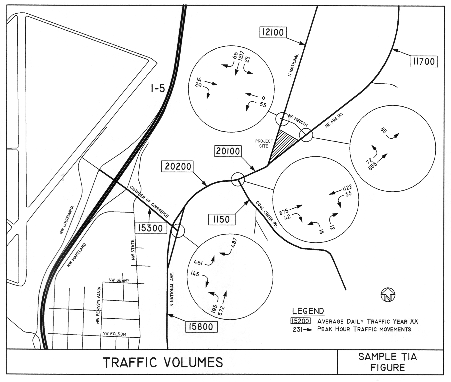
[Ord. 1030B § 1, 2022; Ord. 819B § 13, 2007; Ord. 785B § 14 (2G), 2005.]
Article IV. Storm Drainage and Erosion Control
12.04.340 Storm water management.
A. General. The standards established by this article are intended to represent the minimum standards for the design and construction of storm drainage facilities.
The city of Chehalis storm water management plan and the most recent version of the “Stormwater Management Manual for the Puget Sound Basin” documents are considered a part of this article as well as the city development engineering standards, except as supplemented herein. The storm water management plan sets forth the minimum drainage and erosion control requirements as supplemented herein.
B. Design Standards. The design of storm drainage and/or retention/detention systems will depend on their type and local site conditions. The design elements of storm drainage systems will conform to these standards and follow current design practice as set forth in the city of Chehalis storm water management plan. Properties will not be developed in such a way as to discharge storm water onto adjacent lots.
The general notes that follow will be included in all plans dealing with storm water conveyance and/or detention.
General Notes (Storm Drain Construction)
1. All workmanship and materials will be in accordance with the city of Chehalis development engineering standards and the most recent copy of the State of Washington Standard Specifications for Road, Bridge and Municipal Construction (WSDOT/APWA).
2. Temporary erosion/water pollution measures will be required in accordance with the storm water management plan and Section 1-07.15 of the Standard Specifications.
3. Comply with all other permits and requirements of the city of Chehalis and/or other governing authorities or agencies.
4. A preconstruction meeting will be held with the public works department and the engineering division prior to the start of construction.
5. All storm mains and retention/detention areas will be staked for grade and alignment by an engineering or surveying firm capable of performing such work.
6. Storm drainpipe will meet the following requirements:
a. Plain concrete pipe conforming to the requirements of AASHTO M 86, Class 2.
b. Reinforced concrete pipe conforming to the requirements of AASHTO M 170.
c. PVC pipe conforming to ASTM D3034 SDR 35 or ASTM F794 or ASTM F679 Type 1 with joints and gaskets conforming to ASTM D3212 and ASTM F477.
d. Ductile iron pipe conforming to the requirements of AWWA C151, thickness class as shown on the plans.
e. High-density polyethylene smooth interior pipe conforming to AASHTO M 252 types or AASHTO M 294 Type S, with a gasketed bell and spigot joints.
f. Aluminized steel helical or spiral rib pipe in diameters of 30 inches or greater, with a Manning’s value of 0.020 or less.
7. Special structures, oil/water separators and outlet controls will be installed per plans and manufacturer’s recommendations.
8. Provide traffic control plan(s) as required in accordance with MUTCD to the public works department. Traffic control plans must be approved prior to the start of construction.
9. Call the Utilities Underground Location Center at 1-800-424-5555 a minimum of two business days prior to any excavations.
10. Where connections require “field verifications,” the contractor will expose connection points and verify necessary fittings two business days prior to initiating the work.
11. All storm lines and catchbasins will be high-velocity cleaned and pressure tested in accordance with Divison 7 of the Standard Specifications prior to paving. Hydrant flushing of the lines is not an acceptable cleaning method. Testing of the storm main will include television inspection at the contractor’s expense. The public works department or designated consultant will determine whether the inspection will be performed by the city or by a representative of the contractor under the city’s direction. Testing will take place after all underground utilities are installed and compaction of the roadway subgrade is completed.
12. Fill placement will not be allowed in any open channel used for storm conveyance without written approval from the public works department or designated consultant.
13. Contractors and/or property owners are required to channel water when installing or repairing a driveway. Water may be channeled with a berm or a pipe. Storm water must be diverted to city storm mains when possible.
14. The city must be notified a minimum of two business days in advance of a tap connection to an existing main. A representative from the city must be present at the time of the tap.
15. Prior to backfill, all mains and appurtenances will be inspected and approved by a city inspector. Approval does constitute final acceptance of the sewer line. The contractor will retain responsibility of repairing all deficiencies and failures revealed during required testing for acceptance and throughout the duration of the warranty. It is the contractor’s responsibility to notify the city in advance of all required inspections. Any main or appurtenance backfilled prior to inspection will be reexcavated for inspection at no cost to the city.
Storm water conveyance and detention systems will be designed in accordance with the following design standards table:
|
Hydrologic Model |
|
|
Conveyance Design |
|
|
<50 acres |
Rational Method |
|
>50 <200 acres |
SCS-Based Hydrograph Method |
|
>200 acres |
Continuous Simulation Method |
|
Detention Design |
|
|
<50 acres |
SCS Unit Hydrograph Method with Level Pool Routing |
|
>50 acres |
Continuous Simulation Method |
|
Design Storm Frequency |
|
|
Conveyance |
Capacity to handle: 100-year storm event |
|
Detention |
Prevent peak flow increase: 100-year storm event |
|
|
Evaluation of erosion control: 2-year storm event and 10-year storm event |
|
Design Storm Duration/Distribution |
|
|
Hydrograph Method |
6- and 24-hour durations |
|
SCS Unit Hydrograph Method |
6- and 24-hour durations SCS Type 1A distribution |
|
Rational Method |
Time of concentration Constant rainfall intensity |
C. Conveyance.
1. Pipe. Storm drainpipe within a public right-of-way or easement will be sized to carry the maximum anticipated runoff from the contributing area. The calculations of anticipated runoff and pipe sizing will be developed by a professional engineer licensed in the state of Washington. The developer will provide the calculations and all associated information to the public works department.
2. The minimum main size will be 12-inch diameter; smaller pipe sizes will be considered on a case-by-case basis as approved by the public works department or designated consultant. Lateral lines may be six-inch diameter. The city may require the installation of a larger main if it is determined that a larger size is needed to serve adjacent areas or for future service. The installation of a larger main may allow the developer to seek partial reimbursement through a latecomers agreement (see Article II of this chapter for details).
3. All pipe used for storm mains will comply with one of the following types:
a. Plain concrete pipe conforming to the requirements of AASHTO M 86, Class 2.
b. Reinforced concrete pipe conforming to the requirements of AASHTO M 170.
c. PVC pipe conforming to ASTM D3034 SDR 35 or ASTM F794 or ASTM F679 Type 1 with joints and gaskets conforming to ASTM D3212 and ASTM F477.
d. Ductile iron pipe conforming to the requirements of AWWA C151, thickness class as shown on the plans.
e. High-density polyethylene smooth interior pipe conforming to AASHTO M 252 types or AASHTO M 294 Type S, with a gasketed bell and spigot joints.
f. Aluminized steel helical or spiral rib pipe in diameters of 30 inches or greater, with a Manning’s value of 0.020 or less.
4. Channels. Open vegetated channels may be utilized for storm water conveyance when deemed appropriate by the public works department. Open channels located in a public right-of-way will be sized to carry the maximum anticipated runoff from the contributing area without exceeding the confines of the channel. In addition, when the end of the “new” conveyance system is within 20 feet of another piped drainage system, the “new” system will be extended through the open portion to complete the closed system. Extensions to complete closed drainage systems will only be required along the property where the “new” system originates, unless deemed necessary by the public works department or designated consultant.
5. When the flow of an open channel is interrupted by the construction of a driveway, the entire channel across the property will be enclosed with a piped system, unless deemed impractical by the public works department or designated consultant. However, the culvert under the driveway must be installed to accommodate closure of the ditch in the future. The channel enclosure may necessitate the inclusion of manholes and/or catchbasins. (For manholes please refer to CMC 12.04.580(E) and Standard Drawing Nos. 5-1, 5-2, 5-12, and 5-14.)
D. Catchbasins. Maximum catchbasin spacing will be 300 feet on all street classifications. No surface water will cross any roadway to private property. Additional manholes and/or catchbasins may be required by the city to accommodate the maintenance needs of the storm system.
E. Staking.
1. All surveying and staking will be performed by an engineer or surveyor licensed by the state of Washington and capable of performing such work. Staking will be maintained throughout the construction operation.
2. A preconstruction meeting will be held with the city prior to commencing staking. The city will inspect all construction staking prior to construction.
3. The minimum staking of storm sewer systems will be as follows:
a. Stake centerline alignment every 25 feet with cuts and/or fills to bottom of trench.
b. Stake location of all catchbasins/manholes and other fixtures for grade and alignment.
c. Stake location, size and depth of retention/detention facility.
d. Stake finished grade of catchbasin/manhole rim elevation and invert elevations of all pipes in catchbasins, manholes, and those that daylight.
F. Trench Excavation. See CMC 12.04.510 for requirements regarding trench excavation.
G. Backfilling. See CMC 12.04.530 for requirements regarding backfilling.
H. Street Patching and Restoration. See CMC 12.04.280(O) and (P) for requirements regarding street patching and trench restoration. [Ord. 819B § 13, 2007; Ord. 785B § 14 (3A), 2005.]
12.04.350 Erosion control.
A. General.
1. All projects requiring public works department approval, as defined by these standards, will include erosion control plans if any of the following conditions are met:
a. Proposed land disturbance activities that could cause sediment runoff beyond the project limits.
b. A clearing, filling or grading permit is required.
c. The proposed project could possibly impact a nearby stream, wetland, or body of water.
d. When deemed necessary by another permitting authority.
2. Site work will not commence until all erosion control measures have been set in place in accordance with the approved erosion control plans.
3. The contractor/applicant must ensure that all erosion control measures are properly maintained in accordance with standard industry procedures.
4. The general notes that follow will be included on any plans dealing with erosion control.
General Notes (Erosion Control)
1. Erosion control measures will be in place prior to the beginning of construction. A representative from the city will inspect and approve the erosion control measures prior to the start of construction.
2. Erosion control measures are not limited to the items on this plan. The contractor is responsible for the installation and maintenance of all erosion measures, as required under the most recent version of the Chehalis storm water management plan. Care will be taken to prevent migration of silt and/or polluted runoff to off-site properties.
3. The contractor will make regular surveillance of all erosion control measures. In addition, erosion control will be thoroughly inspected after each rainfall event. The contractor will make all necessary repairs, modifications, and additions as necessary to ensure the proper operation of the erosion control measures. The city may require more frequent inspections of erosion control measures by the contractor should site or weather conditions dictate.
4. During the wet season, November through March, all disturbed soils will be stabilized within 48 hours after land disturbance activities have ceased. Erosion control measures will include, but are not limited to, installation of straw matting, jute matting, straw mulch and/or wood chips, and covering the affected area and spoil piles with plastic sheeting.
5. The contractor will check all seeded or sodded areas regularly to ensure that the vegetative cover is being adequately established. Areas will be repaired, reseeded, and fertilized as required.
6. Tracking of soil off site will not be allowed. If any soil is tracked beyond the limits of the site, it will be removed before the end of that working day. To prevent additional tracking, vehicle tires must be swept or washed prior to leaving the project site.
7. No more than 500 lineal feet (LF) of trench on a downslope of more than five percent will be opened at one time.
8. Excavated material will be placed on the uphill side of trenches.
9. Excavated material will not be placed in established drainage ditches under any circumstances.
10. Trench dewatering devices will be discharged in a manner that will not adversely affect flowing streams, drainage systems, or off-site properties. An established sediment trap will be used as the receiver for all trench dewatering operations.
11. All disturbed areas will be seeded or sodded upon completion of work. The contractor will be responsible to ensure that complete coverage of the disturbed areas is provided and that growth of vegetation is established. Seed and sod applications will be conducted in accordance with the timelines noted in the most recent edition of the WSDOT Standard Specifications.
12. All erosion control will remain in place until such time as the site is adequately stabilized. Prior to removal of erosion control measures, the engineering division will be notified for final inspection and approval.
B. Best Management Practices. Erosion control may include the following:
1. Sedimentation Ponds.
a. Sedimentation ponds are utilized to collect runoff generated on a construction site, thereby allowing sediment to be captured before the runoff leaves the site. Sedimentation pond design will include the following considerations:
i. Computation of the sediment storage volume;
ii. Computation of the settling volume;
iii. Computation of the pond surface area (surface area, in square feet = 1,250 x one-year, 24-hour storm rate, in cfs).
b. Minimum pond dimensions are as follows:
i. Two-foot depth for settling;
ii. Three-foot depth for sediment storage;
iii. Three-to-one ratio side slope.
c. The contractor will inspect sedimentation ponds immediately after each rain event to ensure the integrity of the facility. The contractor will also remove the majority of the sediment collected in the ponds whenever the storage volume is exceeded or the settling volume is infringed upon. In addition, prior to the final completion of the project, ponds will be cleaned out in their entirety.
d. The length/width ratio of the pond will be as large as possible. A 5:1 ratio is the preferred minimum, but exceptions may be granted when deemed appropriate by the public works department or designated consultant. The pond will be divided into a series of at least two separate chambers. Perforated pipe risers will be used to convey water between the chambers and at the outlet.
2. Interceptor Channels. Interceptor channels are used to capture runoff generated on a construction site before it can leave the project limits. The channel is often used in combination with a sedimentation pond. The channel is typically grass-lined and runs along the perimeter of the site. The grass must be established prior to the start of construction. Therefore, sod is often used to establish the vegetated surface of the channel. Upon completion of the project, the sod can be removed and reused if the ditch is filled in and restored with a suitable and stable cover material.
3. Sediment Barriers. Sediment barriers are filtering devices that are run along the perimeter of a site to capture sediment while allowing runoff water to continue along its natural path. Silt fencing and hay bales are common examples of sediment barriers.
Regular removal of sediment is required to ensure that the barriers function properly. In addition, the structural integrity of the barriers must be maintained at all times. Barriers will be installed, inspected and repaired in accordance with the details and requirements included in these standards.
4. Stabilized Construction Entrance. A stabilized construction entrance is a rocked access point to a construction site. The entrance reduces material carried from the site onto the public right-of-way.
Construction entrances must be cleared of mud and debris regularly to ensure that materials are not being tracked from the construction site onto the right-of-way and beyond. The contractor is responsible for all required maintenance of entrances.
5. Detention/Retention Facilities. No retention/detention facility will be located in an area that is used to satisfy an open space requirement unless it enhances a recreational amenity. Use of designated open space areas for storm water detention/retention and infiltration must satisfy all conditions of the city of Chehalis for usability, landscape conformity and ease of access. The city will make the final determination whether or not the proposed storm water facilities are compatible with and satisfy the intent of an open space.
The primary purpose of a consolidated open space is to provide usable area for recreation activities, buffer zones, and green belt areas, and must be designed for this intent. Any use of this area for storm water detention/retention must clearly be subordinate to and not detract from open space uses. The usable open space will be predominantly flat and in no case exceed 4:1 where drainage facilities are present. A minimum of 50 percent of the linear slope length will not exceed 7:1.
The public works department or designated consultant will review the use of commercial parking lots for storm water detention on a case-by-case basis. The detention area will be situated away from areas of pedestrian movement. The maximum depth of water in parking lot storage will be limited to 12 inches. [Ord. 819B § 13, 2007; Ord. 785B § 14 (3B), 2005.]
Article V. Water
12.04.360 General.
Any extension of the Chehalis water system must be approved by the department of public works and conform to the department of health, the city of Chehalis water system plan, and Chehalis police department and fire department requirements.
In designing and planning for any development, it is the developer’s responsibility to determine that adequate water for both domestic use and fire protection is attainable. Proposed plans must show how water will be supplied and whether adequate water pressure and volume will be maintained in case of fire. An analysis of the system may be required if it appears that the system might be inadequate.
Anyone desiring to extend or connect to the city water system must contact the engineering division for a water/sewer/storm water application form. After the completed application is returned to the public works department, along with any other information that may be required or requested, staff will determine the costs to connect to city utilities. Extension of or connection to city water lines outside of the Chehalis urban growth area (UGA) is permitted only when a demonstrated public health risk exists and has been identified in writing by an appropriate health agency.
Prior to the issuance of a water meter for development projects, all public works improvements must be completed and approved, including granting of right-of-way or easements, submission and acceptance of as-built drawings, and all applicable fees must be paid.
Building permits for new construction of single-family subdivisions will not be issued without final approval of the public works director. For commercial projects, building permits may be issued upon completion and acceptance of the required fire protection facilities. A construction bond, in accordance with CMC 12.04.190, will be required for the remaining improvements. A certificate of occupancy will not be issued until final public works approval is given for all improvements. [Ord. 785B § 14 (4.01), 2005; Ord. 767B, 2004; Ord. 766B, 2004.]
12.04.370 Design standards.
A. The design of any water extension/connection shall conform to these standards and all other applicable standards. The layout of extensions shall be extended to and through the property frontage to be developed to provide for continuation and/or looping of the existing system. The public works department and/or the engineering division has the authority to apply or necessitate items not covered or mentioned in this article.
B. The general notes that follow must be included on all plans dealing with the city of Chehalis water system.
General Notes (Water Main Installation)
1. All workmanship and material will be in accordance with city of Chehalis standards and the most recent copy of the WSDOT/APWA Standard Specifications for Road, Bridge and Municipal Construction, American Water Works Association (AWWA) Standards and ANSI/NSF Standard 60 or 61.
2. A preconstruction meeting will be held with the public works department and the engineering division prior to the start of construction.
3. All water mains will be ductile iron cement mortar lined thickness Class 52.
4. Gate valves will be resilient wedge, NRS (nonrising stem) with O-ring seals. Valve ends will be mechanical joint or ANSI flanges. Valves will conform to AWWA 509-80. Valves will be Mueller, M&H, Kennedy, Clow R/W or American Flow Control Series 2500. Existing valves and all valves installed directly to and connected to a portion of the active water system are to be operated by city employees only.
5. Fire hydrants will be Mueller Centurion A-423, M&H Reliant Style 129, Clow Medallion, or Kennedy Guardian K81D, Waterous Pacer Model WB-67-250 or AVK 2780. Hydrants will be installed in accordance with the most recent version of the International Fire Code. Hydrants will be bagged and the connecting gate valves left closed until the system has been approved. Hydrants must be painted with sunburst yellow high-grade enamel after installation.
6. All lines will be chlorinated and tested in conformance with the above-referenced specifications (see Note 1).
7. All pipes and services will be installed with continuous tracer tape placed 12 to 18 inches under the proposed finished subgrade. The marker will be of plastic, nonbiodegradable, metal core, or backing marked “WATER” that can be detected by a standard metal detector. Tape will be Terra Tape “D” or approved equal. In addition to tracer tape, toning wire will be installed over all pipe and services. Toning wire will be UL listed, type UF, 14-gauge solid coated copper wire, taped to the top of the pipe to prevent movement during backfilling and laid loose enough to prevent stretching and damage before being brought up and tied off at the valve operating nut or valve box. If the operating nut is not easily accessible from the ground surface, the copper wire will be tied off at the valve box in such a way that the wire is easily accessible from the ground surface. Two feet of slack will be provided to allow for connection to the locator.
A one-pound magnesium anode will be buried with the pipe every 1,000 linear feet maximum for cathodic protection of the toning wire. Toning wire splices and connections to anodes will join wires both mechanically and electrically and will employ epoxy resin or heat-shrink tape insulation. Toning wire will be tested prior to acceptance of the pipe system. A written notice from the contractor to the city must be received two business days prior to when testing is required.
8. The contractor will provide traffic control plan(s) as required in accordance with MUTCD.
9. All water mains will be staked for grades and alignment by an engineering or surveying firm capable of performing such work. Staking will be maintained throughout construction.
10. All service line and water valve locations will be marked on the face of the adjacent curb with a “W” or “WV” embossed one-fourth inch into the concrete.
11. All water system connections serving buildings or properties with domestic potable water, fire sprinkler or irrigation systems will comply with the minimum backflow prevention requirements established by the Department of Health (DOH) and the city of Chehalis cross-connection control program.
12. Call Utilities Underground Location Center at 1-800-424-5555 a minimum of two business days prior to any excavations.
13. The city will be notified five business days prior to scheduling a water system shutdown. The city’s water division will perform all water system shutdowns. When connections require “field verification,” connection points will be exposed by the contractor and fittings verified by the city two business days prior to the distribution of shutdown notices. Customers involved with or affected by water service interruptions will be notified at least 48 hours in advance. Shutdowns will not be permitted on Fridays, weekends, or holidays without written authorization from the director of public works.
14. When connecting to an existing water line where a new valve is not to be installed, the existing valve must be pressure tested to these standards by the contractor prior to connection. If an existing valve fails to pass the test, the contractor will make the necessary additional provisions to test the new line prior to connecting to the existing system or will install a new valve. New lines will not be connected to the existing system until all required tests have been passed.
[Ord. 858B § 2, 2010; Ord. 785B § 14 (4.02), 2005.]
12.04.380 Water main.
A. General. Water mains will be sized to provide adequate domestic water plus fire flows at the required residual pressure. Fire flow requirements will be determined by the Chehalis fire department. However, the quantity of water required will in no case be less than 1,000 gpm at 20 psi residual pressure in single-family and/or duplex residential areas, or less than 1,500 gpm at 20 psi residual pressure in multifamily residential areas, commercial areas and/or industrial areas.
The minimum water main size will be six inches in diameter where looped. Dead-end mains will be a minimum of eight inches in diameter. All mains that may be extended or looped must end with an approved flanged gate valve and blind flange. A straddle block will be installed at a point along the last length of pipe preceding the valve, in lieu of a thrust block at the end.
Larger-sized mains may be required in specific areas identified in the Chehalis water system plan. The city may also require the installation of larger mains if determined necessary to meet fire protection needs, domestic requirements and/or for future service needs (see CMC 12.04.130, Latecomers agreements).
B. Piping. All pipe for water mains will have flexible gasketed joints and will comply with the following specifications:
Ductile iron pipe will conform to AWWA C151 Class 52 and will have a cement mortar lining conforming to AWWA C104. All pipes will be joined using nonrestrained joints that will be rubber gaskets, push-on type or mechanical joint, conforming to AWWA C111.
C. Fittings. All fittings will be ductile iron compact fittings conforming to AWWA C153 or AWWA C110 or C111. All fittings will be cement mortar lined conforming to AWWA C104. Plain-end fittings will be ductile iron if mechanical joint retainer glands are installed on the plain ends. All fittings will be connected by flanges or mechanical joints. The city shall require the use of MEGALUG retainers for a water line installation, as necessary.
D. Pipe Installation. All pipe and services will be installed as directed in note 7 of the general notes in CMC 12.04.370.
E. Cover Required. The minimum cover for all water mains from top of pipe to finished grade will be 30 inches for ductile iron pipe unless otherwise approved.
F. Connection to Existing Water Mains. The developer’s engineer will be responsible for determining the scope of work for connection to existing water mains. A minimum of five business days’ advance notice to the water division is needed to schedule shutdowns. However, shutdowns cannot be scheduled until a water/sewer/storm water application has been approved and all applicable fees have been paid in full. The city of Chehalis water division will be consulted regarding fittings or couplings required. It will be the contractor’s responsibility to verify the location and depth of the existing main and the fittings required to make the connections to the existing main. All excavation, connections, piping, tapping valve fittings, services, anchors, blocking, bedding, backfill, compaction, restoration and other labor and materials required will be furnished and placed by the contractor. The tapping of an existing water main will be done in the presence of a water division representative. The water division will be given two business days’ advance notice of a water main tap and they will perform all shutdowns on existing mains. [Ord. 785B § 14 (4.03), 2005; Ord. 767B, 2004.]
12.04.390 Service interruption.
The contractor will give the public works department a minimum of five business days’ advance notice of any planned connection to an existing pipeline. This includes all cut-ins and live taps. Notice is required so disruptions to existing services can be scheduled and affected customers notified. The contractor will make every effort to schedule water main construction with minimum disruption of water service. The contractor is responsible for ensuring that the excavation and shoring procedures comply with L&I standards for worker safety. If these procedures are not followed, the connection will not be performed. [Ord. 785B § 14 (4.04), 2005.]
12.04.400 Hydrants.
A. The lead from the service main to the fire hydrant will be ductile iron cement mortar lined Class 52, no less than six inches in diameter. A gate valve will be installed a minimum of three feet from the hydrant, unless otherwise approved.
B. Fire hydrants will have two two-and-one-half-inch outlets with National Standard threads and one four-inch pumper port outlet with Pacific Coast threads (male threaded 4.72-inch diameter). The pumper port will be fitted with a five-inch quick connect Storz adapter with a Pacific Coast thread hydrant connection (female threaded four-and-three-fourths-inch diameter). The Storz adapter will include a cap. The hydrant valve opening will be five-and-one-fourth-inch diameter. The hydrant will have a positive and automatic barrel drain and will be of the “safety” or breakaway style.
Hydrants will be Mueller Centurion A-423, M&H Reliant Style 129, Clow Medallion or Kennedy Guardian K81D, Waterous Pacer Model WB-67-250 or AVK 2780. Alternate hydrant styles and manufacturers will be considered on a case-by-case basis and must be approved by the director of public works. All hydrants will be bagged and the connecting gate valves will remain closed until the system is tested and approved. Developments being served by existing hydrants will be required to upgrade to these standards and use the same type of hydrant throughout the development. Hydrants will be painted with sunburst yellow high-grade enamel after installation.
C. The department of public works and Chehalis fire department will work together to determine the required hydrant spacing for installation. All hydrants will be installed and placed in a manner that provides accessibility to the fire department and their equipment as determined by both departments.
Unless otherwise required by the public works department, the following guidelines will apply for hydrant number and location:
1. At least one hydrant will be installed at all intersections.
2. Hydrant spacing of 300 feet will be required in all areas except single-family and duplex residential areas.
3. Hydrant spacing of 500 feet will be required for single-family and duplex residential areas.
4. The spacing distance for hydrants will be measured along the frontage street(s) and/or accessible side street(s) only. When determining the sufficiency of existing hydrants related to hydrant placement and spacing, hydrants located behind or on parallel streets or alleys, or hydrants with flows less than the minimum fire flows listed in CMC 12.04.380(A), will not be considered.
5. When any portion of a proposed building is in excess of 150 feet from a water supply on a public street or right-of-way, privately owned on-site hydrants will be required. Such hydrants will be located per the Chehalis fire department and the International Fire Code. The hydrants will be privately maintained and will include the appropriate metering and backflow prevention, as noted in these standards. A proposed maintenance schedule will be submitted to the city for review prior to final approval of the engineering plans.
D. Fire hydrants will be installed as detailed in Standard Drawing 4-8.
E. For requirements regarding use, size and location of a fire department connection (FDC) and/or post indicator valve, contact the fire department. Location of the FDC will be shown on all water plans.
F. When necessary, the public works department may require hydrants to be protected by two or more posts, four-inch diameter by five feet high, made of either reinforced concrete or steel.
G. Fire hydrants must be installed, tested, and accepted prior to the issuance of a certificate of occupancy. [Ord. 785B § 14 (4.05), 2005; Ord. 767B, 2004.]
12.04.410 Valves.
All valves and fittings will be ductile iron with ANSI flanges or mechanical joint ends. All existing valves are to be operated by city employees only.
Valves will be installed in the distribution system at sufficient intervals to facilitate system repair and maintenance, but in no case will there be less than one valve every 1,000 feet. Generally, there will be two valves on each tee and three valves on each cross. Specific requirements for valve spacing will be made at the plan review stage.
A. Gate valves will be used on all two- to 12-inch lines. The design, materials and workmanship of all gate valves will conform to the most recent revision of AWWA C509-87. Gate valves will be resilient wedge nonrising stem (NRS) with two internal O-ring stem seals. Gate valves will be Mueller, M&H, Kennedy, Clow R/W or Waterous Series 500.
B. Butterfly valves will be used on all lines 14 inches and larger. Butterfly valves will conform to AWWA C504-87, Class 150B, with cast iron short body and O-ring stem seals. Butterfly valves will be Mueller, Linseal III, Kennedy, Pratt Groundhog, or Allis Chalmers.
C. Valve Box. All valves will have a standard Olympic Foundry 910 or 940 water valve box as determined by the water division. If the city approves or requires the use of an Olympic 910 valve box, it will be set to grade with a six-inch ASTM 3034 SDR 35 PVC riser from valve to approximately six inches from the valve box top. If valves are not set in a paved area, a three-by-three-foot concrete pad four inches thick will be set around each valve box at finished grade. An Olympic Foundry 940 valve box will be required for all locations of heavy traffic. In areas where the valve box is on the shoulder of the road, the ditch and shoulder will be graded before placing an asphalt or concrete pad. Valve box lids will be ductile iron, anti-kickout, and marked “WATER” (see Standard Drawing 4-12). All valve locations will be marked on the face of the adjacent curb with a “WV” embossed one-fourth inch into the concrete. [Ord. 785B § 14 (4.06), 2005.]
12.04.420 Casing.
Steel casing pipe will be schedule 20 steel or equal. Pipe spacers will have eight-inch runners. Casting pipe and spacers will be sized for pipe being installed with a minimum of three spacers per section of pipe. The casing pipe will then be sand-packed and sealed in accordance with the spacer manufacturer’s recommendations. [Ord. 785B § 14 (4.07), 2005.]
12.04.430 Air and vacuum release valve.
Air and vacuum release valves (ARV) will be APCO combination air release valves. Installation will be as shown on Standard Drawing 4-9.
The installation will be set at the high point of the line when required. Where possible, pipes are to be graded to prevent the need for an air release valve. Air release valves may not be required when services are in the vicinity; however, the final determination will be made by the public works department. [Ord. 785B § 14 (4.08), 2005.]
12.04.440 Blowoff assembly.
If a fire hydrant is not located at the end of a dead-end main, a blowoff assembly will be required. On water mains that may be extended in the future, the valve that operates the blowoff assembly will be the same size as the main and provided with a saddle block along the last length of the pipe preceding the valve, in lieu of a thrust block at the end. The working pressure rating for blowoff assemblies will be a minimum of 200 psi. Installation will be as shown on Standard Drawing 4-10. [Ord. 785B § 14 (4.09), 2005.]
12.04.450 Backflow prevention.
All water system connections providing buildings or properties with domestic potable water, fire suppression or irrigation systems will comply with the backflow prevention requirements as established by the Department of Health (DOH), WAC and the city of Chehalis cross-connection control program.
Having an approved backflow assembly(s) installed is necessary to protect the city water system and all users from any possible contamination. All backflow assemblies installed will be of a type and model preapproved by the DOH or the city. No cross-connections will be created, installed, used, or maintained within the city of Chehalis water system. A list of approved testers may be obtained from the Washington Environmental Training Resource Center (WETRC) located in Auburn, Washington.
In-premises cross-connections must have an approved backflow assembly(s) in place in accordance with the Uniform Plumbing Code (UPC). The city may require additional in-premises and/or premises protection in accordance with the DOH and the city of Chehalis cross-connection control plan when health hazards are determined to exist.
All assemblies must be installed in accordance with the most recent versions of the city of Chehalis cross-connection control program, the DOH, UPC, and the PNWS/AWWA Cross-Connection Control Manual. In addition, all assemblies must be inspected and approved by the city’s cross-connection specialist (CCS). The CCS may also conduct an on-site inspection of new and/or existing backflow assemblies during testing. The city will release or issue a certificate of occupancy only after all backflow assemblies have passed a certified test.
Any person violating any provision of the city of Chehalis cross-connection control plan will be subject to penalties as stated under CMC 13.04.070(G) and (H).
A. Backflow Assemblies. The definitions, abbreviations and acronyms relating to cross-connections frequently used in cross-connection control are found in the Washington State Department of Health Water System Design Manual as applies to “Group A” public water systems. Accepted backflow prevention assemblies are RPBA, RPDA, DCVA, DCDA, PVBA or SVBA of a make, model, and size that has been approved by the DOH. Assemblies on the current approved backflow prevention assemblies list developed by the University of Southern California Foundation for Cross-Connection Control and Hydraulic Research are also approved.
B. Installation Requirements. Backflow prevention assemblies used for premises isolation will be installed at the expense of the user, downstream from the city’s water metering device, but within six feet of the meter box or before any other use connection, to protect the water distribution system from any potential hazard, as determined by the city. All assemblies must be installed in accordance with the most current versions of the city of Chehalis cross-connection control plan, DOH requirements, UPC, and the PNWS/AWWA Cross-Connection Control Manual.
In-premises installation of backflow assemblies can be installed only with written permission by the city’s CCS or may be mandated along with premises isolation when high health hazards are determined to exist by the CCS. All backflow assemblies (premises or in-premises) must be readily accessible to city personnel during regular working hours of 8:00 a.m. to 4:30 p.m. If there is a change of ownership of an in-premises backflow assembly and/or at any time all requirements are not met, the city of Chehalis has the right to enforce premises isolation and will follow the procedures established in the city of Chehalis cross-connection control plan, Section 6 (a – f). The city of Chehalis must be notified within two business days of the completion of a backflow assembly installation. Upon notification, the city’s CCS will then inspect the installation to determine compliance with all applicable requirements.
All backflow assembly installations are also required to be tested by a Washington State DOH-certified backflow assembly tester (BAT) with an annual certificate of accuracy for their testing equipment on file with the city. The test results must be sent to the city showing the backflow assembly having successfully passed the certified test. The property owner must schedule a backflow test annually.
C. Costs of Compliance. All costs associated with purchase, installation, inspections, testing, replacement, maintenance, parts and repairs of a backflow assembly are the responsibility of the property owner/user.
D. Termination of Services. Failure on the part of any customer to correct all cross-connections in accordance with these standards is sufficient cause for the immediate discontinuance of public water service to the premises. [Ord. 785B § 14 (4.10), 2005.]
12.04.460 Service connection.
A. All service connection sizes used for new development will be determined by industry standards and approved by the public works department or designated consultant and installed by the developer at the time of mainline construction. After the lines have been constructed, tested and approved, the owner may request a water meter. The city will install a water meter only after a water/sewer/storm application has been completed, all applicable fees paid and the system inspected and approved. With the placement of one-and-one-half-inch or two-inch meter setters (Standard Drawing No. 4-3), the contractor shall install the meter at the time the setter is put in place. The contractor shall contact the city two business days prior to the installation of the setter and coordinate the delivery of the meter with the installation of the setter. Meter and gasket will be supplied by the city. The city will lock off the setter after the contractor has installed the meter.
B. When water is desired for a parcel fronting an existing main but not served by an existing setter, a water/sewer/storm application must be completed and returned to the city. Upon approval of the application and payment of all applicable fees, the city will tap the main and install the meter, box, and setter.
C. Service lines shall be CTS (copper tube size) class 250 high density polyethylene pipe and must meet ASTM D-2737, ASTM D-3350, AWWA C-651, AWWA C-901 specifications. All connections will be of Ford, McDonald or Mueller 110 compression connection fittings. Service lines will be installed a minimum of 22.5 degrees off the main. Tracer tape will be installed over all service lines. Service saddles will be ductile iron with double stainless-steel traps. All clamps will have rubber gasket and iron pipe threaded inlet, and iron pipe threaded or approved compression outlet connections. Corporation stops will be all U.S. brass and will be Ford, Mueller, or A.Y. McDonald with iron pipe (IP) threads with tapping saddles and CC threads on direct taps conforming to AWWA C800.
D. Master meters will not be allowed for service to more than one building. An approved backflow prevention system must be installed in conjunction with any master meter, in accordance with the requirements outlined in this article. [Ord. 1070B § 1, 2023; Ord. 819B § 13, 2007; Ord. 785B § 14 (4.11), 2005.]
12.04.470 Marking service lines.
The location of all service lines will be marked on the face or top of the cement concrete curb with a “W” embossed one-fourth inch into the concrete. [Ord. 785B § 14 (4.12), 2005.]
12.04.480 Water main/sanitary sewer crossings.
The contractor will maintain a minimum of 18 inches of vertical separation between sanitary sewers and water mains – with the water mains being at the higher elevation. If the minimum vertical separation cannot be met, the standards for water/sewer separation from the DOE Guidelines as shown in this section will apply.
The longest standard length of water pipe will be installed so that the joints will fall equidistant from any sewer crossing. In cases where minimum separation cannot be maintained, it may be necessary to utilize water main-rated pipe for the sewer line, or to encase the water pipe and/or sewer line in pipe or concrete. No concrete will be installed unless specifically directed by the public works department or designated consultant.
Water/Sewer Separation Detail Department of Ecology Guidelines
Figure 1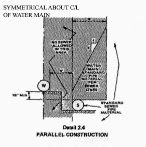
|
Type of Pipe |
AWWA (ASTM) Standard |
||
|---|---|---|---|
|
Pipe |
Joint |
Fittings |
|
|
Ductile Iron |
C151 and C104 |
C111 |
C110 |
|
Asbestos-Cement |
C400 (Type II) Class 200 |
(D1869) |
C110 |
|
Polyvinyl-Chloride |
C900 |
(D3139 and F477) |
C110 |
|
Concrete Cylinder |
|
|
C303 |
[Ord. 819B § 13, 2007; Ord. 785B § 14 (4.13), 2005.]
12.04.490 Irrigation.
All irrigation systems will be installed with a backflow prevention assembly approved by the Department of Health or the city of Chehalis. Irrigation sprinklers will be situated so as to not wet any public street or sidewalk. [Ord. 785B § 14 (4.14), 2005.]
12.04.500 Staking.
All surveying and staking will be performed by an engineering or surveying firm licensed by the state of Washington and capable of performing such work. A preconstruction meeting will be held with the city prior to commencing staking and all staking will be inspected by the city prior to construction and maintained throughout construction.
The minimum staking of water lines will be as follows:
A. Stake centerline alignment every 25 feet (50 feet in tangent sections), with cuts and/or fills to bottom of trench maintaining the minimum required depth of cover over pipe. Centerline cuts are not required when road grade is to finished subgrade elevation.
B. Stake location of all fire hydrants, hydrant flange elevations, tees, water meters, setters and other fixtures with cut or fill to finished grade. [Ord. 785B § 14 (4.15), 2005.]
12.04.510 Trench excavation.
A. Clearing and grubbing, when required, will be performed within the easement or public right-of-way as permitted by the city and/or governing agencies. All debris resulting from clearing and grubbing must be disposed of by the owner or contractor in accordance with the terms of the applicable permits.
B. Trenches will be excavated to the line and depth designated by the city to provide a minimum of 30 inches of cover over the pipe and, to the extent practical, a maximum of 42 inches of cover over the pipe. Except for unusual circumstances where approved by the city, the trench sides will be excavated vertically and the trench width will be excavated only to such widths as are necessary for adequate working space as allowed by the governing agency. The trench will be kept free from water until pipe assembly is complete. Surface water will be diverted so as not to enter the trench. The owner will maintain sufficient pumping equipment on the job to ensure that these provisions are carried out.
C. The contractor will perform excavation of every description and of whatever substance encountered including boulders, rocks, roots and other obstructions. All material will be entirely removed or cut out to the width of the trench and to a depth six inches below water main grade. Where materials are removed from below water main grade, the trench will be backfilled to grade with thoroughly compacted material that is satisfactory to the city.
Pipe placed in the trench will be sealed with a watertight plug at the end of each day. More frequent use of a watertight plug may be required at the discretion of the city.
D. Trenching and shoring operations will not proceed more than 100 feet in advance of pipe laying without approval of the city, and will be in conformance with the Washington Industrial Safety and Health Administration (WISHA) and Office of Safety and Health Administration (OSHA) Safety Standards. The contractor will also maintain the presence of a “competent person” as defined by the Washington State Department of Labor and Industries when any trench excavation and backfill work is being done at the project site.
E. The bottom of the trench will be finished to grade with hand tools in such a manner that the pipe will have bearing along the entire length of the barrel. The bell holes will be excavated with hand tools to sufficient size to make up the joint. [Ord. 785B § 14 (4.16), 2005.]
12.04.520 Thrust blocking.
Location of thrust blocking will be shown on plans. Thrust block concrete will be Class B poured against undisturbed earth. A plastic barrier will be placed between all thrust blocks and fittings. The city shall require the use of MEGALUG restrainers, Romac retainers or restraining rods in lieu of and/or in conjunction with thrust blocking. See Standard Drawings 4-13 and 4-14 for thrust block locations and calculations. [Ord. 785B § 14 (4.17), 2005.]
12.04.530 Backfilling.
Backfilling will not commence until the pipe installation has been inspected and approved by a city inspector. Backfilling and surface restoration will closely follow installation of pipe so that not more than 100 feet is left exposed during construction hours without approval of the city.
Selected bedding material conforming to WSDOT/APWA Standard Specifications will be placed and compacted around and under the water mains by hand tools to a height of six inches above the top of the water main. The remaining backfill will be compacted to 95 percent of the maximum density in traveled areas, 90 percent outside traveled areas. The city will have the discretion of requiring the use of control density fill (CDF) for backfill material for road crossings.
Where governmental agencies other than the city have jurisdictions over roadways, the backfill and compaction will be done to the satisfaction of the agency having jurisdiction, but in no case will the backfilling or compaction be to a lower standard than that of the city. If suitable backfill material, as determined by the city, is not available from trenching operations, the city may require the placement of bedding and/or a gravel base conforming to the current WSDOT/APWA Standard Specifications. [Ord. 785B § 14 (4.18), 2005.]
12.04.540 Street patching and restoration.
See CMC 12.04.280(O) and (P) for requirements regarding street patching and trench restoration. [Ord. 785B § 14 (4.19), 2005.]
12.04.550 Hydrostatic tests.
Prior to the acceptance of work, installation will be subject to a hydrostatic pressure test by the contractor. All pumps, gauges, plugs, saddles, corporation stops, miscellaneous hose and piping, and measuring equipment necessary for performing the test will be furnished and operated by the contractor. Tests will be conducted only after all connections along the section to be tested have been made and the roadway section is constructed to subgrade.
The section of water main being tested will be filled with water and allowed to stand under pressure for a sufficient length of time to allow air to escape and the pipe lining to absorb water. The contractor will be responsible for all costs, labor and materials associated with the testing of the line. The contractor will pay for all water needed for testing at the current rate charged by the city.
The test will be accomplished by pumping the main up to a pressure 150 psi above normal operating pressures but in no case will the test pressure be less than 200 psi. After reaching the test pressure, the pump will be stopped for 15 minutes and then the pressure brought back up to the test pressure again. The quantity of water used to restore the pressure will be accurately determined by pumping through a positive displacement water meter. The meter will be approved by the public works department prior to testing.
Acceptability of the test will be determined by using the following formula:
|
L = |
N x D x (P^1/2) |
|
|
7400 |
|
L = allowable leakage, gallons per hour (gph) |
|
|
N = number of joints in the length of pipeline tested |
|
|
D = nominal diameter of pipe, inches |
|
|
P = average test pressure during the leakage test, psi |
|
If the water used to restore the pressure in the system is greater than the allowable leakage determined by the formula, the main will be considered to have failed. There will not be any appreciable or abrupt loss in pressure during the 15-minute test period. Any significant loss will also be grounds for a nonpassing test. Should the tested section fail to pass the pressure test as specified, the contractor will, at no expense to the city, locate and repair the defects and then retest the pipeline. All tests will be made with the hydrant auxiliary gate valves open and pressure against the hydrant valve. After the test has been completed, each gate valve will be tested individually by closing each in turn and relieving the pressure beyond. This test will be acceptable if there is no immediate loss of pressure on the gauge when the pressure comes against the valve being checked. The contractor will verify that the pressure across the valve does not exceed the rated working pressure of the valve.
Sections to be tested will normally be limited to 1,500 feet. The public works department or designated consultant may require that the first section of the pipe installed by the contractor, not less than 1,000 feet in length, be tested in order to qualify the crew and the material. Pipe installation will not be continued for more than an additional 1,000 feet until the first section has been successfully tested.
Prior to calling a city inspector to witness the pressure test, the contractor will have all equipment ready for operation and have successfully performed the test to ensure that the pipe is in satisfactory condition.
Defective material or workmanship discovered during a hydrostatic field test will be replaced by the contractor at no expense to the city. Whenever it is necessary to replace defective material or correct workmanship, the hydrostatic test will be rerun at the contractor’s expense until a satisfactory test is obtained. Test pressure will be maintained while the installation is inspected by the city. See CMC 12.04.450 for testing responsibilities related to backflow prevention devices. [Ord. 819B § 13, 2007; Ord. 785B § 14 (4.20), 2005.]
12.04.560 Sterilization and flushing.
Sterilization of water mains will be accomplished by the contractor in accordance with the requirements of the Washington State Department of Health, AWWA Standards and in a manner approved by the city. At no time will chlorinated water from a new main be flushed into a body of water, including lakes, rivers, streams, drainage ways, and all waters where fish or other natural water life can be expected. Any discharge into a city sewer system must be approved in advance and in writing by the wastewater superintendent.
When the proper chlorine concentration has been established throughout the line, the valves will be closed and the line left undisturbed for 24 hours. The line will then be thoroughly flushed and water samples taken by the city at least 24 hours after flushing and disinfecting. Sampling collection should be scheduled with the engineering division at least two business days in advance. Should the initial chlorine treatment result in an unsatisfactory bacteriological test, the procedure must be repeated until satisfactory results are obtained. The contractor will be responsible for all costs if retesting becomes necessary. Samples can only be taken on Mondays and Tuesdays. Testing and sampling will take place after all underground utilities are installed and compaction of the backfill within the roadway section is complete. [Ord. 785B § 14 (4.21), 2005.]
Article VI. Sanitary Sewer
12.04.570 General considerations.
A. General. “Sanitary sewerage” refers to wastewater derived from domestic, commercial and industrial pretreated waste to which storm, surface, and ground water are not intentionally admitted. Pretreatment will follow all the requirements as set forth by city ordinances and public works departmental policies.
Any extension of the city of Chehalis sanitary sewer system must be approved by the public works department and must be consistent with the city of Chehalis comprehensive sewer plan, city of Chehalis general sewer plan, Department of Ecology, and Department of Health requirements.
Within the corporate city limits, where public sewer is available it must be used. Connection is not required; provided, that the sewage from the structure originates more than 200 feet from the public sewer, except in the case of private residential or commercial developments where the developed property abuts a right-of-way in which a public sewer is located or where a service connection is otherwise provided. In this case, connection of all structures generating sewage will be required to connect to the public sewer regardless of distance.
Anyone who wishes to extend or connect to the city sewer system will contact the public works department for a water/sewer/storm application. If a sewer line extension is being requested, a written request that specifically lists and details the line extension must be submitted to the public works department. The extension will be extended to and through the extremes of the property frontage being developed for future development; provided, that further utility extension is possible, as determined by the public works director. After the water/sewer/storm application is approved, along with any other information as may be required or requested, city staff will determine estimated fees.
See CMC 12.04.060 for definitions of specific sewers. Maintenance of the building sewer will be the responsibility of the property owner, while the remaining sewer lateral will be the city’s responsibility.
B. Marking Side Sewers. The location of all side sewers will be marked on the face or top of the cement concrete curb with an “S” embossed one-fourth inch into concrete.
C. Sanitary Sewer/Water Main Crossings. See CMC 12.04.480 for requirements regarding sewer and water separation.
D. Staking.
1. All surveying and staking will be performed by an engineering or surveying firm licensed by the state of Washington and possessing the appropriate business license(s) to perform such work.
2. A preconstruction meeting will be held with the public works department and the engineering division prior to commencing staking. All construction staking will be inspected by the city prior to construction. Staking will be maintained throughout construction.
3. The minimum staking of sewer lines will be as follows:
a. Centerline alignment must be staked with cuts and/or fills to flow at 25 feet and 50 feet from each manhole or structure and every 50 feet thereafter, unless more frequent staking is required for construction at the discretion of a city representative.
b. Manholes must be staked with hubs to include invert elevations of all pipes and top of rim elevations to finished grade.
c. Location of valves, fixtures and septic tank will be staked for force mains and STEP systems.
E. Trench Excavation. See CMC 12.04.510 for requirements regarding trench excavation.
F. Backfilling. See CMC 12.04.530 for requirements regarding backfilling.
G. Street Patching and Restoration. See CMC 12.04.280(O) and (P) for requirements regarding street patching and trench restoration.
H. Testing. Prior to acceptance and approval of construction, the following tests will apply to each type of construction:
1. Gravity Sewer.
a. After the pipes have been cleaned, and prior to acceptance of the project, the gravity sewer line will be subject to a low pressure air test per WSDOT/APWA standards. The contractor will furnish all equipment and personnel for conducting the test under the observation of a city inspector. The testing equipment will be subject to approval of the public works department or designated consultant.
Prior to calling a city inspector to witness the test, the contractor will have all equipment ready and have successfully performed the test. The air test for acceptance will be made after the trench is backfilled and compacted and the roadway section is completed to subgrade.
All wyes, tees, and ends of side sewer stubs will be plugged with flexible joint caps, or acceptable alternates, securely fastened to withstand the internal test pressures. Such plugs or caps will be readily removable and their removal will provide an opening suitable for a lateral connection or extension that conforms to these standards.
b. Testing of the sewer main will include a television inspection by the contractor, conducted under the direct supervision of an engineering inspector. Sewer laterals that cannot be otherwise checked for grade may be required to be televised using the same procedures as a sewer main, as determined by the public works director. Failure to have a city representative present will invalidate the test and the test will be repeated at the contractor’s expense. Television inspections will be done after the air test has passed, the manhole has been channeled and before the roadway is paved. Immediately prior to the television inspection, enough water will be run down the line to come out the lower manhole. A sediment trap will be installed in the downstream manhole prior to flushing the line. The sediment trap and all the material it collects will be removed before the line is placed into service. A copy of the video and a written report will be submitted to the engineering division. Acceptance of the line will be made after the tape has been reviewed and approved by a city inspector. Any connection to an existing system will need to be televised as well.
The city may televise the new sewer line during periods of high ground water within the first year after acceptance of the line. Any conditions resulting in inflow and infiltration (I&I) will be considered a system failure that will be repaired by and at the expense of the contractor.
c. A vacuum test of all manholes is required prior to acceptance. The structure will be tested in accordance with ASTM C1244-93. This test method covers procedures for testing cast-in-place or pre-cast concrete manhole sections, using the vacuum test method to demonstrate the integrity of the installed materials and construction procedures. Testing will be in the following manner:
i. All lift holes and pipes entering into the manhole will be plugged, taking care to securely brace each plug from being drawn into the structure.
ii. The test head will be placed at the top portion of the structure in accordance with the manufacturer’s recommendations.
iii. A vacuum of 10 inches of mercury will be drawn on the manhole, the valve on the vacuum line of the test head closed, and the vacuum pump shut off. With the valves closed, the time will be measured for the vacuum to drop by one to nine inches. The manhole will pass the vacuum test if the time is greater than the time shown in Table 1 below.
|
Depth in Feet |
Diameter in Inches |
||||||||
|---|---|---|---|---|---|---|---|---|---|
|
30 |
33 |
38 |
42 |
48 |
54 |
60 |
66 |
72 |
|
|
Time in Seconds |
|||||||||
|
8 |
20 |
20 |
20 |
20 |
20 |
23 |
26 |
29 |
33 |
|
10 |
20 |
20 |
20 |
21 |
25 |
29 |
33 |
36 |
41 |
|
12 |
20 |
20 |
21 |
25 |
30 |
35 |
39 |
43 |
49 |
|
14 |
20 |
21 |
25 |
30 |
35 |
41 |
48 |
51 |
57 |
|
16 |
22 |
24 |
29 |
34 |
40 |
46 |
52 |
58 |
67 |
|
18 |
25 |
27 |
32 |
38 |
45 |
52 |
59 |
65 |
73 |
|
20 |
28 |
30 |
35 |
42 |
50 |
53 |
65 |
72 |
81 |
|
22 |
31 |
33 |
39 |
46 |
55 |
64 |
72 |
79 |
89 |
|
24 |
33 |
36 |
42 |
51 |
59 |
64 |
78 |
87 |
97 |
|
26 |
36 |
39 |
46 |
55 |
64 |
75 |
85 |
94 |
105 |
|
28 |
39 |
42 |
49 |
59 |
69 |
81 |
91 |
101 |
113 |
|
30 |
42 |
45 |
53 |
63 |
74 |
87 |
98 |
108 |
121 |
Table 1 gives allowable time in seconds, i.e., test section is acceptable if vacuum does not drop below nine inches until after the times shown have expired.
iv. If the manhole fails the initial test, necessary repairs will be made by an approved method. The structure will then be retested until a satisfactory test is obtained.
v. If the manhole joint is displaced during the vacuum test, the manhole will be disassembled, the seal replaced, the structure reassembled, and retested until compliance is obtained.
vi. Testing can be done either before or after backfill operations around the structure; however, if during backfill operations it is found that the structure has been disturbed and it is suspected that the integrity of the joint has been compromised, retesting will be required.
vii. All other requirements stipulated in Section 7-05 of the most recent edition of the Washington State Department of Transportation Standard Specifications for Road, Bridge, and Municipal Construction, that has been adopted by the city, will also be adhered to for final acceptance of the manhole structure.
d. A mandrel test in accordance with Section 7-17.3(4)H of the WSDOT/APWA Standard Specifications will be performed by and at the expense of the contractor on all sewers except laterals (as defined in Article II of this chapter) when televising reveals a possible defect or belly in the pipe.
e. Any time that testing reveals problems that lead to repairs by the contractor, the city may require a complete retesting of the entire system. The retest will be required to ensure that the integrity of the system was not compromised during the repair work.
2. Force Main.
a. Prior to roadway paving and final acceptance of the project, the pressure and service lines will be subjected to a hydrostatic pressure test of 100 pounds per square inch for 15 minutes and any leaks or imperfections which develop under said pressure will be remedied by the contractor. No air will be allowed in the line. The main will be tested between valves. Insofar as possible, no hydrostatic pressure will be placed against the opposite side of the valve being tested. The pressure test will be maintained while the entire installation is inspected.
The contractor will provide all necessary equipment and will perform all work connected with the tests. Tests will be made after all connections have been made. This is to include any and all connections as shown on the plan. The contractor will perform all tests to assure that the equipment to be used for the test is adequate and in good operating condition and the air in the line has been released before requesting a city inspector to witness the test.
b. A water test for all wet wells in accordance with the manhole water test for gravity sewers will be required.
c. A mandrel test in accordance with Section 7-17.3(4)H of the Standard Specifications may be required, at the discretion of the public works department or designated consultant.
d. The contractor must provide verification of operating parameters such as pump operation, alarms, and electrical inspections. Inspections are to be conducted in the presence of a city inspector. The final verification will be documented in a written report that will be submitted to the city for review and approval prior to acceptance of all lift stations.
3. STEP System.
a. Prior to final acceptance of the project, the pressure mainline and service lines will be subject to a hydrostatic pressure test of 200 pounds for 15 minutes and all leaks or imperfections that develop will be remedied by the contractor. No air will be allowed in the line. The main will be tested between valves. Insofar as possible, no hydrostatic pressure will be placed against the opposite side of the valve being tested. The pressure test will be maintained while the entire installation is inspected.
The contractor will provide all necessary equipment and will perform all work connected with the tests. Tests will be made after all connections have been made. The contractor will perform all tests to assure that the equipment to be used for the test is adequate and in good operating condition and the air in the line has been released prior to requesting a city inspector to witness the test.
b. A water test of the STEP tank at the factory and on site after installation is required in accordance with the criteria outlined in CMC 12.04.610(G). The contractor will perform the test and supply all necessary equipment and materials. The testing will be conducted in the presence of a city inspector. Tests commence by 3:00 p.m. to ensure adequate time for testing to be conducted during the standard workday.
c. The contractor must provide verification of operating parameters such as pump operation, alarms, and electrical inspections. Inspections shall be conducted in the presence of a city inspector. The final verification will be documented in a written report that will be submitted to the city for review and approval prior to acceptance of all STEP systems.
I. Design Standards. The general notes that follow will be included on all plans dealing with sewage system design. In addition, the specific notes with gravity sewer and STEP systems will be included when these utilities are part of the project.
General Notes (Sanitary Sewer Main Installation)
1. All workmanship and materials will be in accordance with city of Chehalis standards and the most recent copy of the State of Washington Standard Specifications for Road, Bridge and Municipal Construction (WSDOT/APWA).
2. City of Chehalis datum will be used for all vertical control. A list of benchmarks is available at the public works department.
3. All approvals and permits required by the city of Chehalis will be obtained by the contractor prior to the start of construction.
4. If construction is to take place in the county right-of-way, the contractor will notify the county and obtain all the required approvals and permits.
5. A preconstruction meeting will be held with the public works department and the engineering division prior to the start of construction.
6. The engineering division will be notified a minimum of two business days in advance of a tap connection to an existing main. A city inspector will be present at the time of the tap.
7. The contractor will be fully responsible for the location and protection of all existing utilities. The contractor will verify all utility locations prior to construction by calling the Utilities Underground Location Center at 1-800-424-5555 a minimum of two business days prior to any excavation.
8. All sewer mains will be field staked for grades and alignment by a licensed engineering or surveying firm qualified to perform such work. Staking will be maintained throughout construction.
9. All pipe and services will be installed with continuous tracer tape placed 12 to 18 inches under the proposed finished subgrade. The marker will be of plastic, nonbiodegradable, metal core or backing marked “SEWER” that can be detected by a standard metal detector. If visibility cannot be maintained between structures along the straight alignment of a sewer, toning wire will be installed above the sewer line at a depth no greater than 48 inches. Tape will be Terra Tape “D” or an approved equal. In addition, STEP mains, force mains, and curvilinear sewers will be installed with toning wire taped to the top of the pipe to prevent movement during backfill.
If toning wire is required, it will be UL listed, Type UF, 14-gauge copper. The wire will be laid loosely enough to prevent stretching and damage. The wire will be wrapped to a manhole or cleanout rings on gravity sewer or valve body on STEP mains.
A one-pound magnesium anode will be buried with the pipe every 1,000 linear feet maximum for cathodic protection of the wire. Toning wire splices and connections to anodes will join wires both mechanically and electrically and will employ epoxy resin or heat-shrink tape insulation. Toning wire will be tested prior to acceptance of the pipe system. A written notice from the contractor to the city two business days prior to testing is required. On a curvilinear sewer, the wire will be brought up, bared and wrapped three times around the manhole ring. The tape and wire will be furnished and installed by the contractor.
10. Bedding of the sewer main and compaction of the backfill material will be required in accordance with the above specification (see General Note 1).
11. All manholes and cleanouts outside the paved area will be installed in accordance with Standard Drawings 5-3 and 5-5.
12. When temporary street patching is allowed by the city, cold mix asphalt will be placed to a maximum depth of one inch. The contractor will be responsible for maintenance as required by the city.
13. Erosion control measures conforming to the most recent version of the city of Chehalis storm water management plan and Article IV of this chapter will be taken by the contractor during construction to prevent infiltration of existing and proposed storm drainage facilities and roadways.
14. Provide traffic control plan(s) in accordance with the Manual on Uniform Traffic Control Devices (MUTCD) as required.
15. It will be the responsibility of the contractor to have a copy of the approved construction plans on site at all times. Approved plans are typically signified by the signature of the director of public works or designated consultant.
16. Any changes to the design will first be reviewed and approved by the developer’s project engineer and the director of public works or designated consultant prior to implementation.
17. Prior to backfill, all mains and appurtenances will be inspected and approved by a city inspector. Approval does constitute final acceptance of the sewer line. The contractor will retain responsibility to repair all deficiencies and failures revealed during all required testing for acceptance and throughout the duration of the warranty. It is the contractor’s responsibility to notify the engineering division in advance of all required inspections. Any main or appurtenance backfilled prior to inspection will be re-excavated for inspection at no cost to the city.
GRAVITY SEWER
1. Gravity sewer mains will meet the following: PVC pipe will conform to ASTM P3034 SDR 35, ASTM F794, or ASTM F679 Type 1 with joints and gaskets conforming to ASTM 3212 and ASTM F477.
2. Pre-cast manholes will meet the requirements of ASTM C478. Manholes will be Type 1-48'' as specified on the plans. Joints will be rubber gasket conforming to ASTM C443 and will be grouted from the inside. Lift holes will be grouted from the outside and inside of the manhole (see General Note 1).
3. Side sewer services will be PVC, ASTM D3034 SDR 35 with flexible gasket joints. Side sewer connections will be made by a saddle tap to an existing main (see Standard Drawing 5-12), or a sanitary tee from a new main connected above the springline of the pipe. Side sewer services will be installed according to applicable Standard Detail(s).
4. All side sewer locations will be marked on the face of the curb with an “S” embossed one-fourth inch into the concrete.
5. All lines will be high velocity cleaned, televised, and subjected to a low pressure air test per current WSDOT/APWA Specifications after backfilling, but prior to paving (see General Note 1). Hydrant flushing of lines is not an acceptable cleaning method. Testing of the sanitary sewer main will include television inspecting of the main by and at the expense of the contractor in the presence of a city inspector. Immediately prior to television inspecting, enough water will be run down the line to come out the lower manhole and the line is flushed clean. A copy of the video will be submitted to the engineering division. Acceptance of the line will be made after the tape has been reviewed and approved by the inspector. A test of all manholes in accordance with these standards is also required. Testing will take place after all underground utilities are installed and compaction of the roadway subgrade is completed.
STEP SYSTEMS
1. All buried power for STEP systems will be installed according to all current and applicable electrical codes.
2. All buried power for STEP systems will be installed with continuous tracer tape installed 12 inches above the buried power. The marker will be plastic, nonbiodegradable metal core backing marked “POWER.” Tape to be furnished by the contractor.
3. All STEP mains will be hydrostatically tested at 100 PSIG for 15 minutes according to the methods for hydrostatic testing of water lines in the most recent version of the WSDOT/APWA Specifications. All materials and labor are to be provided by the contractor. In addition, all STEP mains will be pigged in the presence of a city inspector, prior to placing the STEP main in service.
[Ord. 858B § 3, 2010; Ord. 819B §§ 13, 16, 2007; Ord. 785B § 14 (5A), 2005.]
12.04.580 Gravity sewer.
A. General. All sewers will be designed as a gravity sewer whenever physically and/or economically feasible or as outlined in the city of Chehalis general sewer plan.
B. Design Standards. The design of any sewer extension/connection will conform to these standards, the Department of Ecology’s “Criteria of Sewage Works Design,” and any applicable standards as set forth herein.
The layout of extensions will provide for the future continuation of the existing system as determined by the city. See CMC 12.04.210 for utility extension information.
New gravity sewer systems will be designed on the basis of an average daily per capita flow of sewage of not less than 100 gallons per day. See the following DOE table on design basis for sewage. This figure is assumed to cover normal infiltration, but an additional allowance will be made where conditions are unfavorable. Generally, laterals and submain sewers should be designed to carry, when running full, not less than 400 gallons daily per capita contributions of sewage. When deviations from the foregoing per capita rates are used, a description of the procedure used for sewer design will be submitted to the engineering division and the public works department for review and approval.
|
Discharge Facility |
Design Units |
Flow* (gpd) |
BOD (lb./day) |
SS (lb./day) |
Flow Duration (hr.) |
|---|---|---|---|---|---|
|
Dwellings |
per person |
100 |
0.2 |
0.2 |
24 |
|
Schools w/ showers and cafeteria |
per person |
16 |
0.04 |
0.04 |
8 |
|
Schools w/o showers and w/cafeteria |
per person |
10 |
0.025 |
0.025 |
8 |
|
Boarding schools |
per person |
75 |
0.2 |
0.2 |
16 |
|
Motels at 65 gal./person (rooms only) |
per room |
130 |
0.26 |
0.26 |
24 |
|
Trailer courts at 3 persons/trailer |
per trailer |
300 |
0.6 |
0.6 |
24 |
|
Restaurants |
per seat |
50 |
0.2 |
0.2 |
16 |
|
Interstates or through highway restaurants |
per seat |
180 |
0.7 |
0.7 |
16 |
|
Interstate rest areas |
per person |
5 |
0.01 |
0.01 |
24 |
|
Service stations |
per vehicle serviced |
10 |
0.01 |
0.01 |
16 |
|
Factories |
per person per 8-hour shift |
15 – 35 |
0.03 – 0.07 |
0.03 – 0.07 |
Operating Period |
|
Shopping centers |
per 1,000 sq. ft. of ultimate floor space |
200 – 300 |
0.01 |
0.01 |
12 |
|
Hospitals |
per bed |
300 |
0.6 |
0.6 |
24 |
|
Nursing homes |
per bed |
200 |
0.3 |
0.3 |
24 |
|
Homes for the aged |
per bed |
100 |
0.2 |
0.2 |
24 |
|
Doctor’s office in medical center |
per 1,000 sq. ft. |
500 |
0.1 |
0.1 |
12 |
|
Laundromats, 9 – 12 machines |
per machine |
500 |
0.3 |
0.3 |
16 |
|
Community colleges |
per student and faculty |
15 |
0.03 |
0.03 |
12 |
|
Swimming pools |
per swimmer |
10 |
0.001 |
0.001 |
12 |
|
Theaters, drive-in type |
per car |
5 |
0.01 |
0.01 |
4 |
|
Theaters, auditorium type |
per seat |
5 |
0.01 |
0.01 |
12 |
|
Picnic areas |
per person |
5 |
0.01 |
0.01 |
12 |
|
Resort camps, day and night, with limited plumbing |
per campsite |
50 |
0.05 |
0.05 |
24 |
|
Luxury camps with flush toilets |
per campsite |
100 |
0.1 |
0.1 |
24 |
|
*Includes normal infiltration |
|||||
C. Main Line – Gravity.
1. Sewer mains will be sized for the ultimate development of the tributary area. Nothing will preclude the city from requiring the installation of a larger-sized main if the city determines a larger size is needed to meet the requirements for future service.
The minimum size for mains will be eight-inch inside diameter. The minimum size for a lateral will be four inches.
2. Sewer mains will be constructed using materials conforming to the following:
a. PVC pipe six to 15 inches diameter must meet either ASTM D3034 SDR 35 solid wall pipe, or ASTM F794 for solid seamless profile pipe; or
b. PVC pipe 18 to 27 inches diameter will conform to ASTM F679 Type 1 only.
c. All joints for the PVC pipe will conform to ASTM D3212 with rubber gaskets conforming to ASTM F477.
3. Gravity sewer will maintain a minimum depth of five feet, unless otherwise approved, to provide gravity service to adjoining parcels and future areas to be served, adequate headroom within manholes for maintenance personnel and vertical clearance between water and sewer lines. Actual depth will be determined by slope, flow, velocity and elevation of existing system.
4. All sewer lateral connections to the main will be made with a sanitary tee connection. A cleanout will be provided at the edge of the right-of-way as shown in Standard Drawing 5-10. The direct connection of sewer laterals to interceptors is strictly prohibited. All new mains connecting to existing mains will require the installation of a new manhole if not made at an existing manhole. The city may require wyes at the upper extremity of a sewer line.
5. Slope. All sewers will be designed and constructed to give mean velocities, when flowing full, of not less than two feet per second based on Manning’s Formula using an “n” value of 0.013. Use of other practical “n” values may be permitted by the public works department or designated consultant, if deemed justifiable on the basis of research or field data submitted. The following are minimum slopes; however, slopes greater than these are desirable:
|
Sewer Size (Inches) |
Minimum % Slope (Feet per 100') |
|---|---|
|
8 |
0.40 (0.0040 Ft./Ft.) |
|
10 |
0.28 (0.0028 Ft./Ft.) |
|
12 |
0.22 (0.0022 Ft./Ft.) |
|
14 |
0.17 (0.0017 Ft./Ft.) |
|
15 |
0.15 (0.0015 Ft./Ft.) |
|
16 |
0.14 (0.0014 Ft./Ft.) |
|
18 |
0.12 (0.0012 Ft./Ft.) |
|
21 |
0.10 (0.0010 Ft./Ft.) |
|
24 |
0.08 (0.0008 Ft./Ft.) |
|
27 |
0.07 (0.0007 Ft./Ft.) |
|
30 |
0.06 (0.0006 Ft./Ft.) |
|
36 |
0.05 (0.0005 Ft./Ft.) |
Under special conditions, slopes slightly less than is required for the two feet per second velocity may be permitted by the director of public works. Such decreased slopes will only be considered where the depth of flow will be 30 percent of the diameter or greater for design average flow. Whenever such decreased slopes are proposed, the design engineer will furnish the city with the plans and computations of the depths of flow at minimum, average, and daily or hourly rates of flow. Larger pipe will not be allowed to achieve lesser slopes. Sewers will be laid with uniform slope between manholes.
6. Gravity sewers will be designed with a straight alignment between manholes.
D. Connection to Existing System.
1. At connection to the existing system, all new sewer connections will be physically plugged until all tests have been completed and the city approves the removal of the plug.
2. Connection of new pipelines to existing manholes will be accomplished by using core-drilled holes. The transition of connecting channels will be constructed so as not to interrupt existing flow patterns. All connections will utilize Kor-N-Seal fittings. Manholes that contain knockouts will not be permitted for use as part of the city sewer collection system.
3. Connection of a pipeline to a system without an existing manhole will be accomplished by pouring a concrete base and setting manhole sections. The existing pipe will not be cut into until approval is received from the city.
4. Connections to manholes requiring a drop will follow the criteria as outlined in this section.
5. Connections where an existing stub-out is not available or where a new building sewer is the same size as the existing main will be accomplished by the installation of a new manhole.
6. Taps will be done by use of a core drill and will not be allowed to protrude into the existing main. A city inspector will be notified two business days prior to any tap of a city sewer and will be present to witness the tap. The inspector will collect all tapping cores from the contractor, or will be informed if the cores were washed into the sewer.
E. Manholes.
1. Pre-cast manholes will meet the requirements of ASTM C478 with either a pre-cast base or a cast-in-place base made from 3,000 psi structural concrete. Pre-cast bases must be pre-channeled by the manufacturer. Manholes will be Type 1, 48-inch diameter minimum. The minimum clear opening in the manhole frame will be 24 inches. Joints will be rubber gasket conforming to ASTM C443 and will be grouted from the inside. Lift holes will be grouted from the outside and inside of the manhole.
2. Manholes constructed of other materials may be approved by the public works department or designated consultant, provided they meet the requirements of Section 2.318 of the Department of Ecology’s “Criteria for Sewage Works Design.” Material specifications need to be submitted for review before an alternate material will be considered. See Standard Drawings 5-1 and 5-2 for details.
3. Eccentric manhole cone will be offset so as not to be located in the tire track of a traveled lane.
4. Manhole frames and covers will be cast iron casting marked “SEWER” conforming to the requirements of ASTM A-30, Class 25, and will be free of porosity, shrink cavities, cold shuts, cracks, or any surface defects which would impair serviceability. Repairs of defects by welding or by the use of smooth-on or similar material will not be permitted. Manhole rings and covers will be machine-finished or ground-on seating surfaces so as to assure nonrocking fit in any position and interchangeability. Manholes located in areas subject to inflow will be equipped with an approved watertight manhole insert.
5. Where lock-type castings are called for, the casting device will be such that the cover may be readily released from the ring and all movable parts will be made of noncorrosive materials and otherwise arranged to avoid possible binding. The locking device will be made of a noncorrosive material or properly coated to protect against corrosion. All casting will be coated with a bituminous coating prior to delivery to the job site.
6. Safety steps will be fabricated of polypropylene conforming to an ASTM D-4101 specification, injection molded around a one-half-inch ASTM A-615 grade 60 steel reinforcing bar with antislip tread. Steps will project uniformly from the inside wall of the manhole. Steps will be installed to form a continuous vertical ladder with rungs equally spaced on 12-inch centers.
7. Manholes will be placed at standard maximum 300-foot intervals, and at changes in direction, grade or pipe size. Slope through the manhole will be one-tenth of one foot from invert in to invert out unless otherwise approved by the public works department or designated consultant.
8. Where a smaller sewer joint joins a larger one, the invert of the larger sewer should be lowered sufficiently to maintain the same energy gradient. An approximate method for securing these results is to place the 80 percent depth point of both sewers at the same elevation. Pipe material will be consistent between manholes.
9. Straight grades between invert out of last manhole and connection to existing are preferred over drops whenever possible. Care must be taken when designing steep grades so as not to create a situation of excessive velocity or excavation. Grade changes associated with “sweeps” will not be allowed. The angle between the line(s) entering a manhole and the line leaving will be no less than 90 degrees.
10. An outside drop connection will be provided for a sewer entering a manhole at an elevation of 24 inches or more above the manhole invert. Where the difference in elevation between the incoming sewer and the manhole invert is less than 24 inches, the invert will be filleted to prevent solids deposition. Outside drop structures will be constructed per Standard Drawing 5-4.
11. All manholes that are to be owned and maintained by the city will be accessible at all times to operations, maintenance equipment and vehicles. All-weather access drives may be required to provide a sufficient driving surface for city vehicles, at the discretion of the director of public works.
12. Manhole sizing will be determined by the following criteria:
a. Forty-Eight-Inch Manhole.
i. Two connecting pipes, eight- to 12-inch diameter;
ii. Three connecting pipes, eight- to 10-inch diameter, perpendicular;
iii. Four connecting pipes, eight-inch diameter, perpendicular.
b. Fifty-Four-Inch Manhole.
i. Two connecting pipes, eight- to 12-inch diameter with greater than a 45-degree deflection;
ii. Three connecting pipes, 10- to 12-inch diameter, perpendicular;
iii. Four connecting pipes, 10- to 12-inch diameter, perpendicular.
c. Seventy-Two-Inch Manhole.
i. Two connecting pipes, 15- to 18-inch diameter with less than a 45-degree deflection;
ii. Three connecting pipes, 15-inch diameter, perpendicular;
iii. Four connecting pipes, 15-inch diameter, perpendicular.
In the above criteria “deflection” refers to the angle between any two inlet pipe channels in the manhole.
The intent of the noted configurations is to provide adequate shelves and room for maintenance and performing television inspections. For other pipe configurations, the size of the manhole will be approved by the public works department or designated consultant.
F. High Velocity Protection. Where velocities greater than 15 feet per second are expected, special provisions such as thrust blocking and specific piping materials will be made to protect against displacement and hydrogen sulfide gas.
G. Cleanouts. Cleanouts are not an acceptable substitute for manholes; however, they may be used in lieu of manholes at the end of eight-inch-diameter lines of not more than 150 feet in length. Location of cleanout for building sewer is governed by sewer ordinances as included in the Chehalis Municipal Code and the Uniform Plumbing Code as adopted by the city.
All cleanouts in a right-of-way will be extended to grade and a three-foot-square by four-inch-thick concrete pad will be installed around all cleanouts that are not in a pavement area. See Standard Drawing 5-5.
H. Sewer Service to Private Properties. “Building sewer” refers to the extension from a building’s discharge plumbing (two feet outside of the building) to the edge of pavement or curb line and will have no other common sewers discharging into it. Building sewers will be a minimum diameter of four inches for residential service and six inches for all other services. Maintenance of the building sewer is the responsibility of the property owner.
“Sewer lateral” refers to the extension from the building sewer at the end of pavement or curb line to the sewer main. Sewer laterals will be a minimum diameter of six inches. Maintenance of the sewer lateral is the responsibility of the city. Each property will be served by an individual sewer lateral. In addition, each unit of a duplex will be served by separate laterals.
Prior to connection or installation of building sewers or sewer laterals, a side sewer permit must be obtained from the city. Materials and design criteria for a building sewer are covered by the Uniform Plumbing Code (UPC) as adopted by the city. Inspection of the sewer lateral and building sewer from two feet outside the structure to the sewer main is the responsibility of the engineering division.
In order to avoid the possibility of backup in the sewer lateral from head pressures in the sewer main, the public works department or designated consultant may require that a backwater valve be installed at the property owner’s expense. Operation and maintenance of the backwater valve will be the responsibility of the property owner. [Ord. 819B §§ 13, 17, 2007; Ord. 785B § 14 (5B), 2005.]
12.04.590 Lift stations.
A. General. All lift stations will be designed to serve the appropriate basin as identified in the most recent version of the city of Chehalis comprehensive sanitary sewer plan.
B. Design Standards. The design of any lift station will conform to city standards, the Department of Ecology’s “Criteria for Sewage Works Design,” and applicable standards as set forth in CMC 12.04.070 and 12.04.160. Each lift station will be evaluated for buoyancy resistance using site-specific soil and ground water information.
The following equipment, features, and special modifications are standard requirements for all permanent wastewater lift stations constructed as part of the city’s wastewater conveyance system. The following requirements are minimum standards and not all-inclusive:
1. General.
a. The proponent of the lift station is required to provide the city of Chehalis with a site located outside of the right-of-way. The land will be deeded to the city and will have sufficient area dimensions that allow for easy and safe access to the lift station.
b. A concrete slab six inches in depth will surround the lift station well(s), with a minimum of two feet of side exposure for all openings. The slab will be installed at ground level.
c. An access road, with easement, that will support 20,000-pound axle loads throughout the year will be provided from the nearest public road to the station, to allow for maintenance of the station.
d. Station entry access will be keyed to match all other city lift stations.
e. The entry lid to the station wet well will be located as close as practical to the access drive. The lift stations will be accessible at all times to operations and maintenance equipment and vehicles.
f. Safety guards will be provided for all exposed drivelines and couplings.
g. Spare parts will be provided as recommended by the manufacturer, with a minimum of one impeller, one complete set of seals, filters and one set of volute gaskets. Four complete sets of O&M manuals and a list of the nearest dealers for spare parts and repair will be provided. All replacement parts will be readily available from a distributor in the U.S.A.
h. The lift station will include at least two pumps, each one sized to handle all of the flow that the station will accept.
i. The pumps, motor, and wet well will be in compliance with current engineering practice. They will be fully compatible as an assembly, and will be engineered for the specific service area.
j. All hardware and other basic mechanical parts (not including piping and valves) internal to the wet well will be stainless steel, including float hangers, anchor bolts, cable systems, etc.
k. The station will be designed to include an isolation valve located in the discharge line between the station and the pumping bypass port, no less than 12 pipe diameters from the dry well.
l. City water will be provided to the station for hose down and pump seal supply. An approved backflow prevention device will be provided on the water supply line outside the dry well to protect the public water system. The backflow device will be tested and certified by a licensed cross-connection control specialist (CCS) prior to acceptance of the system.
m. A 100-amp minimum 480/277-volt three-phase four-wire main service will be provided as per plans. The service will be sized to accommodate the requirements of the pump station.
n. All electrical equipment will be enclosed in a freestanding, vandalproof, all-weather enclosure NEMA 3R or better.
o. A minimum 100-amp, 480/240-volt, three-phase emergency power hookup will be provided as necessary to serve the pump station. The transfer switch will be sized to accommodate the load with a 100-amp minimum.
p. Overhead lights will be operated with a manual switch.
q. Wiring will be THHN stranded copper.
r. Lift station telemetry will be compatible with the system in use by the city at the time of proposed construction. The telemetry will transmit and receive signals through a phone line. The system will be installed entirely by the contractor. The telemetry will be enclosed in a NEMA 1 enclosure within the electrical cabinet. The public works department will have final approval authority over the telemetry system that will be used.
s. Conduit will be galvanized, or of a noncorrosive material as approved by the city, except conduit that penetrates a wet well or corrosive environment will be coated rigid PVC.
t. Pump motors will be three-phase, 480 or 240 volt, and provided with elapsed time meters.
u. Pump control system will be of the solid-state programmable logic controller (PLC) type, US Filter D620 or approved equal. The system will possess a solid-state liquid level-sensing device of a 4-20mA analog design. The controller will be readily accessible for ease of maintenance. The public works department will have final approval authority over the control system that will be used.
v. Lift stations will be designed to accommodate a confined space entry davit, as utilized by the public works department. An appropriate bracket unit will be included with the station at the wet well entry lid to support the city’s confined space entry equipment.
w. The lift station will include the following alarm and station status points, as applicable:
|
Wet Well Level |
Pump #2 |
|
Low Wet Well |
Run |
|
High Wet Well |
Auto |
|
Dry Well Flood |
Off |
|
Seal Pressure |
Seal Failure |
|
Pump #1 |
VFD #2 Failure |
|
Run |
AC Power Failure |
|
Auto |
Generator Run |
|
Off |
Generator Fail |
|
Seal Failure |
Intrusion |
|
VFD #1 Failure |
Fire |
x. Provide for a minimum of 45 seconds pump run time per pump cycle and a maximum of 10 pump starts per hour.
y. Plans and specifications must be submitted to the public works department and approved in writing prior to ordering a package lift station.
2. Wet Well/Dry Well.
a. The dry well will be vented with an exhaust fan to meet state safety standards.
b. Wet well will be equipped with a permanent, attached, full-depth, internal, galvanized access ladder. The ladder will be galvanized or of a noncorrosive material as approved by the city.
c. Entry lid to the station dry well will be constructed of rustproof coating or fiberglass.
d. Dry wells will be provided with an automatic sump pump plumbed to lift station wet well.
e. Dry wells will be provided with dehumidifier equipment appropriately sized to remove moisture from the dry well.
3. Submersible.
a. Lift station will be designed so as not to require entry into the wet well for any but emergency needs.
b. Provide pump removal system made with stainless steel pipe guide rails. Cable guide pump removal systems will not be considered.
c. Control panel and all other electrical enclosures will be mounted on stainless steel unistrut.
d. Water service to the station will be provided through a frost-free hydrant set within 10 feet of the wet well hatch. The hydrant will be located so as not to create a hazard to pedestrians or traffic. The public works department will have final approval authority over the hydrant location. [Ord. 785B § 14 (5C), 2005.]
12.04.600 Pressure sewer (force main).
A. General. Low-pressure systems, i.e., force mains, may be considered for situations where high ground water table or topography makes gravity sewer impractical. STEP systems are addressed separately in CMC 12.04.610.
B. Design Standards. The design of any sewer extension/connection will conform to city standards, the Department of Ecology’s “Criteria of Sewage Works Design,” and any applicable standards as set forth herein and in CMC 12.04.070 and 12.04.160.
The layout of extensions will provide for the future continuation of the existing system as determined by the city. In addition, main extensions will be extended to and across the side of the affected property fronting the main.
The system will be designed at full depth of flow on the basis of an average daily per capita flow as shown on the table in CMC 12.04.580(B). A coefficient of friction of 120 will be used for the Hazen-Williams “C” value.
New sewer systems will be designed by methods in conjunction with the basis of per capita flow rates. Methods will include the use of peaking factors for the contributing area, allowances for future commercial and industrial areas, and modification of per capita flow rates based on specific data. Documentation of the alternative method used will be provided along with plans. Applicable general notes in CMC 12.04.570 will be included on all plans dealing with pressure sanitary sewer design.
C. Force Main.
1. Material. Force mains up to 12 inches will be ductile iron AWWA C151 Class 50 or PVC C900 with ductile iron fittings and gasket joints. For 14- to 24-inch mains, pipe will be ductile iron C151 Class 50 or PVC C905 with ductile iron fittings and gasket joints. A more rigid pipe may be required where unlimited trench widths occur. All ductile iron pipe and fittings will be epoxy coated or PE lined and designed for use with corrosive materials.
2. Depth. Force mains will have a minimum 36 inches of cover to top of pipe. See CMC 12.04.480 for sanitary sewer/water main crossing requirements.
3. Velocity. The minimum velocity allowed is two feet per second (fps) at average dry weather flow. Two fps is required to maintain solids in suspension although three fps is desired to scour settled solids. Maximum velocity allowed will be eight fps.
4. Locate. Force mains will include toning wire, cathodic protection and tracer tape installed in accordance with requirements herein.
D. Air/Vacuum Valves. Air release valves and air/vacuum valves will be located at the high points of the line within a manhole or approved vault that provides 18 inches of clearance on all sides between the assembly of the wall(s). Air release valves will be fitted with an activated carbon canister to prevent the release of disagreeable odors to the surrounding area. Grades will be designed to minimize the need for air/vacuum valves when practical. Vehicular access to the valve is required for maintenance.
E. Force Main Drain. Provisions to drain a force main to facilitate repairs or to temporarily remove a force main from service will be provided. This may be accomplished through the use of a valved tee connected to a drain line at its low point with isolation valves on both sides of the tee along the main. A manhole will be set over the force main at the valved tee to provide a sump for the wastewater to be drained into.
F. Thrust Blocking. Location of thrust blocking will be shown on plans. Thrust block concrete will be Class B, 3,000 psi, poured against undisturbed earth. A plastic barrier will be placed between all thrust blocks and fittings.
See Standard Drawings 4-13 and 4-14. Restraining joint systems may be allowed in lieu of thrust blocking when designed by a licensed engineer and approved by the public works department or designated consultant. Restraining joint brand, type, and size will be specified on the plans.
G. Force Main Termination. Hydrogen sulfide (H2S) odors and the buildup of sulfuric acid (H2SO4) occur in the operation of a force main. To mitigate these conditions, some type of control method(s) will be used. This may include chemical addition at the pump station and/or the re-aeration of the wastewater at or near the terminus. The means of re-aeration will be approved by the public works department or designated consultant.
The outfall manhole (point of connection where force main discharges into gravity sewer) and the next downstream manhole on the gravity sewer will be protected against corrosion. The means of protection will be approved by the public works department or designated consultant and may include spray-on coatings and PVC linings. If a PVC lining is used, it will be cast into the wall and floor of the manhole. No exposed concrete will be permitted.
H. Pigging Ports.
1. A pipeline pig is a projectile that is forced through the inside of a pipe to clean pressure pipeline. A pigging port is used as a point to send or retrieve the pig. Pigging ports will be located outside of paved areas but within the right-of-way as shown in Standard Drawing 5-15.
2. Pigging ports may be required:
a. At a change in pipeline size;
b. At the end of a dead-end line;
c. No farther apart than every 3,000 feet.
These locations are subject to review and approval by the public works department. [Ord. 819B § 13, 2007; Ord. 785B § 14 (5D), 2005.]
12.04.610 STEP system.
A. General. A septic tank effluent pump (STEP) system is a facility consisting of a tank or tanks for settling and digesting wastewater solids, and a pressure piping system for conveying the supernatant liquid into the sewer system. Only sanitary wastewater will be discharged into the tank. Roof drains and other storm water sources will be strictly excluded. A STEP system may be installed to serve residential locations where approved by the city. A proposed site plan is required for each STEP system. Any new single-family subdivision designed with STEP sewers will include an easement on the face of the plat for access to all lots.
Operation and maintenance of the public portion of the STEP system will be the responsibility of the city only after the system has been inspected and approved and an easement is granted to the city and the warranty period of one year has expired. The public portion of the STEP system is defined as the STEP main and other components that are common or shared by all customers connected to the system as well as those portions of the individual service lines located under city streets and curbs. Operation and maintenance of the tank, pump, pump controls, and service lines located outside of city streets will be the responsibility of the property owner.
All STEP system customers are required to pump their tank(s) and have the pump system inspected every four years, unless conditions dictate a more frequent schedule. The inspection is to be conducted by a licensed plumbing contractor qualified to perform such work. The customer will provide the city with proof of having the pumping and inspection work accomplished. The city will maintain the records of the pumping and inspection work for each STEP customer on the city sewer system. If a STEP customer fails to have the scheduled pumping and inspection conducted, the city may elect to have the work performed. All costs associated with this work will be billed to the customer through their regular utility bill.
Power will be provided and paid for by the STEP customer. The customer will be responsible for taking corrective actions in a timely manner whenever an alarm is activated or maintenance and repairs become necessary. All sewer piping, drains, and plumbing between the street curb or edge of pavement and the building being served will be the responsibility of the customer. The customer will be responsible to curtail water usage during times of STEP system malfunction until such problems are corrected. The city will not accept responsibility for damages resulting from plumbing backups or other problems associated with STEP system facilities or plumbing that the customer is responsible for.
Currently, only the Orenco STEP pump system shown in Standard Drawing 5-7 has been approved by the city of Chehalis. However, other suppliers of STEP system components will be considered if equal to the Orenco product. The specifications must be submitted to the public works department and the engineering division for review and approval prior to inclusion with a proposed STEP system.
The outfall manhole where the STEP system main discharges into the gravity sewer and the next downstream manhole will be lined to protect them against corrosion. The means of protection will be approved by the public works department and the engineering division and may include spray-on coatings and PVC linings. If a PVC lining is used, it will be cast into the wall and floor of the manhole. No exposed concrete will be permitted.
B. Design Standards. The design of any STEP sewer system will conform to city standards and any applicable standards as set forth in CMC 12.04.070 and 12.04.160.
The layout of extensions will provide for the future continuation of the existing system as determined by the city. In addition, STEP mains will be extended to and through the side of the affected property fronting the main. Individual service boxes will be located at or near the center of each lot, at least 10 feet from a city water meter.
Pump and pipeline sizing will conform to the criteria as set forth in the most recent version of the Chehalis general sewer plan. Also, the applicable general notes in CMC 12.04.570 will be included on any plans dealing with STEP system design.
C. Pipe.
1. Mainline. The minimum pipe size used is two-inch inside diameter. This is based on maintenance requirements rather than flow. Pipe will be PVC Class 200, ASTM D2241 SDR 21 with rubber gasket joints. Gaskets will comply with ASTM D1869. STEP mains will have a minimum 36 inches of cover to top of pipe. See CMC 12.04.570(C) for sanitary sewer/water main crossing requirements.
2. Service Line. Service connection pipe will be minimum one-inch diameter, Schedule 80 PVC water pipe, solvent welded connection located at 90 degrees to the mainline, when possible. Solvent cements and primer for joining PVC pipe and fittings will comply with ASTM D2564 and will be used as recommended by the pipe and fitting manufacturers.
Services will have a minimum 24 inches of cover over the top of the pipe. Pressure services crossing over any water line will follow DOE requirements.
3. Building Sewer. The gravity building sewer between the building and the tank will be designed and installed in accordance with the Uniform Plumbing Code as adopted in the Chehalis Municipal Code.
4. All pipe will be installed with continuous tracer tape set 12 to 18 inches under the proposed finished grade. The marker tape will be marked “SEWER” and will be plastic, nonbiodegradable, metal core, or backing that can be detected by a standard metal detector. Tape will be Terra Tape “D” or approved equal. In addition to tracer tape, 14-gauge coated copper wire will be wrapped around the pipe, and then brought up and tied off at the valve boxes.
A one-pound magnesium anode will be buried with the sewer line every 1,000 linear feet for cathodic protection of the wire. Toning wire splices and connections to anodes will join wires both mechanically and electrically and will employ epoxy resin or heat shrink tape insulation. Furnishing and installing the tracer wire and anodes will be incidental to pipe installation.
D. Fittings. All pipe fittings will have a minimum working pressure rating equal to the pipe to which they are connected. Fittings will be PVC 1120, rubber joint complying with ASTM D-1784, D-2466, or D-2467, for pipe larger than one inch. Solvent weld fittings for one-inch pipe will be socket type Schedule 40 and will comply with ASTM D-1784 and ASTM D-2466.
E. Valves.
1. Ball and Gate Valves. All one-inch valves will be PVC ball valves with preloaded EPDM stem seals, microfinished PVC ball and self-adjusting polyethylene ball seat to compensate for wear and prevent overtightening. Valves will be designed for use with corrosive fluids, for low torque manual operation, and for a working pressure of 150 psi. All one-inch valves will be LT-1000-S as manufactured by KBI (King Brothers Industries) or GF500 as manufactured by George Fisher Signet, Inc.
All two-inch and larger valves will be resilient wedge gate M&H Style 820 or Waterous Series 500 plug valves with an epoxy coating to resist corrosion. A ball or gate valve will be located at every intersection and at a maximum of every 500 feet. Valves may be installed in conjunction with required pigging ports.
2. Air/Vacuum Valves. Air release and air/vacuum valves will be located at the high points of the line. Profiles for each pipe run will be submitted with the hydraulic gradeline for both static and dynamic flow conditions to show where the critical points are for air release valves. Vehicular access to air/vacuum valves is required for maintenance.
Because the air released by these valves will contain hydrogen sulfide, the valves and their enclosures have to be constructed of corrosion-resistant materials. The valve vaults will also have insulated lids to prevent freezing. The air released from the valve will be quite odoriferous, thus, each vent will be equipped with an odor control system such as activated carbon filters impregnated with sodium hydroxide.
3. Check Valves. Check valves used on service lines will be a tee or wye pattern swing check, PVC. It will have a working pressure of 150 psi. Valves will be designed for use with corrosive fluids. A check valve will be installed at the end of the service stub-out at the property line to be installed in a valve box located at or near the center of the lot at least 10 feet from any water meter. Check valves will be King Brothers Industries, KSC or approved equal.
4. Pressure-Sustaining Valve Assembly. Pressure-sustaining valves are sometimes required in the design of STEP systems to keep the pipeline full during periods of low or no flow or when siphoning conditions exist.
The pressure-sustaining valve will maintain inlet pressure at a preestablished set point, as determined by the city. It will open as pressure starts to increase above the set point and close as pressure falls below the set point. In the open position, flow will enter the valve in a direction axial to the pipe, turn radially outward through a slotted grillwork, and then inward to the former inlet axial direction. The valve will be constructed of two parts: a 316 stainless steel body and an elastometric liner or control element. The valve will be roll seal valve as manufactured by the Roll Seal Valve Company, Inc., or approved equal.
5. Pressure-sustaining valve vaults will be pre-cast, reinforced concrete vaults with spring-assisted hinged galvanized steel doors that open to a minimum of 36 inches by 60 inches clear opening and will be marked “SEWER.” The entire unit will be rated for H-20 traffic load and have extensions as needed.
6. The pressure tank will consist of a steel tank containing a sealed-in-place heavy-duty diaphragm that separates air from the water. The portion of the tank where water is stored will be coated with an FDA-approved fusion-bonded polymeric lining material that isolates water from the metal tank and protects the tank from corrosion. The tank will be suitable for direct bury or continuous operation in a damp environment. The tank will be similar in all respects to an Aqua-Air, V-45B as manufactured by A.O. Smith, Consumer Products Division, Inc., or approved equal.
7. Valve box lids will be marked “SEWER” so they can quickly be distinguished from valves in the water system.
8. All service connect boxes will be Carson Model 1419 with hinged bolt down covers and 1419E extension box as required or approved equal.
F. Pigging Ports. Pigging ports may be required as noted in CMC 12.04.600(H).
G. STEP System Septic Tank.
1. Tanks for single-family residential use will be rectangular, pre-cast concrete, single chamber, and designed by a registered structural engineer. Fiberglass or polyethylene tanks will be allowed. Dual chamber tanks may be required in certain instances as determined by the public works department and the engineering division.
2. Tank liquid volumes will be sized as follows:
a. Up to four-bedroom house, 1,000 gallons;
b. Five- to six-bedroom home/duplex, 1,500 gallons.
3. Tank sizes for applications other than those noted will be approved by the city.
4. All tanks will be manufactured to accept pump assemblies or effluent filters and have a pre-cast groove one inch wide by one-half inch deep, 30 inches in diameter, to allow positive attachment of the riser. The manufacturer will provide the structural design and certification for the city to review. The design or analysis will be in accordance with accepted engineering practice. Tanks less than four feet in depth will be designed for the following loading conditions:
a. Top of tank 400 pounds per square foot (psf).
b. Lateral load of 62.4 psf.
c. The tank will be designed to support a 2,500-pound wheel load.
d. The tank will be designed to withstand hydrostatic loading equal to the maximum depth of bury, in addition to the soil loading. Maximum depth of bury will be measured from the ground elevation to the invert of the sewer line entering the tank.
5. Deeper installations, if required by local conditions, will require special consideration, as will tanks located where a vehicle might be driven over them. Traffic-bearing tanks will be designed to withstand an H-20 live load with a minimum soil cover of 18 inches.
6. All tanks will be guaranteed in writing, by the tank manufacturer, for a period of two years from date of delivery to the project. Manufacturer’s signed guarantee will accompany delivery.
7. Systems installed on a site where an existing septic tank exists may not use the existing tank. The existing tank must be removed or abandoned per Department of Health and/or Lewis County requirements.
8. Concrete material and construction will meet the requirements of Section 6-02 of the most recent edition of WSDOT/APWA Standard Specifications for Road, Bridge, and Municipal Construction.
9. Walls, bottom and top of reinforced-concrete tanks will be designed across the shortest dimension using one-way slab analysis. Stresses in each face of monolithically constructed tanks may be determined by analyzing the tank cross-section as a continuous fixed frame. The walls and bottom slab will be poured monolithically. Concrete will achieve a minimum 28-day compressive strength of 5,000 psi. The concrete mix will not be modified unless the mix design is reviewed and approved by the city.
10. Reinforcing steel will be ASTM A-615, Grade 60, fy = 60,000 psi. Details and placement will be in accordance with ACI 315 and ACI 318.
11. Tanks will be protected, by applying a heavy cement-base waterproof coating, Thoroseal or equal, on both the inside and outside surfaces.
12. Tanks will be manufactured and furnished with 18-inch diameter access openings of the size and configuration shown on the standard drawings. Modification of completed or existing tanks will not be permitted for structural, warranty, and liability reasons. Tanks will be furnished without concrete access hole lids. In order to demonstrate watertightness, tanks will be tested prior to acceptance. Each tank will be tested at the factory by filling with water to the base of the riser and letting it stand. After 24 hours the tank will be refilled to the soffit and the exfiltration rate will be determined by measuring the water loss during the next two hours. The two-hour water loss will not exceed one gallon.
13. The tank will not be moved from the manufacturing site to the job site until it has cured for seven days and has reached two-thirds of the design strength.
14. Tanks will be bedded on six inches of sand or pea gravel. Sides will be compacted in two-foot lifts to the same or greater density than the surrounding area.
15. After the tanks have been set in place and the riser installed, but prior to backfilling, each tank will be tested by filling the tank to two inches above the base of the riser for a two-hour period. Water loss will not exceed one gallon.
16. Tanks installed where ground water levels are above tank bottom require precautions to prevent flotation. In general, tanks will immediately be filled with water and will not be pumped down more than three feet below top.
17. Tank excavation will be backfilled with select material free of boulders and compacted to a dry density equal to or greater than that of the adjacent, undisturbed soil. Finish grading, cleanup, and restoration will be completed prior to final acceptance by the city.
H. Tank Riser.
1. Outlet risers will be 30-inch diameter fiberglass or ribbed PVC as manufactured by Orenco Systems, Inc., or approved equal. Outlet riser will be a minimum of 18 inches high or as otherwise shown on the engineering drawings. Outlet risers will be factory-equipped with the following:
a. Two one-inch or one-and-one-fourth-inch diameter (IPS) neoprene grommets, one for the pump discharge, installed eight to 10 inches from the top of the riser, and one for the splice box conduit.
b. A PVC splice box, with four cord grips and one one-inch outlet fitting, Orenco Model No. SB41 or approved equal.
2. A lid will be furnished with each riser. It will be a latching type and will be constructed of fiberglass with an aggregate finish. Riser and lid combination will be able to support a 2,500-pound wheel load. This does not imply that PVC risers are intended for traffic areas. All valves and unions will be no more than 12 inches deep in riser.
3. Each riser will be bonded to the top of the concrete tank with a two-part epoxy that will be supplied with the riser by the manufacturer. The epoxy will be applied in accordance with the manufacturer’s recommendations. A generous bead of epoxy will be laid completely around the bottom of the tank. After the riser is in place, a generous fillet will be run completely around the inside base. The epoxy will be allowed a minimum of four hours’ curing time at 64 degrees Fahrenheit; otherwise a greater time will be required based on the manufacturer’s recommendations before backfill is placed over tank. Epoxy will be placed in an adequate amount to properly bond with the riser components. Care will be exercised during the curing period to avoid dislodging the riser or disrupting the watertight seal between the riser and tank.
I. Pumping Equipment.
1. Pumps will be stainless steel, thermoplastic, or coated inside and out with baked-on epoxy paint, UL listed for use in effluent. All pumping systems will be Orenco Systems Model OSI S 4000 Series high head pumping assemblies or approved equal comprised of:
a. Standard vault: 15-inch by 48-inch PVC vault and flow inducer, Orenco Model No. SV 1548FI with eight one-and-three-eighths-inch diameter inlet holes or approved equal.
b. Hose and valve assembly includes one one-inch diameter flexible PVC hose with quick-disconnect fittings and PVC ball valve, Orenco Model No. HV 100 Bfc or approved equal.
c. Mercury switch float assembly, Model MF-ABR or approved equal, with three mercury floats mounted on a PVC stem which attaches to vault and will be wired to the control panel in accordance with manufacturer’s color coding, using No. 14 AWG THHN Standard as a minimum.
d. Pump: OSI High Head, one-third hp or one-half hp, 115V, single phase Model 8 OSI 03 HH or 8 OSI 05 HH, with eight-foot cord and one-eighth-inch bypass orifice for effluent application, or approved equal.
2. All pumping systems will be installed in accordance with the manufacturer’s recommendations. Pumps will be accessible for operation and maintenance from ground level.
J. Controls and Alarms.
1. All STEP systems will be wired to a dedicated 20-amp breaker that supplies power to the STEP system control box only. This is required to avoid damage or overload to system and appliances. The customer is responsible for the operation and maintenance of the breaker feeder wires that serve the STEP system. All buried power will be installed with continuous tracer tape set 12 inches above the buried power. The marker tape will be plastic, nonbiodegradable, metal core backing marked “Power.”
2. Float switch positions on the PVC 3 float assembly are to be set at the following levels:
a. “High level alarm” at nine inches below underside of tank top;
b. “On” at three and one-half inches below “high level alarm” and “off,” in same float as “on” set three and one-half inches below “on”;
c. “Redundant off” with “low level alarm” set four inches below “off.”
3. Control panels will be Orenco Systems Model S-IRODS (redundant off with disconnect assembly) or approved equal with the following features:
a. Rating: one hp/115 VAC, two hp/230 VAC, single phase, 60 Hz. Motor start contact will be rated for 25 FLA, single phase, 60 Hz.
b. Audible alarm, panel mount with a minimum of 80 db sound pressure at 24 inches continuous sound. Alarm will be located within sight from the tank, when practical.
c. Oiltight visual alarm, red lens, with push-to-silence feature.
d. Automatic audio-alarm reset.
e. A 15-amp motor rated toggle switch, single-pole, double-throw with three positions: manual (MAN), center (OFF) and automatic (AUTO).
f. NEMA 4X-rated fiberglass enclosure with gasket, hinged cover, and locking latch.
g. Alarm circuit will be wired separately from the pump so that if the internal pump overload switch is tripped, the alarm will still function.
h. A 20-amp power disconnect assembly toggle switch to de-energize entire control panel, to permit servicing panel without access to the customer’s breaker switches. The pump control panel will be mounted on the side of the house nearest the tank and pump, preferably on a portion of the structure not intended for occupancy. The control panel will be located within sight of the tank in all cases and of the street where practical. The panel will be between four and five feet above finished grade.
i. There will be a dedicated 20-amp circuit breaker serving the pump control panel.
j. Control panel will contain hour meter and event counter bases so the meter and counter may be moved from one installation to another. [Ord. 785B § 14 (5E), 2005.]
12.04.620 Grease trap/grease interceptor.
A. General. Acceptable grease traps or grease interceptors will be required for all restaurants, commercial kitchens, industrial processing facilities or other facilities where fats, oils or grease (FOG) could be otherwise discharged to the sanitary sewer system. Such equipment will be operated and/or maintained by the owner or operator of such facilities so as to eliminate the discharge of these substances to the sanitary sewer system. Grease traps and interceptors will be designed in accordance with the most recent edition of the Uniform Plumbing Code (UPC) as well as these standards.
Grease traps and grease interceptors are placed on “gray” water drain lines from fixtures that discharge high concentration levels of FOG. They are generally installed on premises that have kitchens and/or food preparation facilities for large numbers of people. These facilities include restaurants/food services, hotels/motels, schools, and institutions.
The purpose of a grease trap or a grease interceptor is to provide a place for the wastewater to reach a semiquiescent state and cool sufficiently, allowing the liquefied FOG to solidify and be retained through separation before the wastewater reaches the sanitary sewer system. The retained FOG is regularly cleaned and/or pumped out. The maintenance frequency varies with each facility and will be established by a representative from the wastewater division.
1. Grease Trap. A grease trap is a device designed to retain FOG from a source of up to four fixtures. Grease traps are usually located near the fixtures being served, inside the facility. The connection of dishwashers to grease traps will be avoided when practical. The maximum liquid temperature through a grease trap will be 90 degrees Fahrenheit. A dump valve may be required to ensure the liquid temperature standard is maintained, at the discretion of the public works department.
All grease traps will be regularly maintained by the customer at a frequency as determined by the facility characteristics. A maintenance log will be kept on site for recording of all maintenance activity. At a minimum, the log will contain date of maintenance and/or inspection, work performed, and name of individual who performed service.
2. Grease Interceptor. A grease interceptor consists of a tank with a minimum liquid volume of 750 gallons and serves multiple fixtures of a facility. Grease interceptors are generally located outside the facility they serve and are buried underground.
Interceptors will be watertight and constructed of materials not subject to excessive corrosion. Appropriate tank materials include concrete, coated metal, and fiberglass.
Plans for grease interceptors will include dimensions, structural reinforcing, structural calculations, and other pertinent data as determined by the public works department. Interceptors will be designed by a professional engineer licensed in the state of Washington.
B. Location. Grease traps and interceptors will be located in such a manner as to be easily accessible for cleaning, pumping, and sampling. In addition, they will be as close as practical to the fixtures discharging into them. In general, an appropriate location is under a kitchen sink (for traps) or immediately outside the facility served (for interceptors).
C. Design. The following considerations will be factored into the design of a grease trap or interceptor:
1. Capacity of the trap or interceptor;
2. Appropriate baffling at both the inlet and outlet;
3. Accessibility for cleaning and maintenance;
4. Isolation from insects, rodents, and pests;
5. Sufficient liquid travel time between inlet and outlet to ensure separation of the FOG prior to discharge from the unit;
6. Flow control fittings will be installed on the inlet side of smaller traps to protect against overloading and surges from the fixtures;
7. Venting of outdoor interceptors is not required where siphoning of the contents is prevented by providing appropriately sized outlets.
D. Capacity.
1. Grease Interceptor. The size of a grease interceptor will be determined by using the following formula:
MPH x WR x RT x SF = Vol
MPH = number of meals served per peak hour, or seating capacity (whichever is applicable)
WR = cumulative waste flow rate, based on the fixtures
– With dishwasher = six gallons
– Without dishwasher = five gallons
– Single-service kitchen (i.e., no reusable dishes or flatware) = two gallons
– Garbage disposal = one gallon
RT = retention times
– Commercial kitchen = two and one-half hours
– Single-service kitchen = one and one-half hours
SF = storage factor
– Eight-hour operation = one
– Single-service kitchen = one and one-half
– Sixteen-hour operation = two
– Twenty-four-hour operation = three
Vol = minimum interceptor liquid volume in gallons
2. Grease Trap. The capacity of a grease trap will be determined by using the following table:
|
Number of Fixtures |
Required Flow Rate (gpm) |
Grease Retention (lbs.) |
|---|---|---|
|
1 |
20 |
40 |
|
2 |
25 |
50 |
|
3 |
35 |
70 |
|
4 |
50 |
100 |
[Ord. 785B § 14 (5F), 2005.]
Article VII. Standard Drawings
2-1 Sight Obstruction
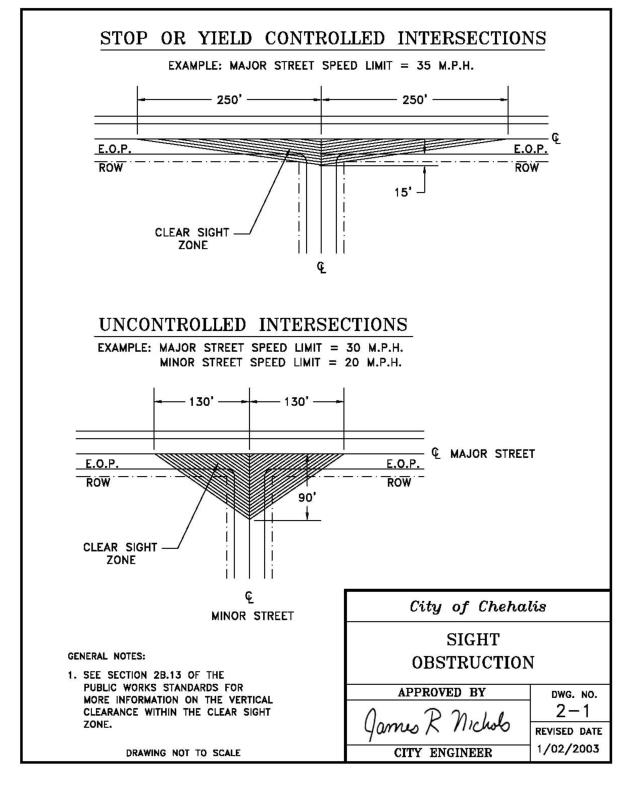
2-2 Pavement Design
2-3 Pavement Design Worksheet
2-4 Trench Pavement Restoration Detail
2-5 Pavement Restoration
2-6 Pavement Patch
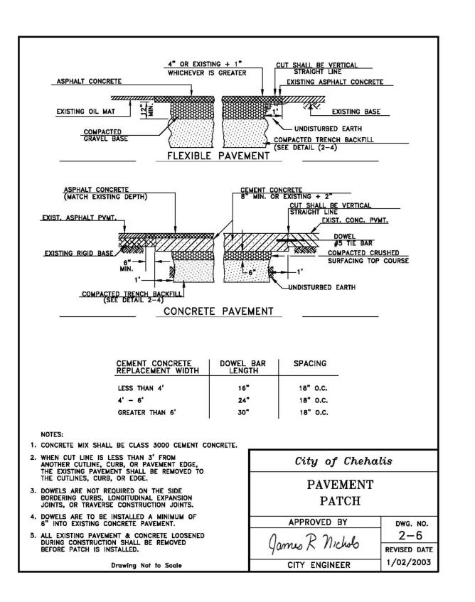
2-7 Cement Concrete Curb & Gutter
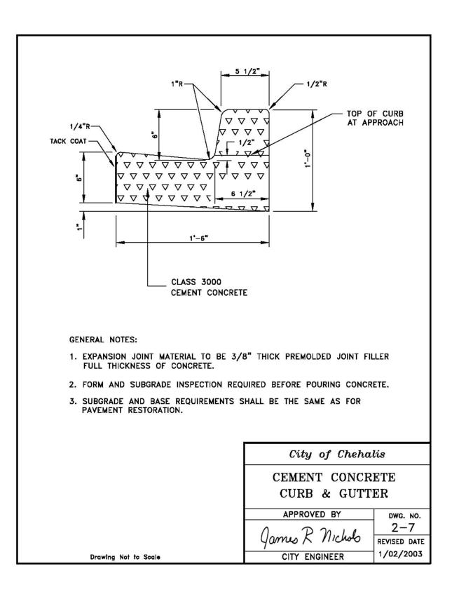
2-8 Cement Concrete Driveway
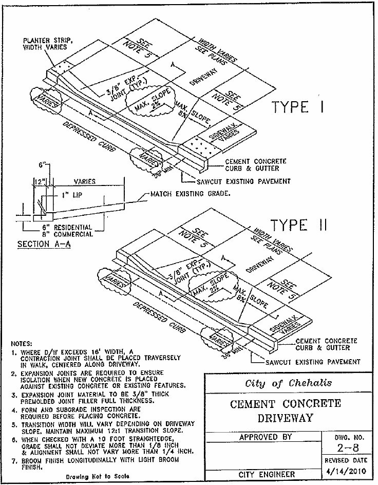
[Ord. 858B § 4, 2010.]
2-9 Sidewalk
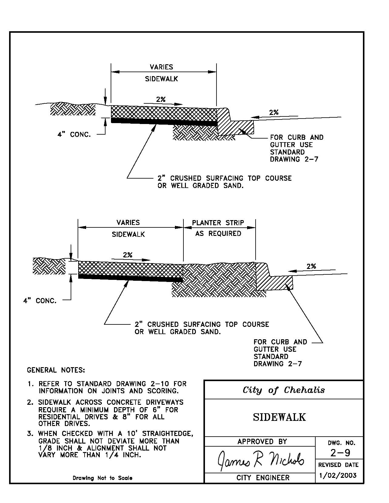
2-10 Sidewalk Spacing – Expansion Joints & Score Marks
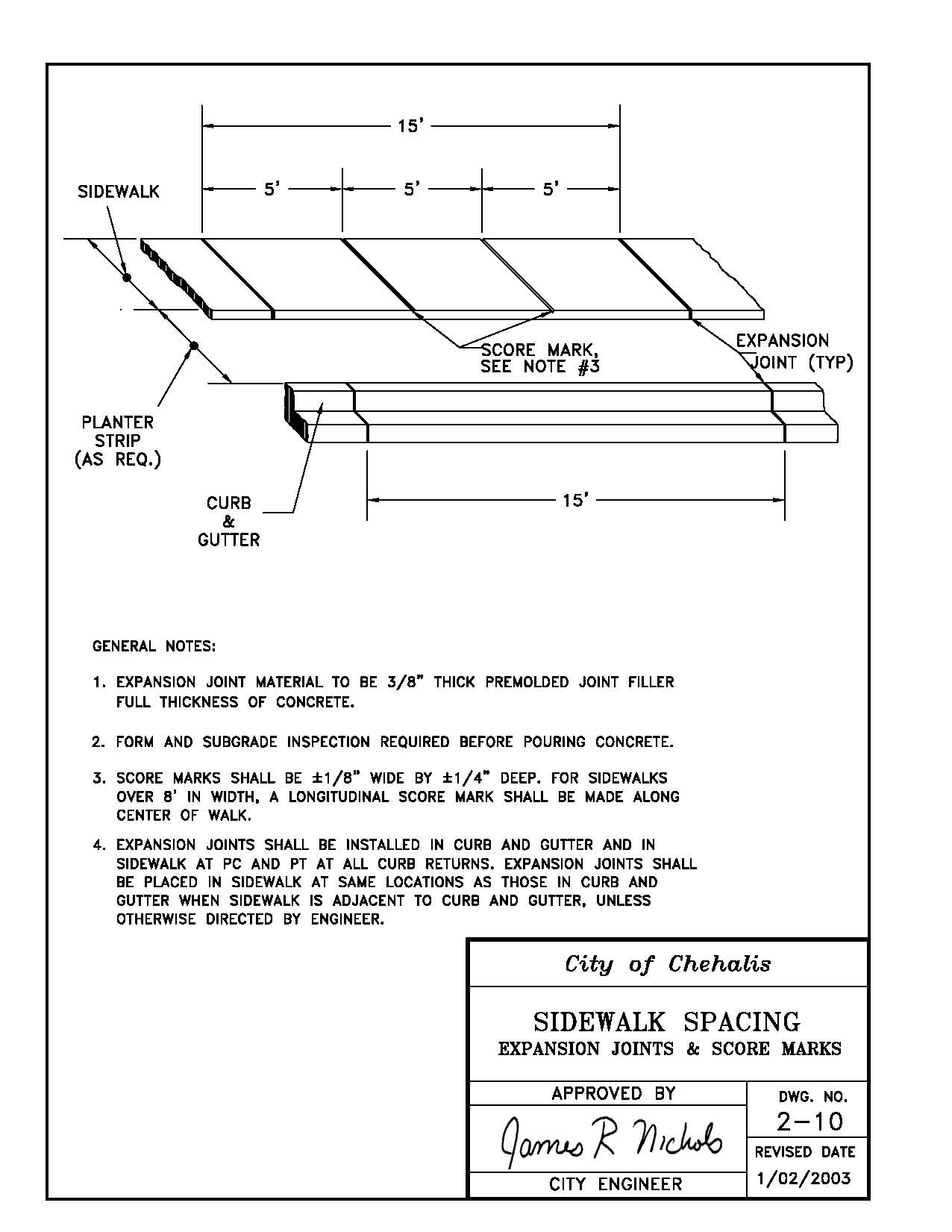
2-11 Curb Ramp Construction Details
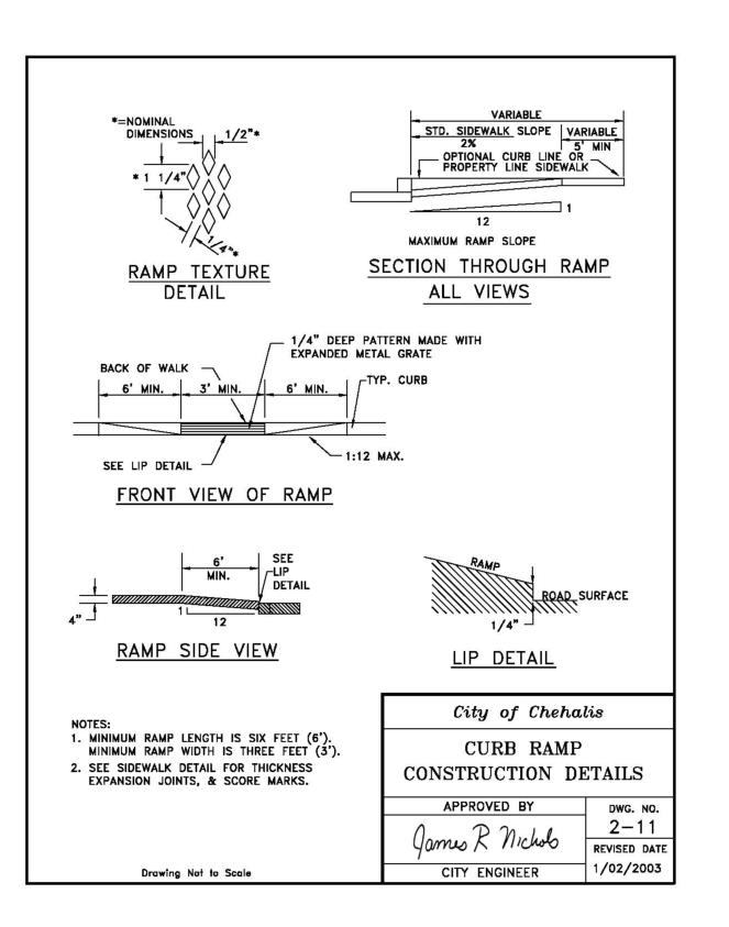
2-12 Types A & B Curb Ramps
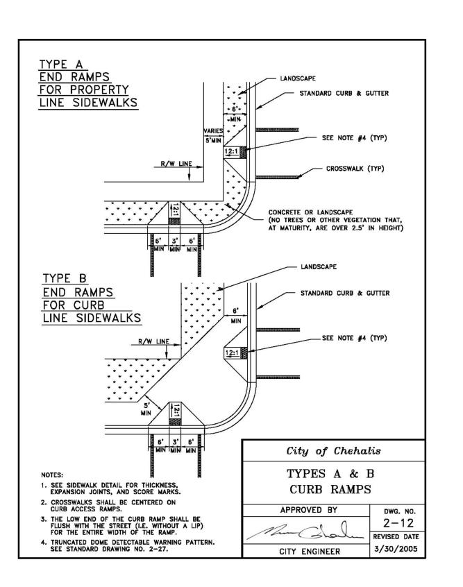
2-13 Types C & D Curb Ramps
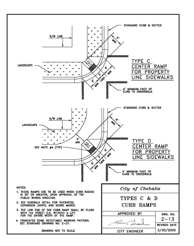
2-14 Types E & F Curb Ramps
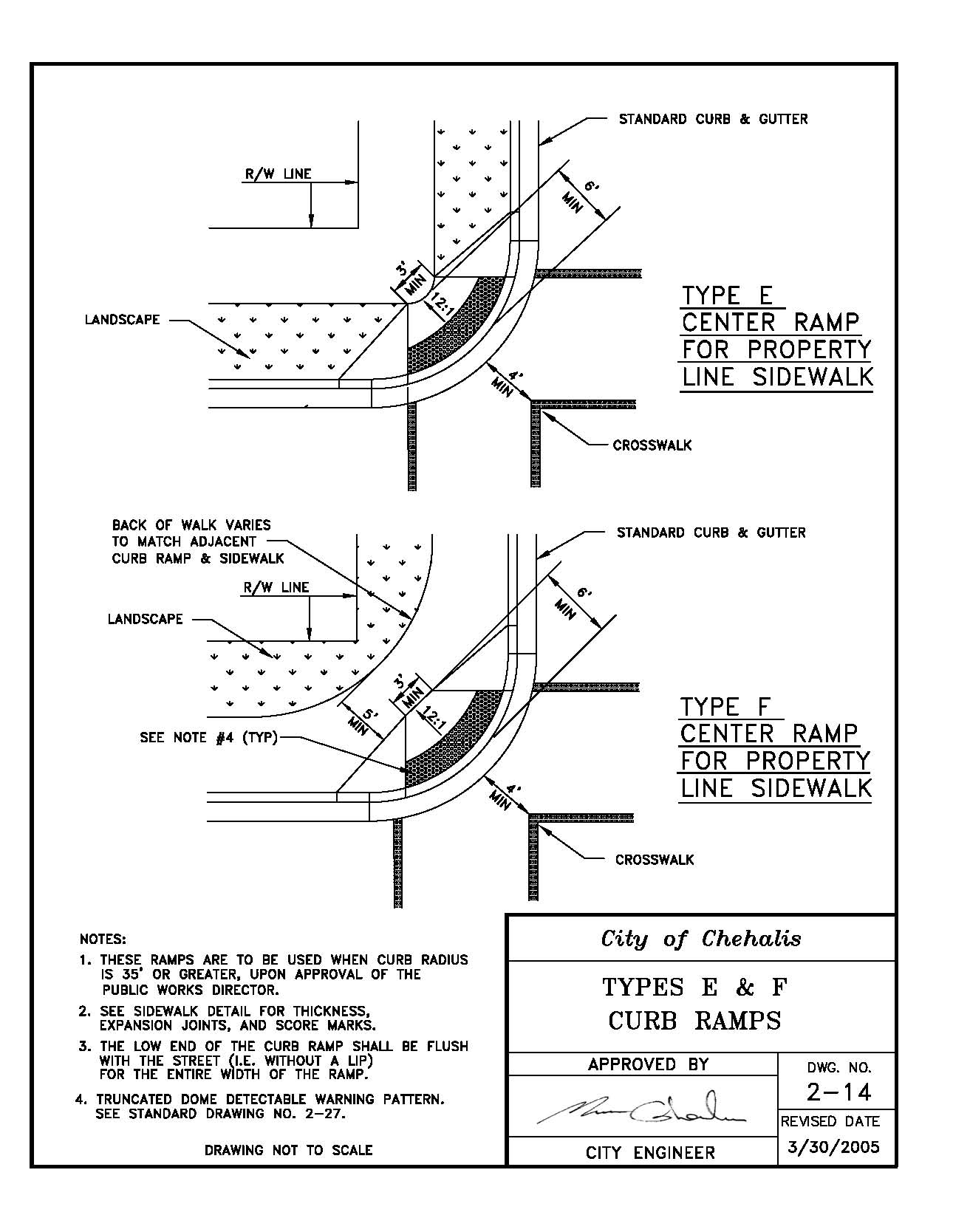
2-15 Mid-Block Curb Ramps
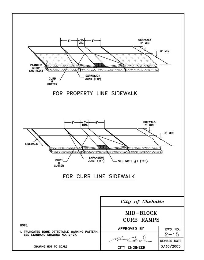
2-16 Luminaire Foundation
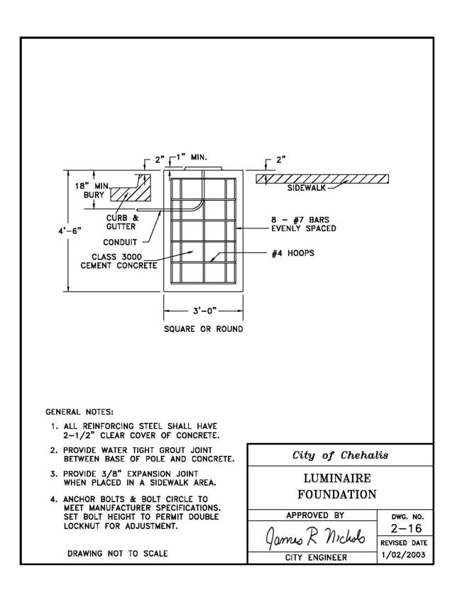
2-17 Service Disconnect for Street Lights & Traffic Signals
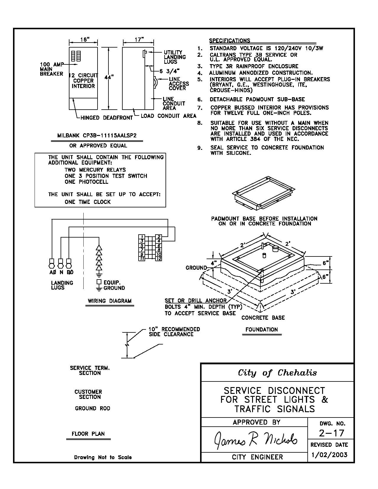
2-18 Mail Box Cluster
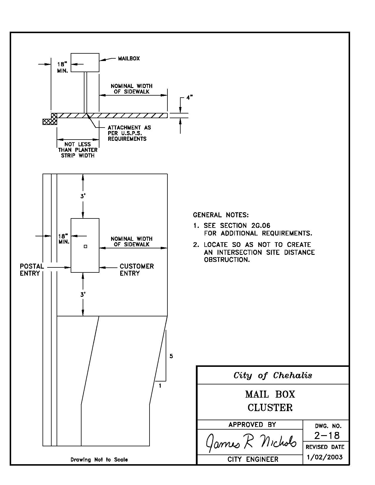
2-19 Cast in Place Monument
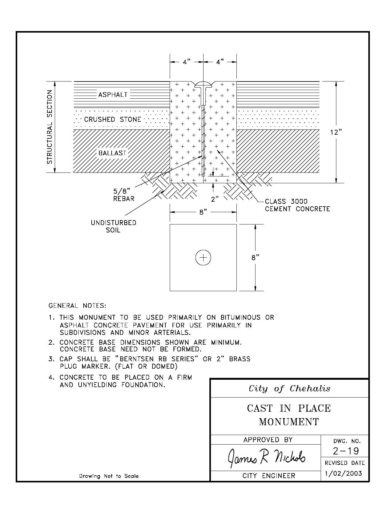
2-20 Monument Case and Cover with Riser
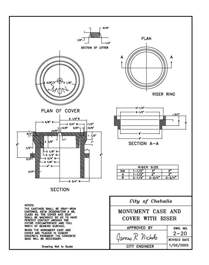
2-21 Monument Case Installation
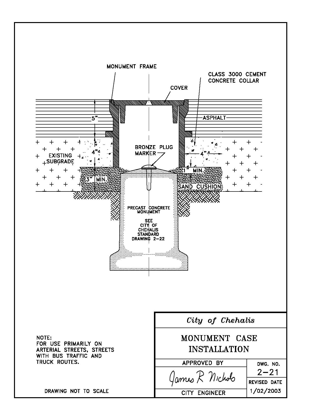
2-22 Precast Concrete Monument
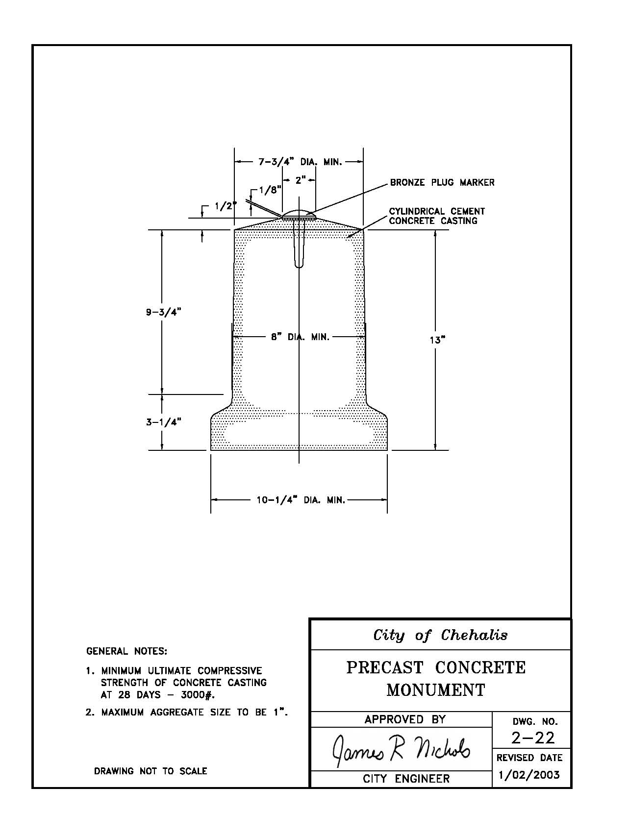
2-23 Retaining Wall
2-24 Striping Detail
2-25 Speed Berm Cross Section
2-26 Steel Sign Post Base Connection
2-27 Truncated Domes
2-28 Street Light, Alternative 1
[Ord. 858B § 5, 2010.]
3-1 Catch Basin with Silt Trap Tee
3-2 Stabilized Construction Entrance
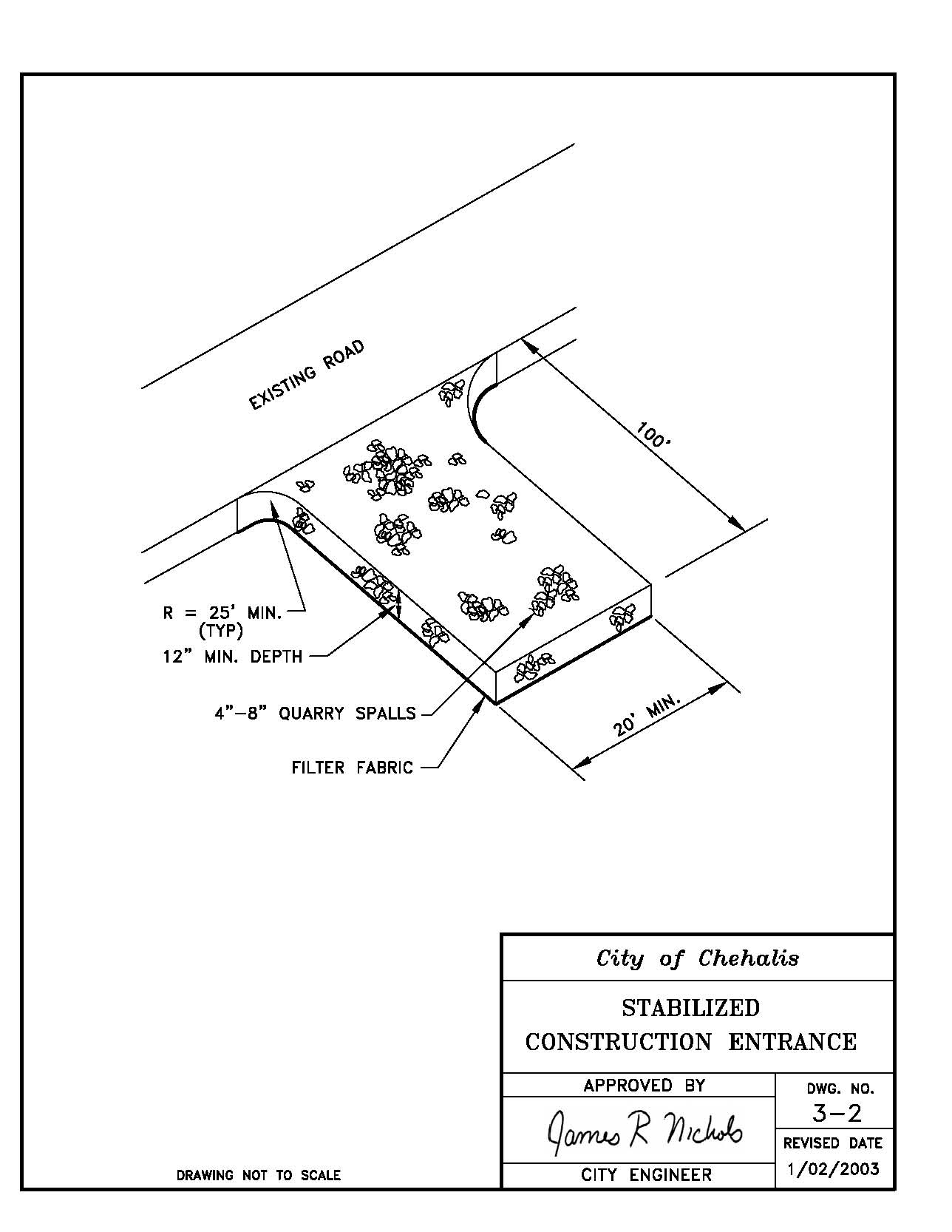
3-3 Driveway Culvert
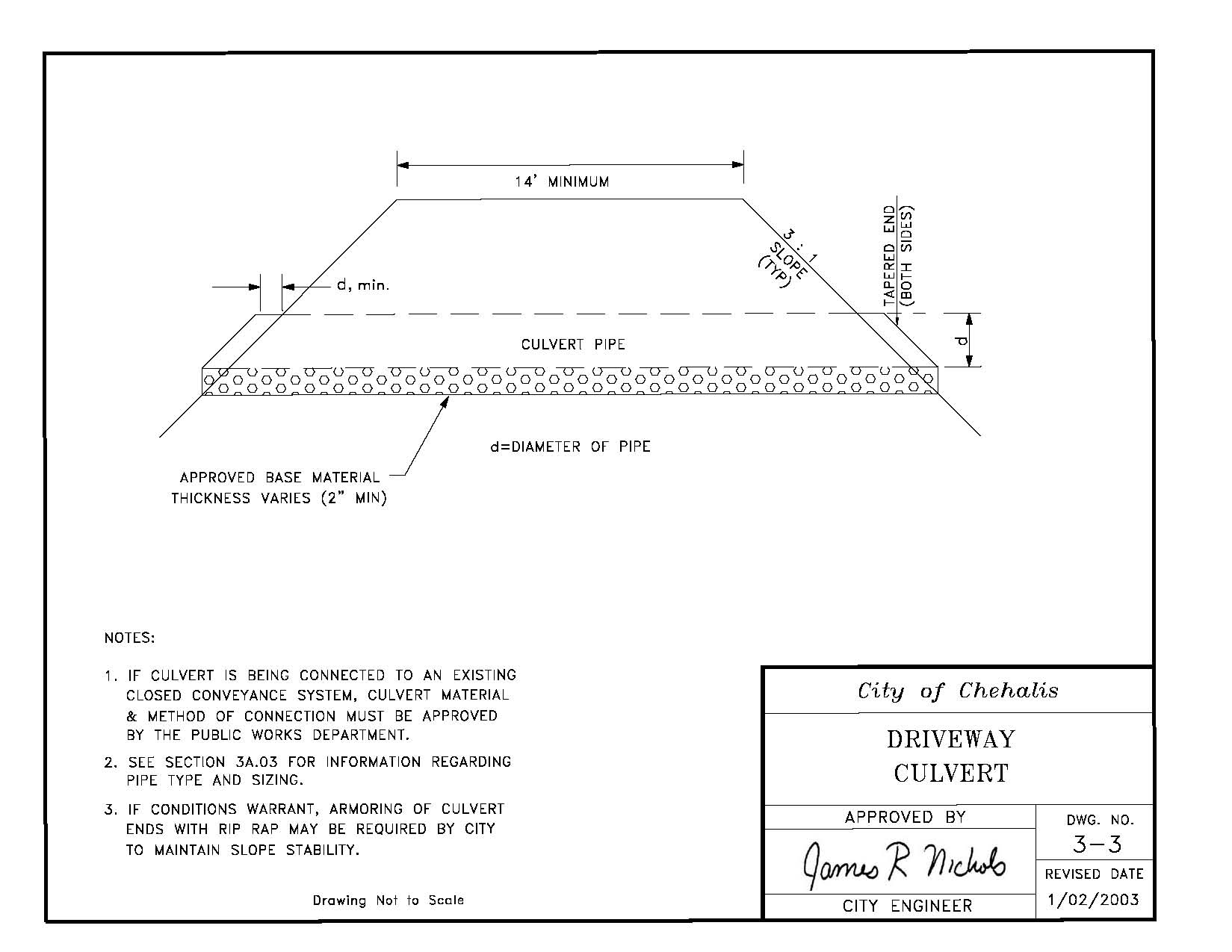
3-4 Temporary Silt Fence
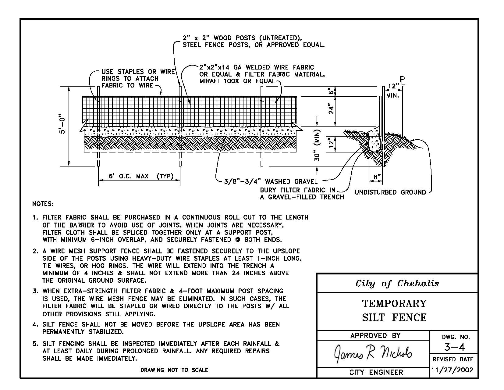
3-5 Filter Fabric Catch Basin Protection
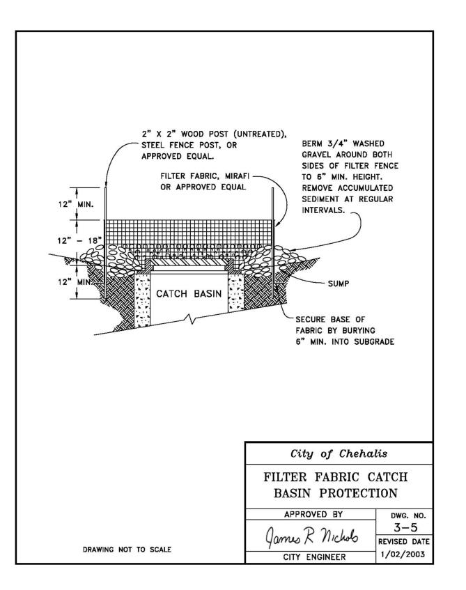
3-6 Temporary Strawbale Check Dam
3-7 Temporary “V” Ditch
3-8 Gravel Cone with Riser
3-9 Catch Basin Type 2
4-1 5/8" x 3/4" Single Water Service
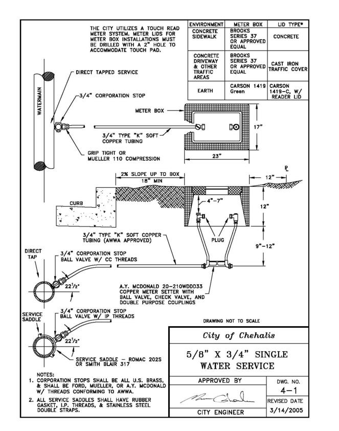
4-2 1" Dual Water Service
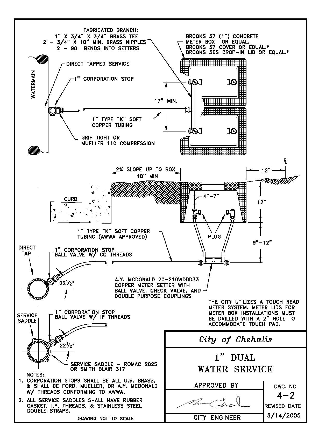
4-3 1-1/2" – 2" Water Service with Bypass
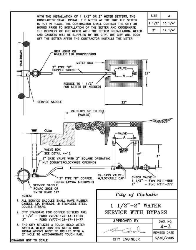
4-4 Compound Water Meter with Bypass for 3" – 8" Water Service
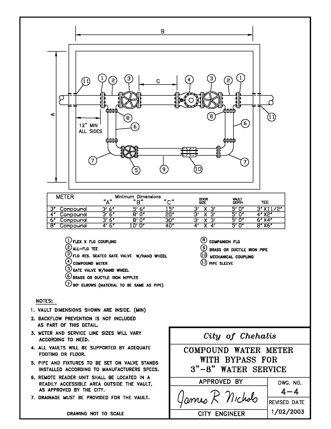
4-5 Large Meter Vault
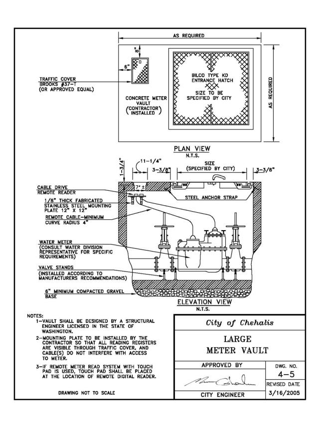
4-6 Fire Department Connection w/ DCDA for Single Service
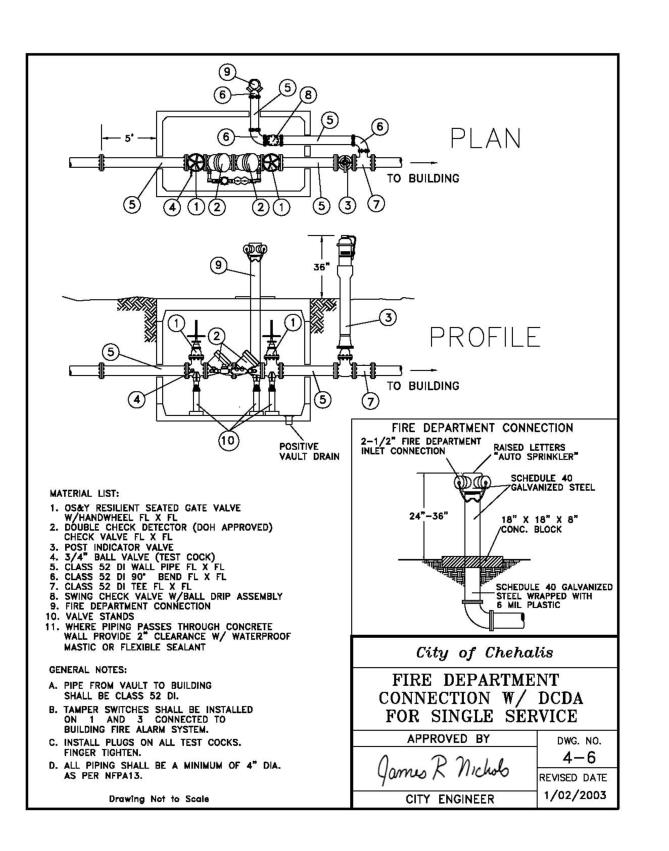
4-7 Fire Department Connection w/ DCDA for Dual Service
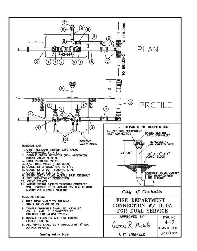
4-8 Fire Hydrant
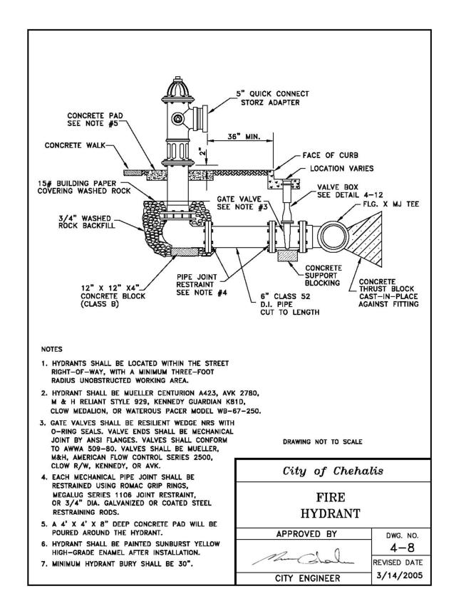
4-9 Air and Vacuum Relief Valve
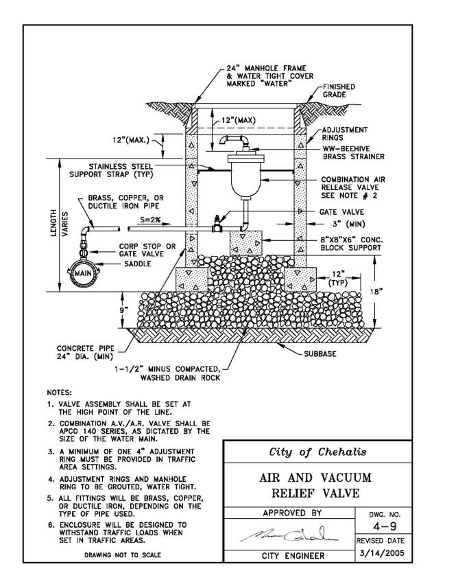
4-10 2" Blowoff Assembly
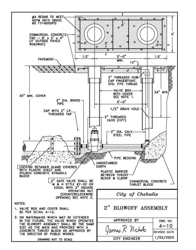
4-11 Connection to Existing Main
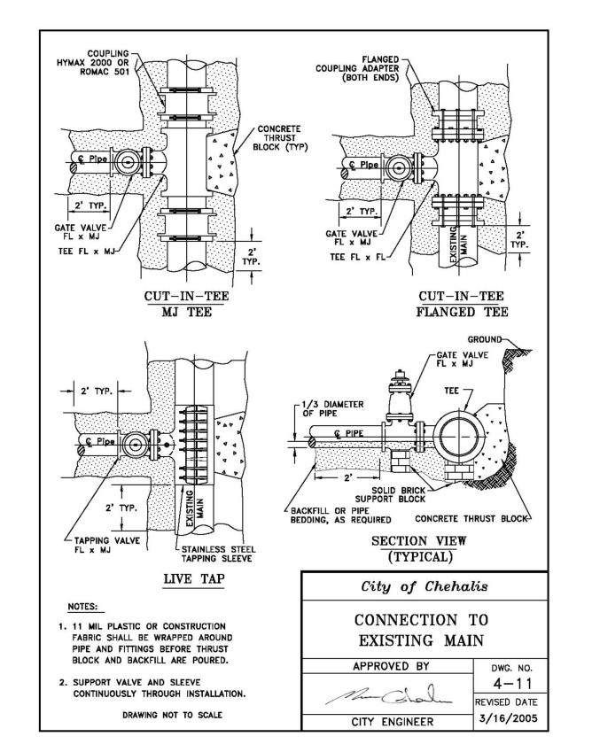
4-12 Valve Box
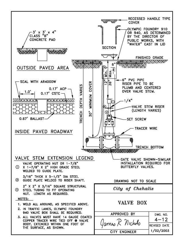
4-13 Standard Blocking Detail
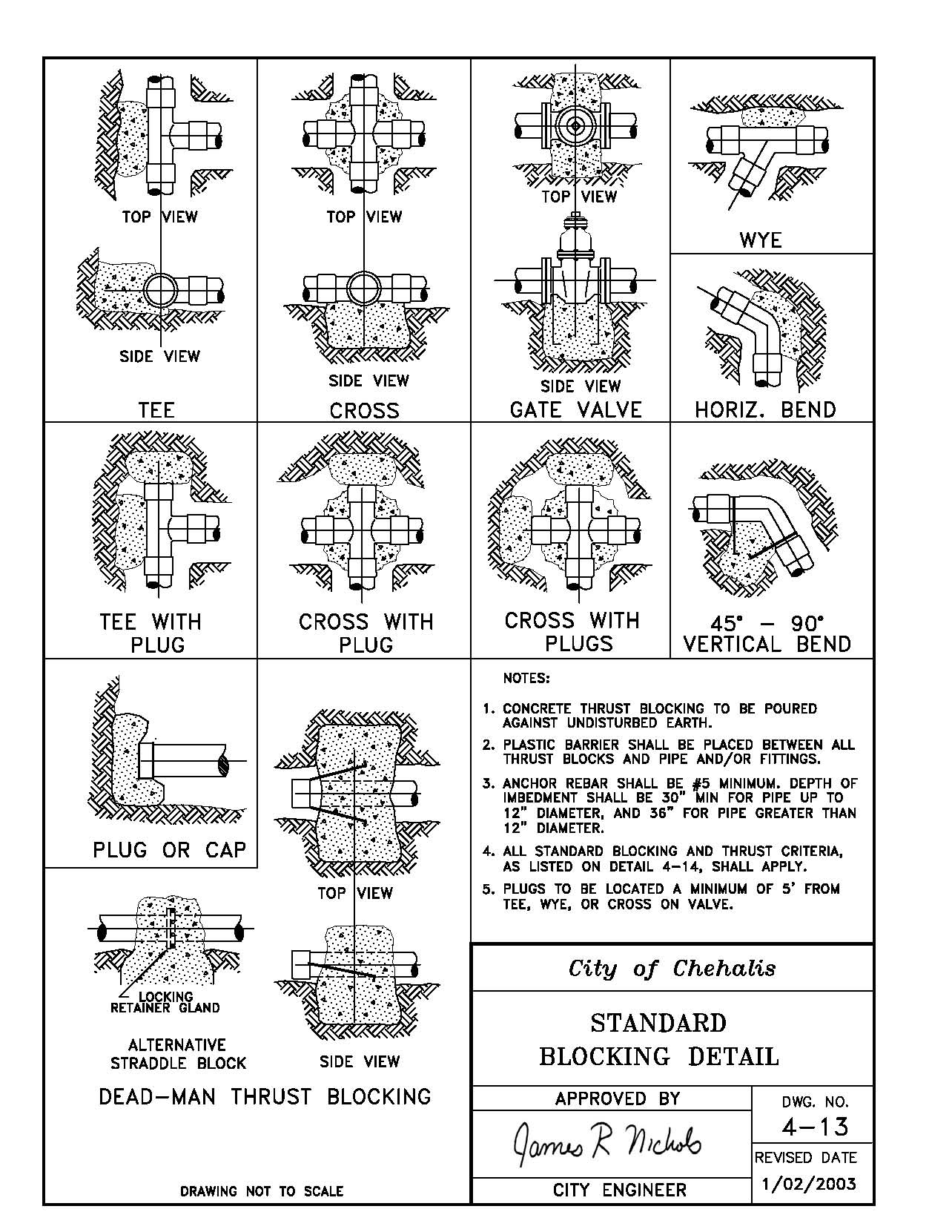
4-14 Thrust Loads
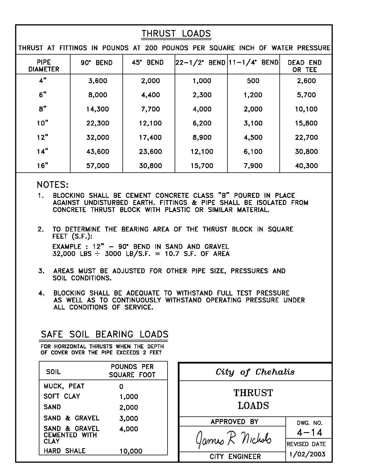
4-15 Standard Double Check Detector Assembly 3" or Larger
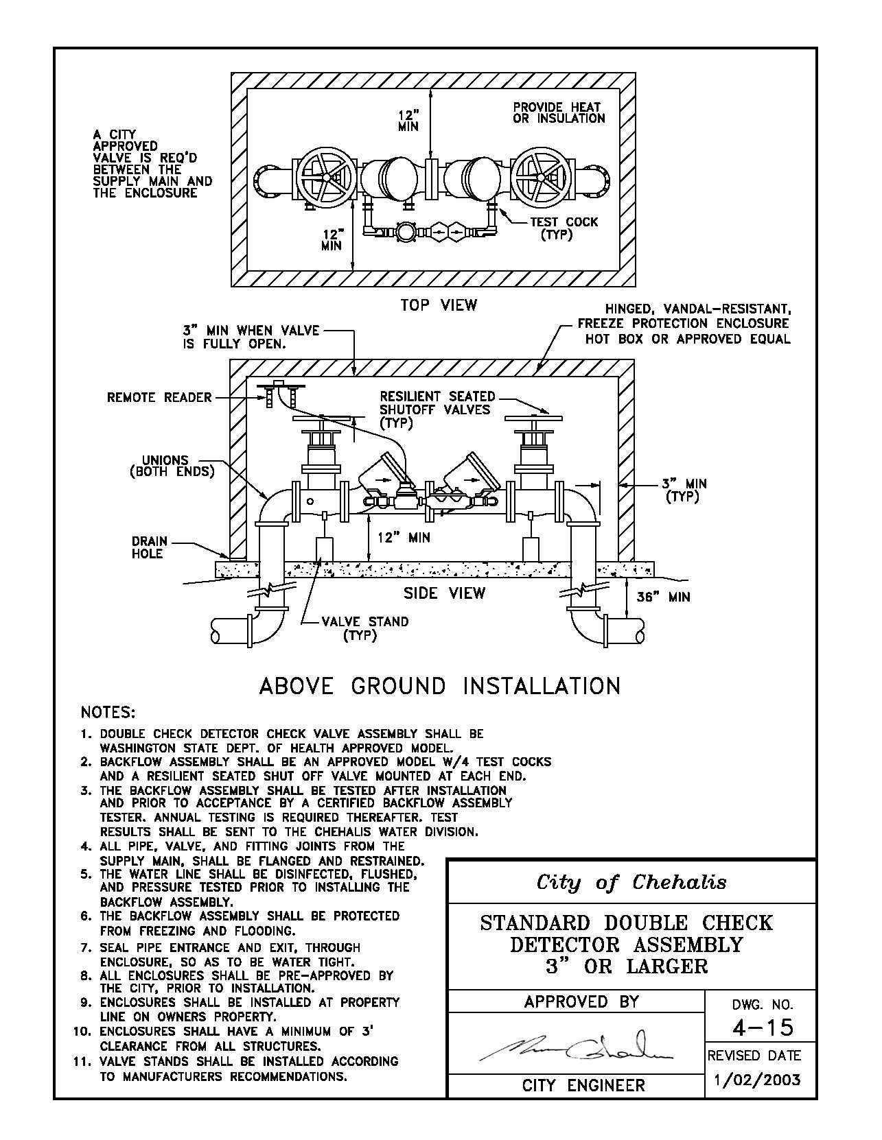
4-16 Standard Reduced Pressure Backflow Assembly 3" or Larger
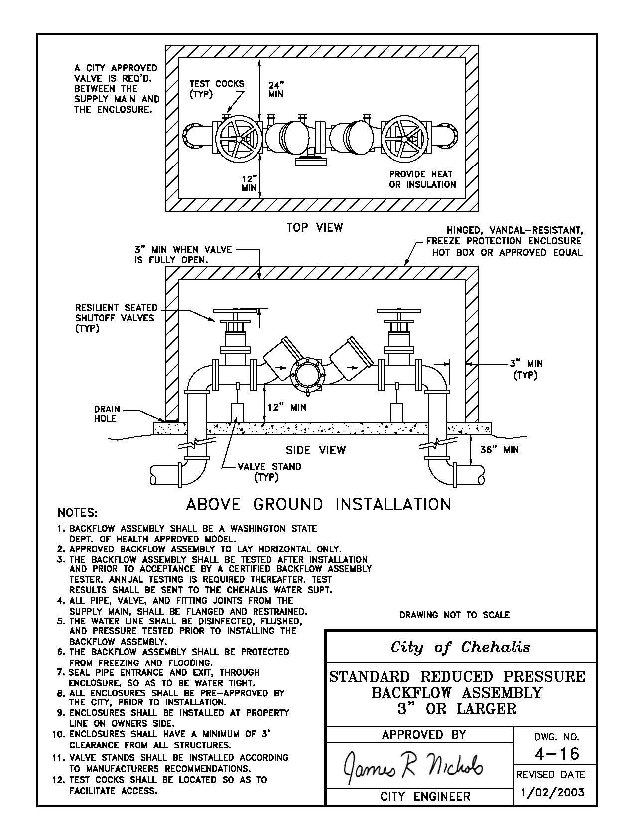
4-17 1/2" – 2" PVBA/SVBA Backflow Preventer
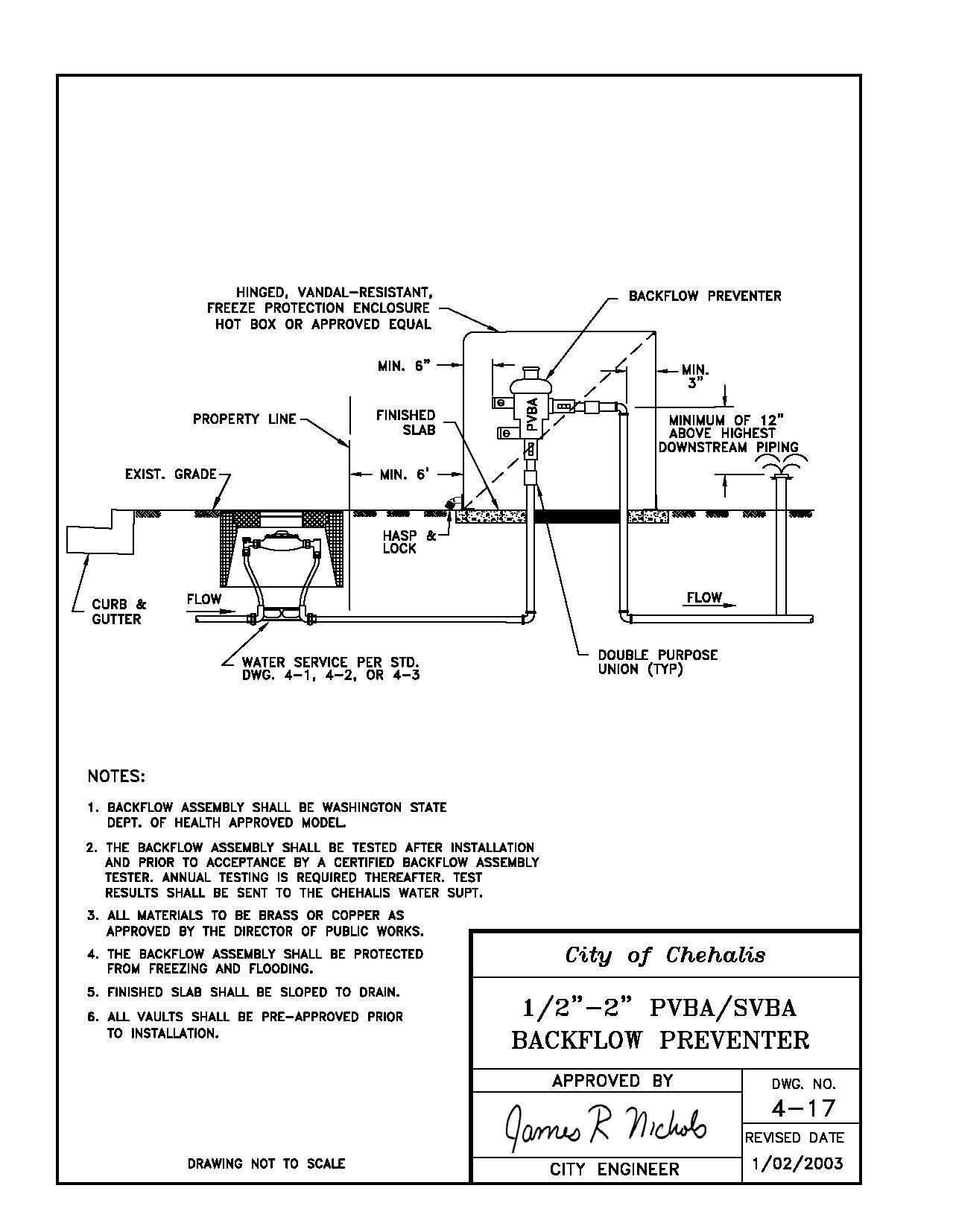
4-18 1/2" – 2" Double Check Backflow Preventer
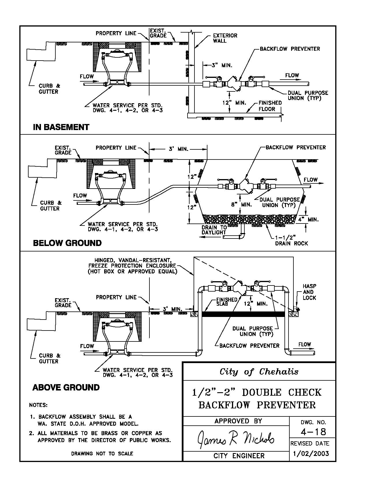
5-1 Typical Manhole
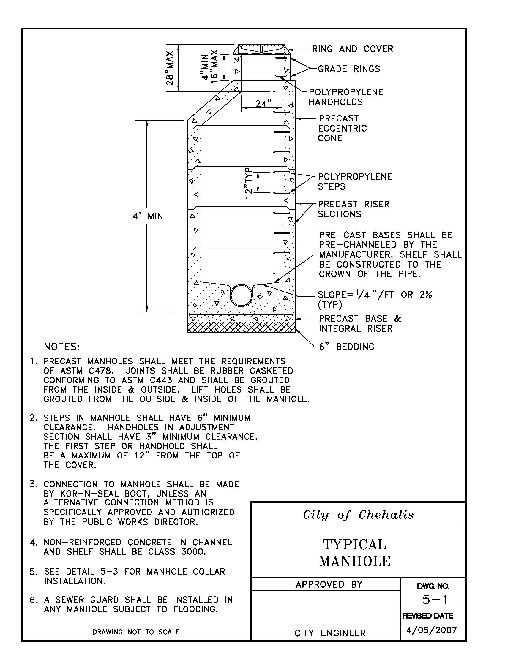
[Ord. 819B § 18, 2007.]
5-2 Shallow Manhole
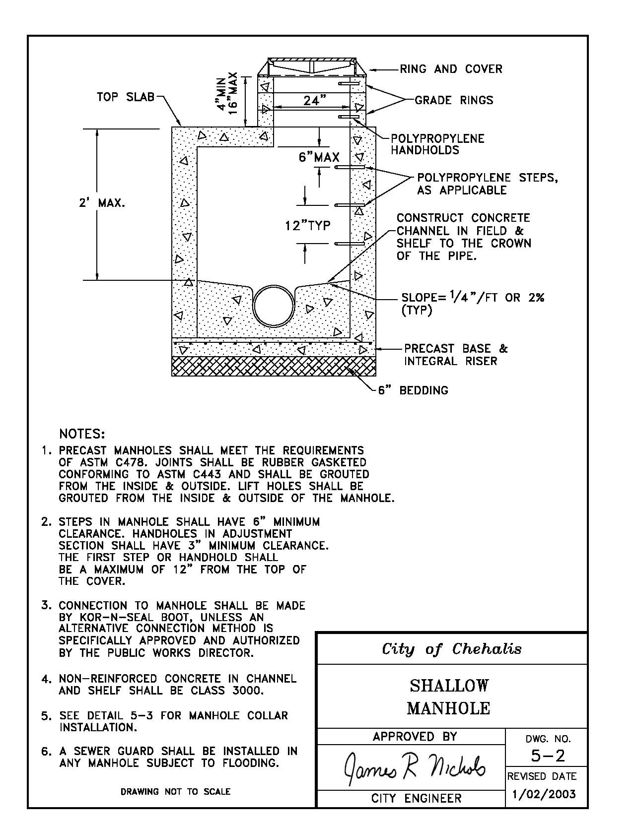
5-3 Manhole Collar
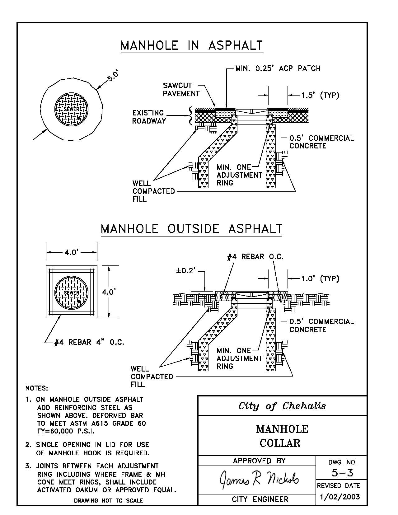
5-4 Drop Connection
5-5 Cleanout
5-6 1,000 Gallon S.T.E.P. System Septic Tank
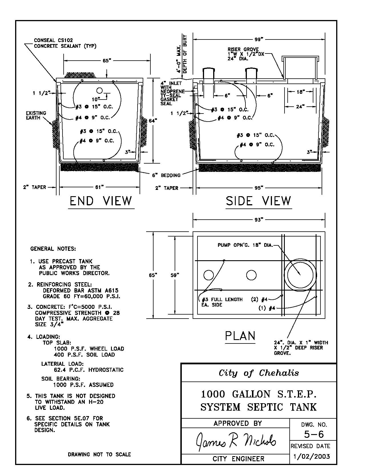
5-7 1,000 Gallon S.T.E.P. System Septic Tank
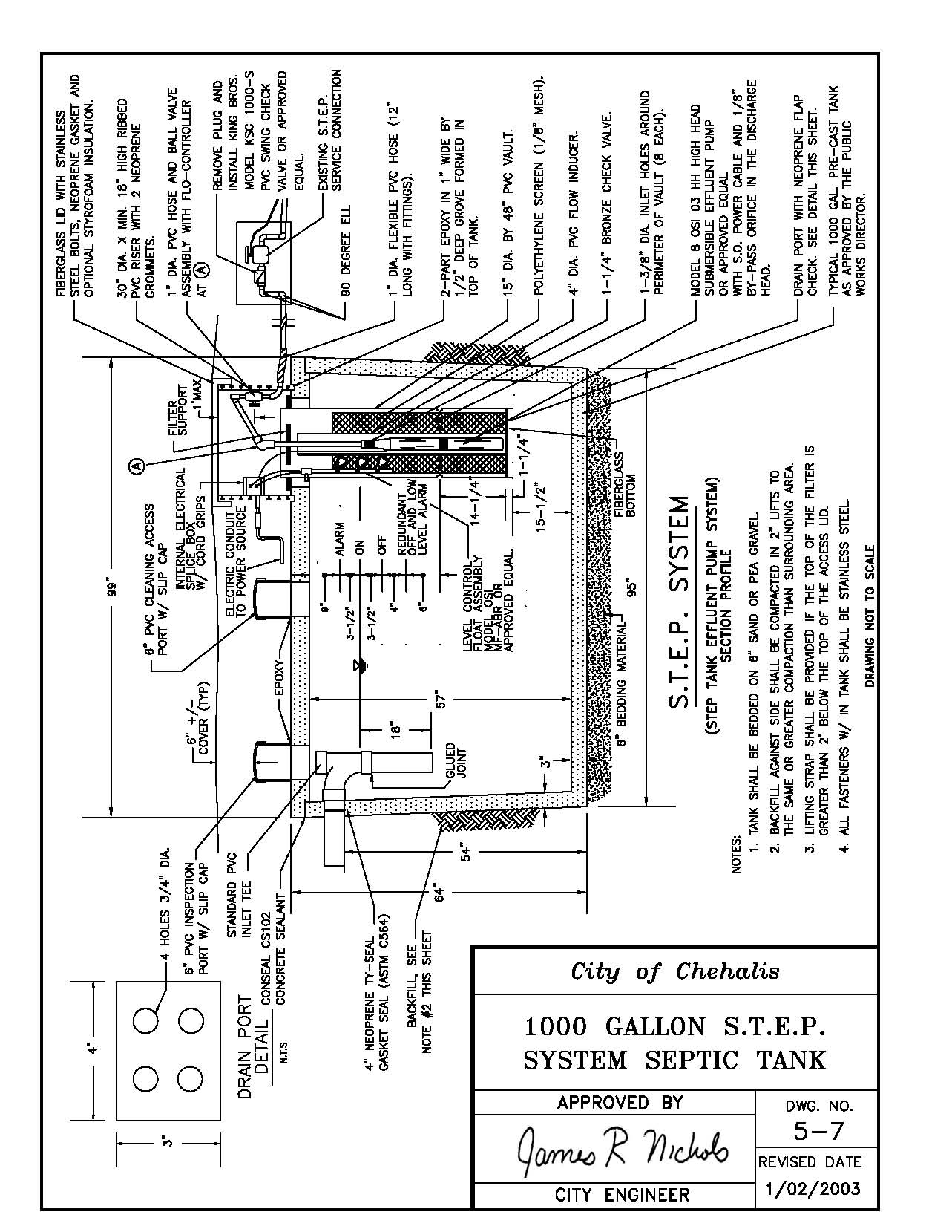
5-8 S.T.E.P. System Air Release Assembly
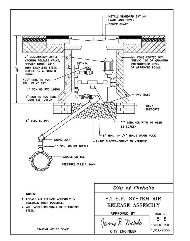
5-9 S.T.E.P. System Service Connection
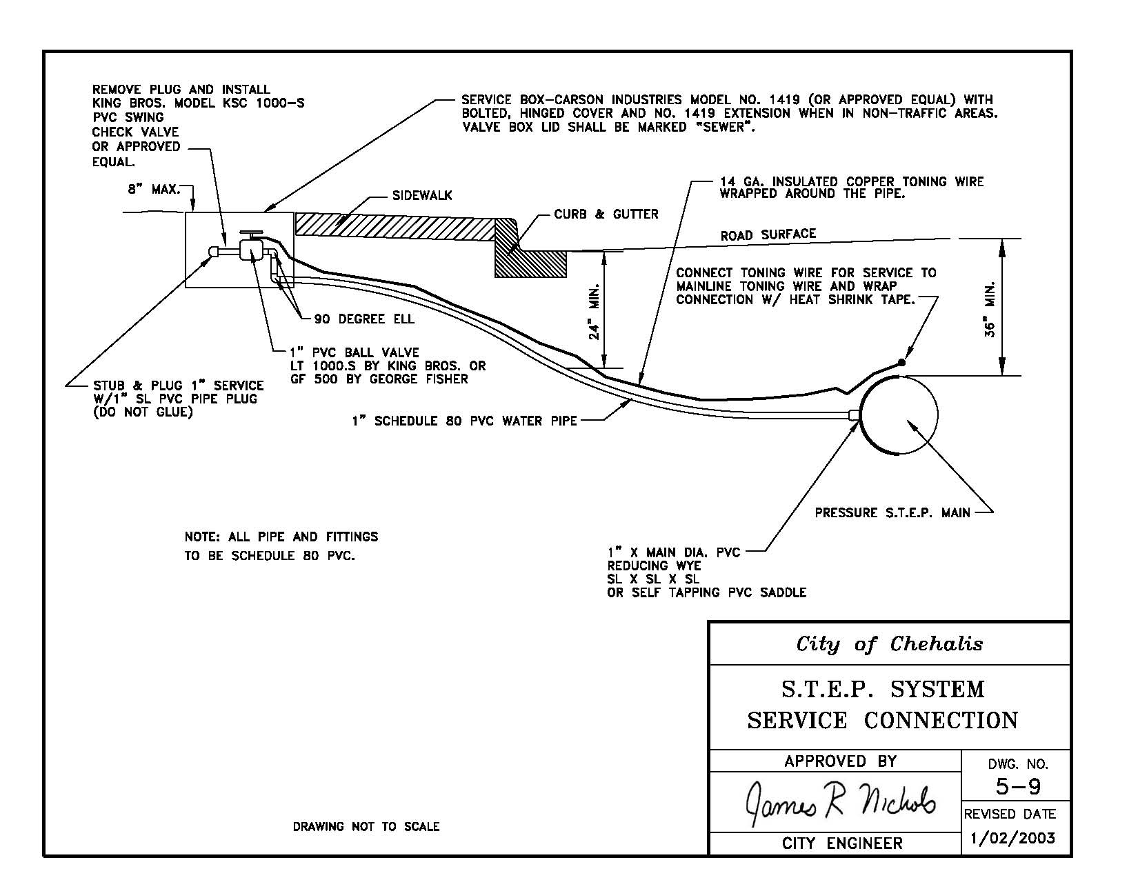
5-10 Sanitary Sewer Lateral Service Connection
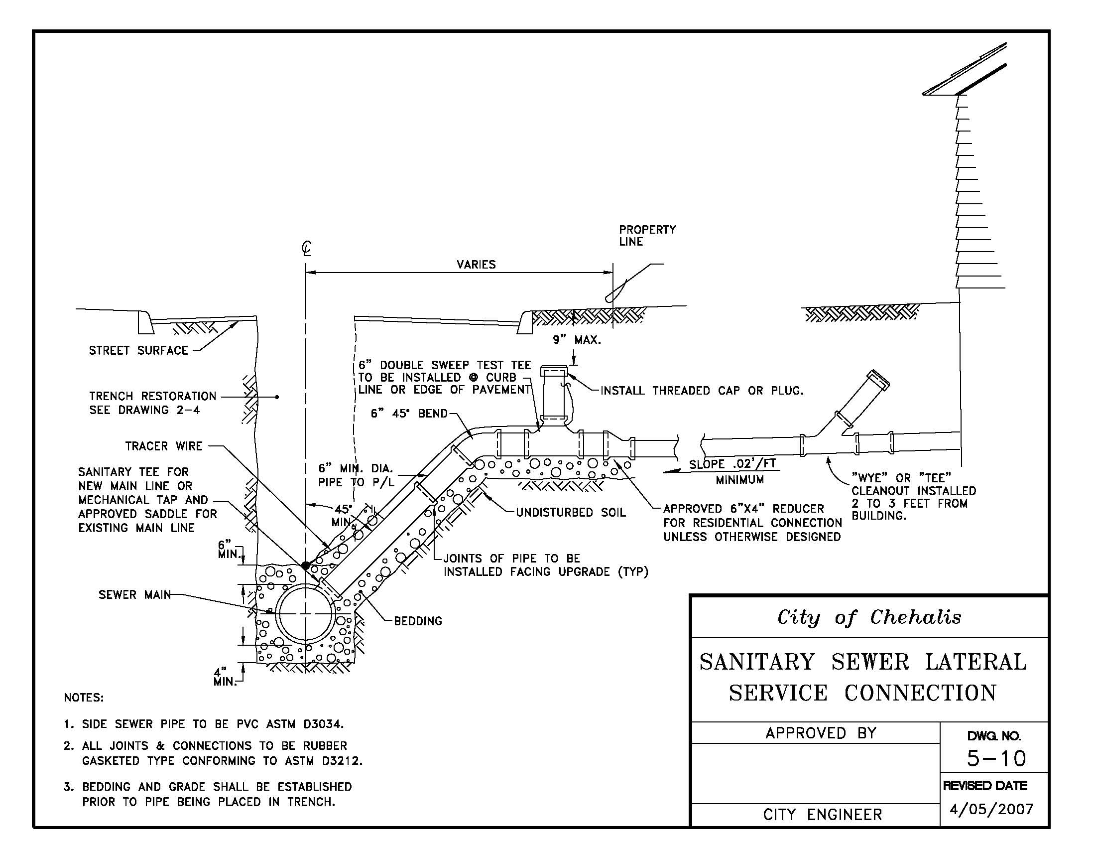
[Ord. 819B § 18, 2007.]
5-11 Side Sewer Cleanout
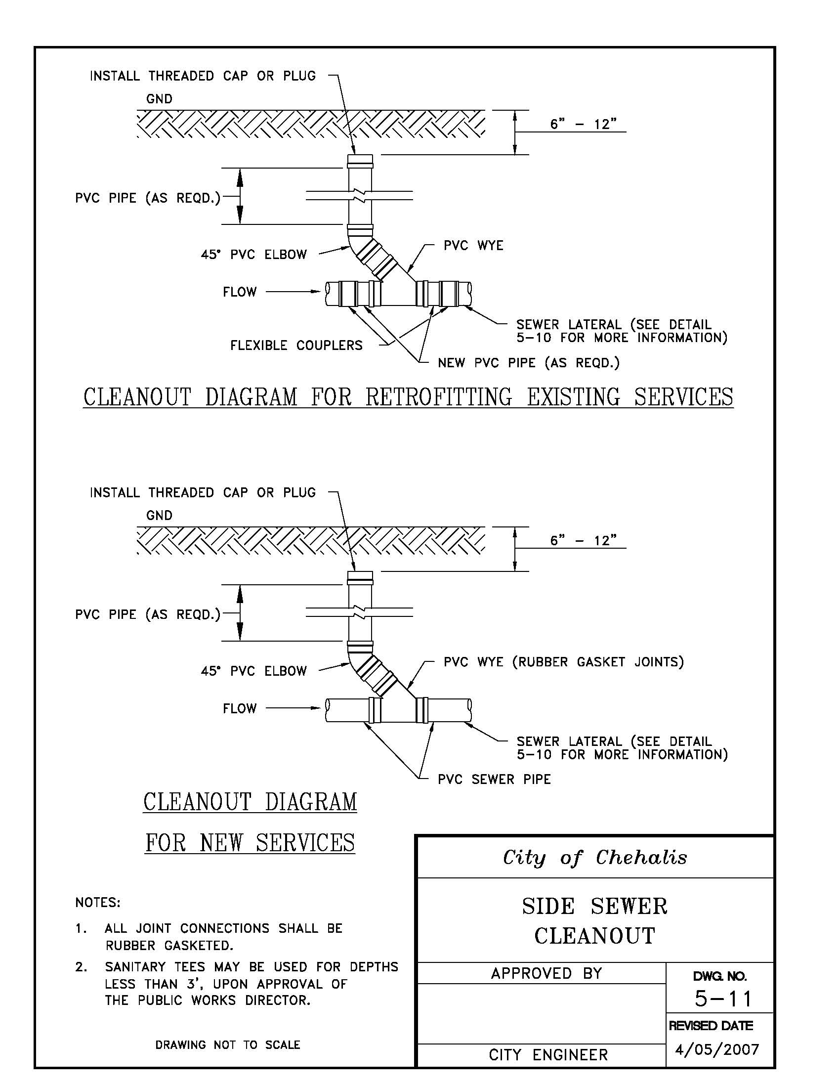
[Ord. 819B § 18, 2007.]
5-12 Sanitary Sewer Saddle Tap
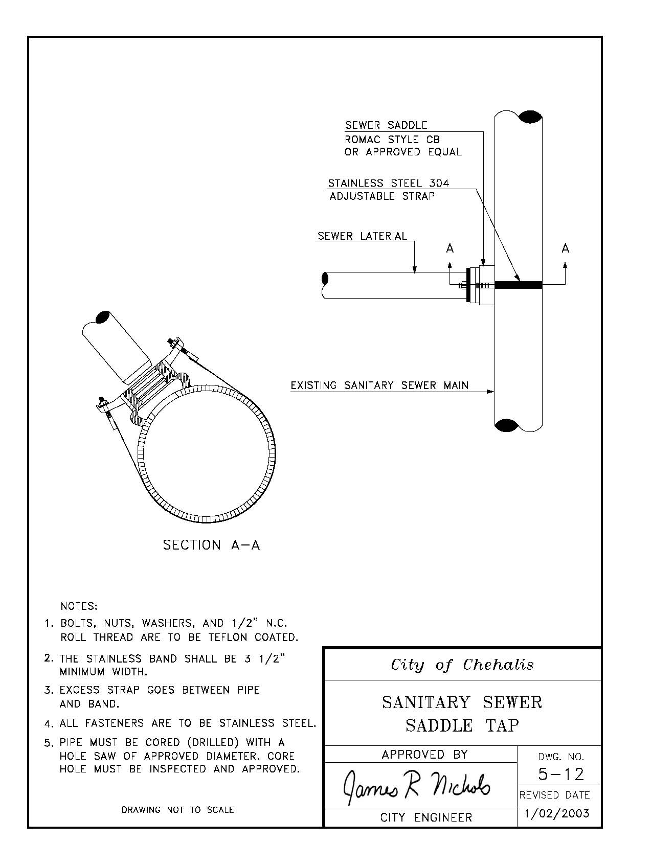
5-13 Side Sewer Plug
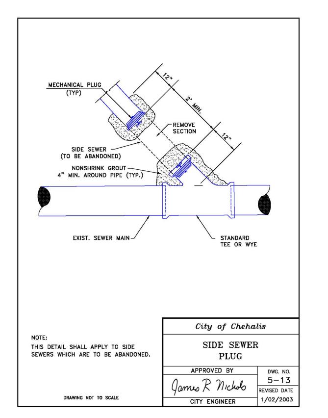
5-14 Sewer Main Connection
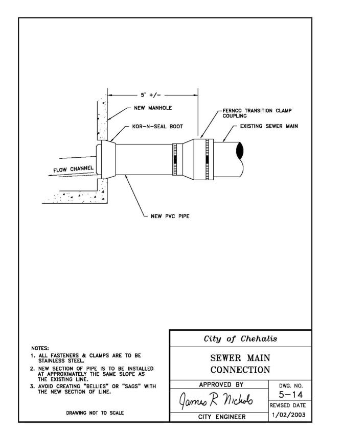
5-15 Pig Port
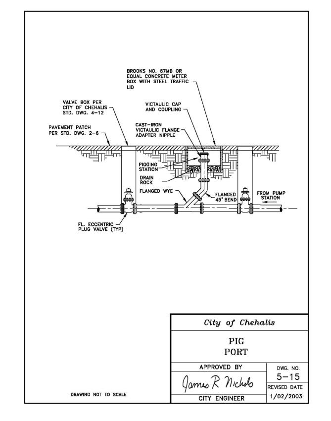
Code reviser’s note: For statutory provisions authorizing cities to adopt any printed code or compilation by reference, see RCW 35.21.180; for similar provisions relating to code cities, see RCW 35A.12.140.